Table of Contents
Advertisement
Advertisement
Table of Contents

Related Manuals for APRILIA CLASSIC 125 - 1997


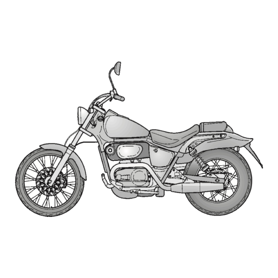
Summary of Contents for APRILIA CLASSIC 125 - 1997
- Page 1 Classic 125 aprilia part# 8102785...
- Page 2 This manual is to be considered an integral part of the vehicle, which must be delivered complete with it also in case of resale. aprilia s.p.a. reserves the right to modify its models at any time, without prejudice to the main characteristics here described.
- Page 3 Authorized Outlets and Official Dealers, who can ensure you reliable and prompt servicing. catalytic version Thank you for choosing aprilia. We wish you a nice ride. Italy version United Kingdom version Switzerland version IMPORTANT: £...
-
Page 4: Table Of Contents
TABLE OF CONTENTS SAFE DRIVE ..................... 5 CHAIN .......................34 BASIC SAFETY RULES ................6 CHECKING THE TRANSMISSION OIL LEVEL........36 CLOTHING ....................9 CHANGING THE TRANSMISSION OIL ...........37 ACCESSORIES..................10 FRONT WHEEL ..................38 LOAD ......................10 REAR WHEEL ..................39 REMOVING THE FUEL TANK..............40 ARRANGEMENT OF THE MAIN ELEMENTS .......... -
Page 5: Safe Drive
safe drive... -
Page 6: Basic Safety Rules
BASIC SAFETY RULES The use of medicins, alcohol and drugs or Most road accidents are caused by the psychotropic substances notably increases driver’s lack of experience. To drive the vehicle it is necessary to be in the risk of accidents. NEVER lend the vehicle to beginners and, possession of all the requirements pre- Be sure that you are in good psychophysi-... - Page 7 Rigorously observe all road signs and na- Avoid obstacles that could damage the ve- Always drive with both hands on the han- tional and local road regulations. hicle or make you lose control. dlebars and both feet on the footrests (or Avoid abrupt movements that can be dan- on the rider’s footboards), in the correct Avoid riding in the slipstream created by...
- Page 8 If necessary, have the vehicle inspected by an aprilia Official Dealer, who should care- fully check the frame, handlebars, suspen- sions, safety parts and all the devices that you cannot check by yourself.
-
Page 9: Clothing
ONLY ORIGINALS Never change the position, inclination or Any modification of the vehicle and/or the CLOTHING colour of: number plate, direction indica- removal of original components can com- Before starting, always wear a correctly tors, lights and horns. promise vehicle performance levels and fastened crash helmet. -
Page 10: Accessories
(aprilia genuine accessories). - Page 11 Avoid hanging bulky, heavy and/or danger- Do not carry any bag if it is not tightly se- Do not exceed the maximum load allowed ous objects on the handlebars, mudguards cured to the vehicle. for each side-bag. and forks, because the vehicle might re- Do not carry bags which protrude too much When the vehicle is overloaded, its stability spond more slowly in turns and its ma-...
-
Page 12: Arrangement Of The Main Elements
ARRANGEMENT OF THE MAIN ELEMENTS Fig. 1 KEY Fig. 1 1) Mixer oil tank plug 6) Fuses 2) Air cleaner 7) Battery 3) Saddle lock 8) Side stand 4) Rear suspension spring preload adjusting ring 9) Footrest 5) Passenger's footrest 10) Shifting lever use and maintenance Classic 125... - Page 13 Fig. 2 KEY Fig. 2 1) Fuel cock 7) Footrest 2) Fillercap 8) Took kit/glove compartment 3) Front brake fluid tank 9) Passenger's footrest 4) Ignition switch/steering lock 10) Rear suspension spring preload adjust- 5) Mixer oil tank ing ring 6) Rear brake control lever use and maintenance Classic 125...
-
Page 14: Arrangement Of The Instruments
ARRANGEMENT OF THE INSTRUMENTS INSTRUMENTS AND INDICATORS Fig. 3 Fig. 4 KEY Fig. 3 KEY Fig. 4 1) Left rear-view mirror 1) Speedometer 2) Clutch lever 2) Total kilometres odometer 3) High beam signalling push button ( 3) Coolant overheating warning light ( 4) Cold start lever ( 4) Red mixer oil reserve warning light ( 5) Ignition switch/steering lock (... -
Page 15: Instruments And Indicators
INSTRUMENTS AND INDICATORS Description Function Speedometer It indicates the driving speed. Total kilometres odometer It indicates the total number of kilometres covered. It comes on when the coolant reaches or exceeds the limit temperature. In this case, stop the engine and check the coolant level, see p. 24 (COOLANT). Coolant overheating warning light If the maximum allowed temperature is exceeded (the warning light comes on),... -
Page 16: Main Independent Controls
MAIN INDEPENDENT CONTROLS CONTROLS ON THE LEFT SIDE OF THE HANDLEBAR (Fig. 5) The electrical parts work only when the ignition switch is in position " ". 1) DIMMER SWITCH ( When the light switch (right side of the handlebar) is in posi- tion "... -
Page 17: Controls On The Right Side Of The Handlebar
CONTROLS ON THE RIGHT SIDE OF THE HANDLEBAR (Fig. 6) The electrical parts work only when the ignition switch is in position " ". 1) HEADLIGHT SWITCH ( - • ) When the light switch is in position " • ", the lights are off; when the switch is in position "... -
Page 18: Ignition Switch
STEERING LOCK (Fig. 7) Never turn the key to position " " in running conditions, in or- der to avoid losing control of the vehicle. OPERATION To lock the steering: Turn the handlebar completely leftwards. Turn the key to position " "... -
Page 19: Crash Helmet/Glove Compartment
MAIN COMPONENTS FUEL The fuel used for internal com- bustion engines is extremely in- flammable and in particular con- ditions it can become explosive. It is important to carry out the refuelling and the maintenance operations in a well-ventilated area, with the engine off. Do not smoke while refuelling or near fuel vapours, in any case avoid any con- tact with naked flames, sparks and any... -
Page 20: Transmission Oil
Wash your hands carefully after station where you usually buy it. usual checking operations, contact using the oil. Do not dispose of your aprilia Official Dealer. the oil in the environment. Make sure that the brake disc is neither KEEP AWAY FROM CHILDREN. -
Page 21: Front Brake
(1) is pa- aprilia Official Dealer, since it may be this reason they must always be rallel to the "MIN" mark on the glass. -
Page 22: Rear Brake
The idle stroke at the end of the brale le- out the normal checking operations, do ver pedal must be about 5 ÷ 10 mm. not hesitate to contact an aprilia Offi- cial Dealer. use and maintenance Classic 125... -
Page 23: Adjusting The Clutch
16): clutch does not function proper- Screw the adjusting screw (2 - Fig. 18) ly, contact an aprilia Official Dealer. Loosen the lock nut (2 - Fig. 16). with a screwdriver until taking up the Screw or unscrew the control lever ad- slack completely. -
Page 24: Adjusting The Shifting Lever
COOLANT To change the coolant, or in case of leaks in the circuit, con- tact an aprilia Official Dealer. Do not use the vehilce if the coolant is below the minimum prescribed level. Remember: 1 miles = 1.6 km 1 km = 0.625 miles Check the coolant level every 2000 km and Fig. -
Page 25: Tyres
Official Dealer or by a slip on the rim or it may become loose, qualified tyre repairer. -
Page 26: Catalytic Silencer
The catalytic Classic 125 is fitted with a si- What has been stated above assumes par- lencer with metal catalytic converter of the ticular importance for the cold starting of "platinum-rhodium bivalent" type. the engine: in this case, in order to reach a rpm regime sufficient to enable the "prim- This device provides for the oxidation of ing"... -
Page 27: Instructions For Use
Mixer oil/transmission Check and/or top up, if necessary. 20-36 Do not hesitate to consult your aprilia Official Dealer in case Check the tyre surface, the inflation pressure, wear and tear Wheel/tyres there is something you do not and any damage. -
Page 28: Starting
Fig. 21 Fig. 22 Fig. 23 STARTING Put the shifting lever into neutral (green Warm the engine up until it turns normal- warning light “ “ on) (1 - Fig. 22). ly with the cold start lever " " completely Exhaust gases contain carbon forwards. -
Page 29: Departure And Drive
To start the engine, proceed as follows: Make sure that the engine is warm. With released throttle grip and the en- gine idling, pull the clutch lever and en- gage the first gear by pressing the shift- ing pedal (Fig. 25). Slowly release the clutch lever and at the same time increase the engine rotation speed, by turning the throttle grip gradu-... - Page 30 Before beginning to turn, slow down or RUNNING-IN Between the first 1000 and 2000 km brake driving at moderate and constant drive more briskly, change speed and The running-in of the engine is important to speed or accelerating slightly; avoid use the maximum acceleration only for a ensure its correct functioning.
-
Page 31: Stopping And Parking
SUGGESTIONS TO PREVENT THEFT NEVER leave the ignition key inserted and always use the steering lock. Park the vehicle in a safe place, possibly in a garage or a protected place. When possible, use an additional anti-theft device. Make sure that all documents are in order and the road tax has been paid. -
Page 32: Maintenance
If you need as- Nut, bolt, screw tightening sistance or technical advice, consult your Suspensions and attitude aprilia Official Dealer, who can ensure you Brake fluid bleeding prompt and accurate servicing. Spoke tension After any maintenance operation, carry out... -
Page 33: Identification Data
Fig. 28 Fig. 29 ENGINE NUMBER (Fig. 28) FRAME NUMBER (Fig. 29) IDENTIFICATION DATA The engine number is stamped on the up- The frame number is stamped on the right It is a good rule to write down the frame and engine numbers in the space provided per side of the engine, near the carburet- side of the steering column. -
Page 34: Chain
35 (ADJUST- fficult conditions or on dusty and/or muddy MENT). roads. To change the chain, contact an aprilia Official Dealer, who will ensure you prompt and accurate servicing. use and maintenance Classic 125... - Page 35 If this is not possible, contact an slots (5) are the same on both sides. aprilia Official Dealer, who will provide Once the operation has been completed, for changing the chain. tighten the rear wheel pin fastening nut.
-
Page 36: Checking The Transmission Oil Level
The failure to carry out the oper- ations described above may lead to an incorrect oil level measurement. Remove the oil pan guard on the left side, see p. 22 (REMOVING THE OIL PAN GUARD). Make sure that the oil level is included in the second fourth of the glass (1). -
Page 37: Changing The Transmission Oil
Remove the oil filling cap (1). Remove the drain screw (2). Drain the oil and let it drip for a few min- utes in a large container, taking care that it does not overflow. Remove the metal residues stuck to the drain screw magnet. -
Page 38: Front Wheel
Fig. 34 In this case consult your aprilia Official check the correct functioning of Dealer, who will carry out the proper the braking system. -
Page 39: Rear Wheel
REAR WHEEL (Fig. 35) Position the wheel between the rear fork aprilia Official Dealer, in order to avoid rods. accidents that may be harmful for you DISASSEMBLY Push the wheel forwards and position and/or other people. -
Page 40: Removing The Fuel Tank
Fig. 36 Fig. 37 REMOVING THE FUEL TANK For the disassembly, proceed as follows: When releasing the saddle, use your finger to slow down the Disconnect the odometer cable from the Carefully read p. 19 (FUEL) and p. 32 coming out of pin and spring (see Fig. wheel. -
Page 41: Air Cleaner
INSPECTING THE FRONT AND REAR SUSPENSIONS Have the front suspension oil changed by an aprilia Official Dealer, who will ensure you prompt and accurate servicing. Carefully read p. 32 (MAINTENANCE). Remember: 1 miles = 1.6 km 1 km = 0.625 miles Fig. -
Page 42: Adjusting The Rear Suspension
TABLE 1 - ADJUSTING THE REAR SUSPENSION SPRING PRELOAD Adjusting metal ring By screwing it By unscrewing it Function Spring preload increase Spring preload decrease The attitude of the vehicle The attitude of the vehicle Attitude is more rigid is less rigid Recommended Roads with uneven Smooth or normal roads... -
Page 43: Checking The Brake Pad Wear
1 mm, replace both pads. operation or if any part is damaged, con- Carefully read page 20 (BRAKE FLUID tact an aprilia Authorized Dealer, who (recommendations)), page 21 (DISC Have the pads changed by your will provide for changing the shoes. -
Page 44: Checking The Steering
Fig. 42 Fig. 43 Fig. 44 CHECKING THE STEERING Do not tighten the adjusting ring ADJUSTING THE ACCELERATOR excessively, since the balls CONTROL (Fig. 44) Carefully read p. 32 (MAINTENANCE). would be damaged. The accelerator control must have a slack to ensure the closing of the throttle valve To check the steering, it is necessary to: Check the steering repeatedly, until the... -
Page 45: Idling Adjustment
I f n e c e s s a r y , c o n t a c t y o u r aprilia Official Dealer. Fig. 45 Fig. 46 IDLING ADJUSTMENT (Fig. -
Page 46: Spark Plug
To remove and clean the spark plug: The spark plug must be well tightened, otherwise the engine Take off the spark plug cap. may overheat and be seriously Remove all the dirt from the base of the damaged. spark plug, then unscrew it with the Use the recommended type of spark spanner you will find in the tool kit and plug only, see p. -
Page 47: Checking The Electrolyte Level
In case of contact with the skin, rinse remove the battery from its container, re- with plenty of water. move the element plugs and put the bat- tery in a cool and dry place. In case of contact with the eyes, rinse A recharge with an amperage equal to with plenty of water for fifteen minutes, 1/10th of the battery capacity is recom-... -
Page 48: Changing The Fuses
Then replace the damaged fuse with a overload in the electric system. In this new one having the same amperage. case it is advisable to consult an Put back the side. aprilia Official Dealer. use and maintenance Classic 125... -
Page 49: Adjusting The Headlight Beam
Fig. 50 Fig. 51 Fig. 52 ADJUSTING BULBS CHANGING THE HEADLIGHT BEAM THE HEADLIGHT BULBS (Fig. 52) Before changing a bulb, turn the To rapidly check the correct direction of the ignition switch to position " ". Carefully read p. 32 (MAINTENANCE) beam, place the vehicle on flat ground, 10 Change the bulb wearing clean and p. -
Page 50: Changing The Dashboard Bulbs
Fig. 53 Fig. 54 Fig. 55 CHANGING THE DASHBOARD SPEEDOMETER/ODOMETER BULBS CHANGING THE REAR LIGHT BULBS BULB (Fig. 55) Remove the fuel tank, see p. 40 (RE- MOVING THE FUEL TANK). Carefully read p. 32 (MAINTENANCE) Carefully read p. 32 (MAINTENANCE) Unscrew the nut (2 - Fig. -
Page 51: Changing The Number Plate Bulb
Fig. 56 Fig. 57 Fig. 58 CHANGING CHANGING THE FRONT AND REAR If the bulb socket has gone out THE NUMBER PLATE BULB DIRECTION INDICATOR BULBS of its seat, insert it again correct- (Fig. 58) ly, making the opening of the bulb sock- Carefully read p. -
Page 52: Transport
To remove dirt and mud from the TRANSPORT CLEANING painted surfaces use a low- pressure water jet; carefully wet the Before transporting the vehicle, Clean the vehicle frequently if it dirty parts, remove mud and filth with a it is necessary to empty the fuel used in particular areas or con- soft car sponge impregnated with a lot tank and the carburettor completely,... -
Page 53: Long Periods Of Inactivity
Remove the battery, see p. 46 (BAT- AFTER A PERIOD OF INACTIVITY TERY). Uncover and clean the vehicle, see p. 52 Wash and dry the vehicle, see p. 52 (CLEANING). (CLEANING). Check the electrolyte level in the battery Polish the painted surfaces with wax. and install it, see p. -
Page 54: Technical Data
TECHNICAL DATA DIMENSIONS Max. length ............2300 mm Max. width............780 mm Max. height (handlebars included)....1120 mm Seat height ............830 mm Distance between centres ....... 1550 mm Min. ground clearance ........180 mm Weight without driver (ready for starting)..148 kg ENGINE Type .............. - Page 55 GEAR Type..............mechanical, 6 gears with foot control on the left side of the engine. Gear ratios: 1ª ..........Z = 10 / 30 = 1 : 3.000 2ª..........Z = 14 / 29 = 1 : 2.071 3ª..........Z = 17 / 27 = 1 : 1.588 4ª..........
- Page 56 Type ..............Open double cradle FRAME Steering inclination angle ........ 33˚ Fore stroke............98 mm SUSPENSIONS Front ..............Hydraulically operated telescopic fork Stroke .............. 120 mm Rear..............n˚2 Hydraulic shock absorbers Stroke .............. 70 mm BRAKES Front ..............disc brake - Ø 260 mm - with hydraulic transmission Rear..............
- Page 57 IGNITION Type..............NIPPONDENSO - CDI Spark advance ..........14˚ 2˚ to 1500 rpm before T.D.C. Standard spark plug........NGK BR10 EG Spark plug gap..........0.6 0.7 mm Engine idle rpm ..........1300 150 rpm ELECTRIC Battery............. 12 V - 9 Ah SYSTEM Fuse ..............
-
Page 58: Lubricant Chart
LUBRICANT CHART Gearbox oil (recommended): F.C., SAE 75W - 90 As an alternative to the recommended oil, it is possible to use high-quality oils with characteristics in compliance with or superior to the A.P.I. GL-4 specifications. 2 stroke oil (recommended): MAX 2T COMPETITION As an alternative to the recommended oil, use high-quality oils with characteristics in compliance with or superior to the ISO-L-ETC++, A.P.I. -
Page 59: Importers
Importers APRILIA MOTO U.K. LTD DUNRAGIT STRANRAER WIGTOWNSHIRE DG9 8PN SCOTLAND (UK) TEL. (01581) 400660 FAX (01581) 400661 IDEAL MOTOR SPORT PTE LTD 18, HOWARD ROAD 1336 SINGAPORE (SGP) TEL. 2820082 FAX 2821012 AVIRAM & GOLDMAN IMPORT & MARKETING CO. LTD... -
Page 60: Wiring Diagram - Classic 125
WIRING DIAGRAM - Classic 125 use and maintenance Classic 125... -
Page 61: Wiring Diagram Key - Classic 125
WIRING DIAGRAM KEY - Classic 125 1) Generator 30) Horn 2) Ignition coil 31) Right front direction indicator 3) Starter 32) Low/high beam bulb 4) Voltage regulator 33) Front parking light bulb 5) Fuses 34) Left front direction indicator 6) Battery 35) Electronic rave unit 7) Start relay 36) Multiple connectors... -
Page 62: Wiring Diagram - Classic 125 - 11 Kw Version
WIRING DIAGRAM - Classic 125 - 11 kW version use and maintenance Classic 125... -
Page 63: Wiring Diagram Key - Classic 125 - 11 Kw Version
WIRING DIAGRAM KEY - Classic 125 - 11 kW version 1) Generator 30) Horn 2) Ignition coil 31) Right front direction indicator 3) Starter 32) Low/high beam bulb 4) Voltage regulator 33) Front parking light bulb 5) Fuses 34) Left front direction indicator 6) Battery 36) Multiple connectors 7) Start relay... - Page 64 – Do not dispose of oil, fuel, polluting substances and components in the envi- ronment. – Do not keep the engine running if it isn’t necessary. – Avoid disturbing noises.