Advertisement
Quick Links
All voltage photoelectric sensors
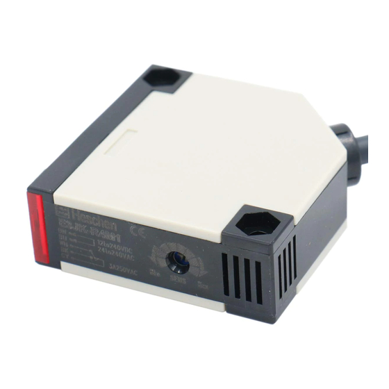
E3JK
• Built-in amplifier accepts wide supply
voltage range.
• Slim, space-saving construction mea-
sures only 50 x 50 x 17.4 mm.
• Relay outputs with long life expectan-
cy and high switching capacity (3 A,
250 V AC).
• Polarized retroreflective type available
for glossy or shiny object detection.
Sensor type
Shape
Through-beam
Retroreflective
model (with
M.S.R. function)
Retroreflective
model (without
M.S.R. function)
Diffuse-reflective
* The value within the parentheses indicates the sensing distance applied when the E39-R2 reflector is used.
Note: The UL-listed model ends with "-US". (Example: E3JK-5M1-US). Note that the DC transistor type of the E3JK is UL-unlisted.
Accessories (Order Separately)
Slits
Slit width
Sensing distance
Width 1 mmx20 mm E3JK-5##
Reflectors
Name
Sensing distance (typical)
E3JK-R2##
E3JK-R4##
Reflectors
E3JK-R2##
E3JK-R4##
Small reflector
E3JK-R2##
E3JK-R2##
Tape Reflector
E3JK-R2##
E3JK-R2##
* Values in parentheses indicate the minimum required distance between the sensor and reflector.
Note: When the reflector used is other than the supplied one, set the sensing distance to about 0.7 times of the typical example as a guideline.
E3JK
Connection
Sensing distance
method
2.5m
(3m)
Pre-wired
models
300mm
Minimum sensing
object (typical)
0.7 m
1 mm dia.
2.5 m (rated value)
4 m (rated value)
3 m
5 m
1 m (5 mm) *
750 mm (200 mm) *
1.2 m (200 mm) *
1.5 m (200 mm) *
Output form
Light ON
Relay output
5m
Dark ON
*
Light ON
Relay output
Dark ON
Light ON/Dark ON
DC transistor
(selectable)
output
*
Light ON
Relay output
Dark ON
4m
Light ON/Dark ON
DC transistor output
(5m)
(selectable)
(NPN)
Light ON
Relay output
Dark ON
Light ON/Dark ON
DC transistor output
(selectable)
(NPN)
Model
Quantity
1 pc. each for emitter
E39-S39
and receiver
(total 2 pcs.)
Model
Quantity
Attached to the E3JK-R2##.
E39-R1
1
Attached to the E3JK-R4##.
E39-R2
1
E39-R3
1
E39-RS1
E39-RS2
1
The M.S.R. function is available.
E39-RS3
Output
Model
E3JK-5M1
E3JK-5M2
E3JK-R2M1
E3JK-R2M2
NPN
E3JK-R2S3
PNP
E3JK-R2R3
E3JK-R4M1
E3JK-R4M2
E3JK-R4S3
E3JK-DS30M1
E3JK-DS30M2
E3JK-DS30S3
Remarks
(Seal type long slit)
Can be used with the through-
beam model E3JK-5##.
Remarks
---
---
1
Advertisement

Related Manuals for Omron E3JK


Summary of Contents for Omron E3JK
- Page 1 * Values in parentheses indicate the minimum required distance between the sensor and reflector. Note: When the reflector used is other than the supplied one, set the sensing distance to about 0.7 times of the typical example as a guideline.
- Page 2 Mounting Brackets Shape Model Quantity Remarks E39-L40 Supplied with E3JK Note: If a through-beam model is used, order two Mounting Brackets for the emitter and receiver respectively. Standard Photoelectric Sensors...
- Page 3 Dielectric strength 1,500 VAC at 50/60 Hz for 1 minute Destruc- Vibra- 10 to 55 Hz, 1.5 mm double amplitude for 2 hours each in X, Y, and Z directions tion tion resis- Mal- 10 to 55 Hz, 1.5 mm double amplitude for 2 hours each in X, Y, and Z directions...
- Page 4 IEC60529 IP64 structure Connection Pre-wired models (standard length: 2 m) method Weight Approx. 420 g Approx. 250 g (Packed state) Case Lens Acrylics Material Mounting Steel bracket Accessories Mounting bracket (with screws), nuts, instruction manual, reflector (retroreflective model only) E3JK...
- Page 5 Characteristic data (typical) Excess Gain Ratio vs. Setting Distance Through-beam model Retroreflective Models Diffuse-reflective E3JK-5## E3JK-R2## + E39-R1 (supplied reflector) E3JK-DS30## 1,000 Sensing object: White paper Reflector: E39-R1 Operating Operating voltage voltage Operating voltage Setting distance (mm) Setting distance (m)
-
Page 6: Output Circuit Diagram
48 VDC max. Load Drive Black Main D-ON mode circuit circuit I1 + I2 < 100 mA White Note: The output stage leakage currents are 0.1 mA max., respectively. Note: Connect to brown and blue on the emitter side. Standard Photoelectric Sensors... -
Page 7: Operation
(B) until the indicator is turned OFF, and define this position as (C). (4) The position in the middle of (A) and (C) is the optimum position. If the indicator is not turned ON by the background object at the maximum sensitivity, set the adjuster in the middle of (A) and maximum sensitivity. -
Page 8: Dimensions (Unit: Mm)
21.5 Mounting Holes R56.6 36.5 Steel 2-M6 * 1. Mounting brackets can be used on the A side (Two, M4 x 20 attached) . * 2. No sensitivity adjustment volume on the retororeflective model. 10 ˚ Mounting Holes Steel 2-M6 * 1.Mounting brackets can be used on the A side (Two, M4 x 20 attached) .