Advertisement
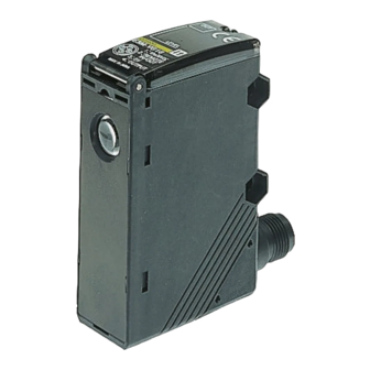
Color Mark Sensor
Detects laminated or light-dispersing objects in
stable operation without being influenced by mirror
reflection.
Double indication of the detection level and
threshold level allows easy grasp of the operating
status and easy adjustment.
Automatically sets to the optimum threshold level
while sensing objects are being conveyed and
incorporates an auto-teaching function that dis-
criminates between the mark and background and
turns ON when the mark is detected.
IP67 watertight construction with M12 rotary
connector
High response speed of 50 µs and half the size of
OMRON's conventional models.
Ordering Information
Shape
S ape
Connection
Co
Connector type
(see note)
Note: Possible to switch between vertical or horizontal connection using the M12 rotary connector.
Accessories (Order Separately)
Mounting Brackets
Shape
Sensor I/O Connectors
Shape
Single-end connector
(Straight)
(Straight)
Single-end connector
(L-shaped)
(L h
Note: For details, refer to the Sensor I/O Connectors Catalog (X065) .
ec o
Se s g d s a ce
Sensing distance
method
th d
10 3 mm
Model
E39-L131
E39-L132
Type
2 m
5 m
g
2 m
d)
5 m
Spo d a e e
Spot diameter
NPN output
1 x 4 mm
E3M-VG11
4 x 1 mm
E3M-VG21
Quantity
1
1
Cord type
4-wire cord
E3M-V
Green light
Model
PNP output
E3M-VG16
E3M-VG26
Remarks
For rear mounting
Model
XS2F-D421-D80-A
XS2F-D421-G80-A
XS2F-D422-D80-A
XS2F-D422-G80-A
1
Advertisement
Table of Contents

Related Manuals for Omron E3M-V


Summary of Contents for Omron E3M-V
- Page 1 ON when the mark is detected. IP67 watertight construction with M12 rotary connector High response speed of 50 µs and half the size of OMRON’s conventional models. Ordering Information Green light Model Shape...
-
Page 2: Specifications
E3M-V E3M-V Specifications Ratings/Characteristics Item E3M-VG11 E3M-VG21 E3M-VG16 E3M-VG26 Sensing distance 10 3 mm Spot size (W x H) 1 x 4 mm 4 x 1 mm 1 x 4 mm 4 x 1 mm Light source Green LED (525 nm) -
Page 3: Engineering Data
Incline the Sensor to detect glossy objects so that the Sensor will not 4R, 4.5/12.0 be influenced by the mirror reflection of light and to ensure the stable Yellow red 4YR, 6.0/11.5 sensing operation of the E3M-V. Yellow 5Y, 8.5/11.0 Yellow green 3GY, 6.5/10.0 Green 3G, 6.5/9.0... -
Page 4: Operation
E3M-V E3M-V Nomenclature Threshold Indicators (Red) Operation Indicator (Orange) Displays the threshold level. Lit when the output is ON. Mode Selector Detection Level Indicators (Green) Selects the mode. Displays the detection level. SET Button UP/DOWN Selector Used for teaching and threshold Increases the threshold value when adjustments. -
Page 5: Adjustment Steps
E3M-V E3M-V Adjustments Adjustment Steps 1. Install, wire, and turn ON the Photomicrosensor. 3. Make fine adjustments of the threshold level if necessary. Refer to Threshold Level Adjustments . 2. Perform teaching (mark registration). Refer to Mark Registra- tion (T eaching) . - Page 6 Input threshold level will move. Two indicators will be lit together when the threshold level is an even level. The threshold level increases. Note: Be sure to connect the E3M-V to the Programmable Con- troller as shown above. Upper threshold...
- Page 7 E3M-V Adjustments Detection Level Indicator The control output of the E3M-V will be turned ON if the detection Two-point or Auto-teaching level exceeds the threshold level. The indication of the detection A single threshold value is set between the mark (registered first) level varies with the teaching method.
- Page 8 E3M-V E3M-V Ladder Program Example Control signals are input by a ladder program as shown below. TIM000, TIM001, and TIM002 set values Input: 00000 Output: 00100 Others: IR bits Dimensions Note: All units are in millimeters unless otherwise indicated. Color Mark Sensors...
-
Page 9: Mounting Brackets
E3M-V E3M-V Accessories (Order Separately) Mounting Brackets E39-L131 Two, 4.2 dia. Material: Stainless steel (SUS304) E39-L132 4.2 dia. Material: Stainless steel (SUS304) -
Page 10: Installation
E3M-V E3M-V Sensor I/O Connectors Single-end Connector (Straight Model) XS2F-D421-D80-A (L=2 m) XS2F-D421-G80-A (L=5 m) 6 dia. 5 dia. 14.9 dia. Single-end Connector (L-shaped Model) XS2F-D422-D80-A (L=2 m) XS2F-D422-G80-A (L=5 m) 6 dia. 5 dia. Installation Sensor I/O Connector Pin No. -
Page 11: Correct Use
The E3M-V may output a single pulse when the control power sup- tion of the E3M-V may not be maintained. ply is turned OFF. If the E3M-V is connected to a timer or counter to which power is supplied from an independent power supply, the E3M-V will be more likely to output a single pulse when the control power supply is turned OFF. - Page 12 E3M-V E3M-V ALL DIMENSIONS SHOWN ARE IN MILLIMETERS. To convert millimeters into inches, multiply by 0.03937. To convert grams into ounces, multiply by 0.03527. Cat. No. E280-E1-1 In the interest of product improvement, specifications are subject to change without notice.