Table of Contents
Advertisement
Quick Links
INSTALLATION AND
OPERATION MANUAL
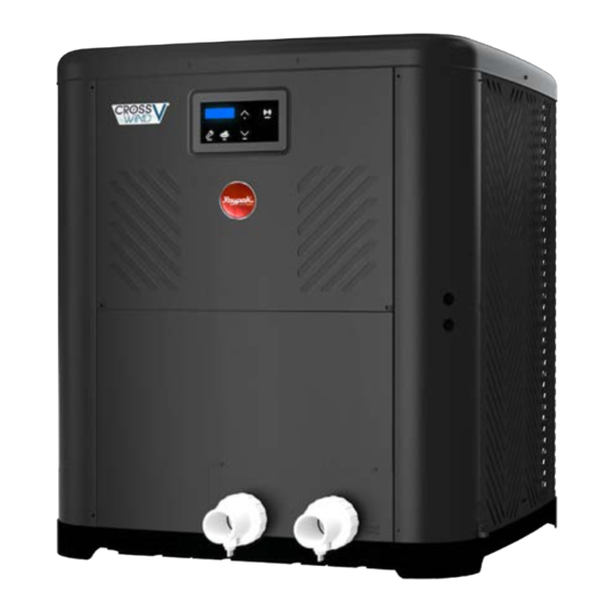
Heat Pump Pool
& Spa Heater
Models: TWPH 4550, 5550, 6550,
6550EHC, 8550, & 8550EHC
NOTICE
SCAN WITH QR EQUIPPED SMART
DEVICE FOR ONLINE MANUAL.
FOR YOUR SAFETY: Do not store or use gasoline or other flammable vapors and
liquids or other combustible materials in the vicinity of this or any other appliance.
To do so may result in an explosion or fire.
NOTE: The instructions in this manual are for the use of qualified individuals specially trained
and experienced in the installation and maintenance of this type of equipment and related system
components. Installation and service personnel are required by some states to be licensed. Persons
not qualified shall not attempt to install, service, or maintain this equipment.
This manual should be maintained in legible condition and kept adjacent to the heat pump pool heater or in a
safe place for future use.
Effective: 11-30-2023
Replaces: 08-06-2023
P/N: 100-10000496 Rev. 03
Advertisement
Table of Contents

Related Manuals for Rheem Raypak CROSSWIND V Series


Summary of Contents for Rheem Raypak CROSSWIND V Series
- Page 1 INSTALLATION AND OPERATION MANUAL Heat Pump Pool & Spa Heater Models: TWPH 4550, 5550, 6550, 6550EHC, 8550, & 8550EHC NOTICE SCAN WITH QR EQUIPPED SMART DEVICE FOR ONLINE MANUAL. FOR YOUR SAFETY: Do not store or use gasoline or other flammable vapors and liquids or other combustible materials in the vicinity of this or any other appliance.
- Page 2 QUICK START GUIDE CLEARANCES POWER † Installation Considerations Page 6. † Electrical Connections Page 10. † Installation Clearances Page 7. † Table C. Typical System Electrical Power Requirements Page 10. † Hurricane Tie Down Instructions Page 8. PIPING CONTROLS INTERFACE †...
-
Page 3: Table Of Contents
TABLE OF CONTENTS 1. WARNINGS ............. 4 16. REMOTE MODE SELECTOR ........ 31 Pay Attention to these Terms ........4 17. SEASONAL START-UP OR ANNUAL CHECK ........... 34 2. INTRODUCTION ............5 18. SUMMER SHUTDOWN.......... 34 3. WATER CHEMISTRY ..........6 19. -
Page 4: Warnings
1. WARNINGS Pay Attention to these Terms Indicates the presence of immediate hazards which will cause severe personal injury, death or substantial DANGER property damage if ignored. ndicates the presence of hazards or unsafe practices which could cause severe personal injury, death or WARNING substantial property damage if ignored. -
Page 5: Introduction
• Any service challenges present at the house/ 2. INTRODUCTION neighborhood: gated community, locked access at house, guard dog, etc. WARNING: This heat pump pool heater is an • Date of installation of the new unit electromechanical machine that incorporates pressurized refrigerant gas in a sealed system. -
Page 6: Water Chemistry
3. WATER CHEMISTRY Situate the heater carefully to minimize installation costs while providing maximum efficiency of operation, and to allow adequate service access, as follows: IMPORTANT: Corrosive water voids all • For unrestricted air intake and service access, warranties. position each side of the unit at least 1 ft (30 cm) For your health and the protection of your pool equipment, from walls, pipes and other obstructions. - Page 7 60" (1.52m) MIN AIR FLOW OUT 3 FT 12" (09.m) (0.3m) FLOW FLOW Figure 2. Installation Clearances 1. Install the WFS onto the water inlet piping as shown • When installed in areas where freezing temperatures in Figure 65. can be encountered, drain the water circuit to prevent possible freeze-up damage.
- Page 8 Figure 5. Hurricane Tie Down Instructions – Models: TWPH 4550, 5550, 6550, 6550EHC, 8550, & 8550EHC...
-
Page 9: Water Connections
5. WATER CONNECTIONS OUTLET CAUTION: The heater inlet and outlet are NOT interchangeable. They must be connected as instructed below. INLET DRAIN PLUG 1. Connect the heater in the return water line between the filter and the pool/spa. See plumbing diagrams DRAIN PLUG on page 38 (without bypass) and page 39 (with bypass). -
Page 10: Electrical Connections
external time clock overrides. Refer to the external control 7. ELECTRICAL system’s instructions, and "Remote Mode Selector", on CONNECTIONS page 31 of this manual, for installation information. An earth ground lug is located to the right-side of the water Refer to the unit rating plate below the control panel for connections. -
Page 11: Wiring Diagram
8. WIRING DIAGRAM 208V/230V Single-Phase – Heat only and Heat/Cool models OUTLET INLET 100K GN/BK GN/BK CONNECT CONNECT COIL BK/RD BK/RD BK/RD BK/RD DOWN DOWN BN/OG SERVICE SERVICE MODE MODE AMBIENT BK/BU BK/BU BK/BU BK/BU COMPONENT CODE SENSOR 10K DUAL SENSOR 100K PRESSURE SWITCH REVERSING VALVE (HEAT/COOL ONLY) -
Page 12: Heater Control Display
9. HEATER CONTROL 10. OPERATION MODES DISPLAY The user may select one of several operating modes. Each mode is selected by pressing the MODE key to cycle The heater display is located in the front panel of the heat between the modes. Each press of the MODE key selects pump, covered with a door. - Page 13 Timed Spa Mode Pool Cool Mode - Heat/Cool Models Only The control is equipped with a mode which will heat the In heat/cool models, the control is equipped with a "Pool spa to the Spa setpoint temperature for a specified period Cool Mode"...
-
Page 14: Service Menu
Example: When pool auto setpoint is set at 80°F (27°C) NOTE: If you choose to set FACTORY DEFAULTS, the and cooling deadband set at 6°F (3.5°C), the unit will pool and spa setpoints will return to their default values automatically heat the pool if the temperature drops below of 85°F (29°C) and 100°F (38°C), respectively, and the 80°F (27°C), and will automatically cool the pool if the maximum temperature settings for pool and spa will be... - Page 15 Faults History inlet temperature readings should come from a field- supplied 10K temperature sensor. Solar "Out" displays the Press the DOWN key. The "Fault History" displays up to ten temperature at the outlet of the solar heater. This reading faults in memory. The order of the faults begins with "Last comes from the Heat pump inlet sensor.
-
Page 16: Operations And Service Menu
Operations and Service Menu SERVICE SERVICE Supply Voltage Supply Voltage Supply Voltage OFF mode Run Counters Options available only 8:05PM 8:05PM in Heat/Cool models No Demand No Demand Hours Hours Available in some Cycles Cycles 8:05PM 8:05PM configurations and kits Water Temp Water Temp Faults History... -
Page 17: Program Menu
12. PROGRAM MENU ( Brownout Detect. Defaults To access the PROGRAM menu, press and hold SERVICE and MODE keys simultaneously for 7 to 10 seconds until "Language" screen appears on the display. Figure 25. Set Defaults Option This menu allows to change and reset the factory default settings, as well as providing access to the Installers and Reset Faults Schedule menus. - Page 18 Spa Setpoint Maximum Adjustment Remote Pool Mode Press the SERVICE key again. "Spa Max Temp" appears Heat on the digital display. Using the UP and DOWN keys will change the maximum temperature setting to your desired value. The control can be set to limit the maximum setpoint Figure 32.
- Page 19 Outside Lockout Temperature Adjustment INSTALLER Menu UP key to Enter To adjust the outside lockout temperature limit, press the SERVICE key and select "Outside Lockout" on the Figure 37. Installer Menu Option digital display. Use the UP and DOWN keys to set the ambient temperature at which the unit will be locked out Schedule Menu of operation.
-
Page 20: Program Menu Diagram
Program Menu Diagram Max Spa Setpoint Operation Mode Adjust Spa Spa Max Temp Spa Max Temp Temperature 65°F - 104°F Pool Timed Spa 104 F 104 F Limit DOWN DOWN SERVICE SERVICE Max Pool Setpoint SERVICE SERVICE MODE MODE MODE MODE Adjust Spa 5 sec... -
Page 21: Installer Menu
13. INSTALLER MENU • Raymote: The single-speed pump output is set to be controlled from Wi-Fi with Raymote online automation. The Installer menu shows the options to control external • Schedule: The single-speed pump output is set devices like pumps, valves, and auxiliaries, directly from to be controlled by the heat pump built-in clock and the heat pump built-in scheduler or Online Raymote schedule. - Page 22 When the variable-speed pump control is enabled, the Solar Heating Integration (Heat/Cool menu "VSP Control mode" becomes available. Use the Models Only) UP and DOWN keys to choose from the following options: To access the "Solar Heating" function, press the •Raymote: which allows Wi-Fi control using Raymote SERVICE key again.
- Page 23 The following paragraphs describe the functionality of each parameter. For more information on Solar heater Solar Deadband Solar Deadband integration and wiring, please refer to section 27, "Optional Control Outputs", on page 72. Figure 48. Solar Deadband Selection Solar Valve Position Selection (Heat/ Solar Heater Retry Time (Heat/Cool Cool Models Only) Models Only)
-
Page 24: Installer Menu Diagram
Installer Menu Diagram INSTALLER MENU OPTIONS The Installer menu shows the options to control external devices directly from the Heat Pump built-in scheduler or from Raymote app INSTALLER Menu INSTALLER Menu UP key to Enter UP key to Enter online automation. MODE MODE INSTALLER Menu... -
Page 25: Schedule Menu
14. SCHEDULE MENU Set Time with Raymote NOTE: The Schedule menu can be used to configure When the heater is connected to Wi-Fi, the clock will be automatic control of external devices directly from the updated by Raymote. Heat Pump built-in scheduler. By default, internal control Make sure to use the correct Time zone and Location in is set to “Raymote”... -
Page 26: Schedule Menu Diagram
Schedule Menu Diagram SCHEDULE Menu SCHEDULE Menu UP key to Enter UP key to Enter MODE MODE SCHEDULE Menu Set Current Time* Set Current Time Set Current Time Set Current Time Defaults Defaults 12:01 AM 12:01 AM 12:01 AM Adjust Current Time: 12:00 AM to 11:59 PM DOWN DOWN... -
Page 27: Digital Controls Operation
15. DIGITAL CONTROLS NOTE: Optional control items are not enabled by default at the factory. To activate and configure these OPERATION features, please refer to the "Installer" and "Schedule" menus. Both menus are accessible from the Program Your heat pump pool heater incorporates digital safety menu. -
Page 28: Operational Status Messages
Operational Status Messages The LCD screen displays a range of status and diagnostic messages, depending on the operating conditions. The following status messages, will be shown in pool, spa, and remote modes when no active fault conditions are present. Display Condition Demand has been satisfied and the unit is in standby. -
Page 29: Error Messages
Error Messages The following error messages are displayed in pool, spa, and remote modes. Consecutive identical faults are only stored once in the "Fault History". WARNING: Performing service on this equipment requires specialized expertise, mechanical skills, tools, and equipment. If you do not possess these, it is not recommended to attempt any service on this equipment unless following the procedures outlined in this manual. - Page 30 Minimum Run Time High Water Temperature Limit To ensure the compressor operates efficiently and has a If the compressor is demanded and the inlet water longer lifespan, the control has set a minimum run time temperature is 106°F (41°C) or higher, the control will of 3-minutes.
-
Page 31: Remote Mode Selector
16. REMOTE MODE NOTE: Typically, a remote automation controller does not supply power to the heater, it only provides a SELECTOR switching function to turn the heater On or Off. If your remote controller is supplying its own voltage to the WARNING The ability to properly perform service heater, it will not work with this heater and may damage on this equipment requires a certain level of expertise,... - Page 32 • For runs of under 30 feet (9 m), remote wiring should 7. Install the “3-wire Remote Harness” to the "P7" have stranded conductors with a minimum of 22 connector and turn power "ON" to the heater. See AWG, 600V, cable twisting 1.5" to 2.5" (3.8 to 6.4 cm) Figure 57.
- Page 33 7. Activate remote mode in the heater. Press and hold REMOTE the UP and DOWN arrow keys simultaneously for 3 to 5-seconds. POWER POWER POWER REMOTE REMOTE REMOTE USER INTERFACE USER INTERFACE USER INTERFACE REMOTE 24VAC 24VAC 24VAC SELECTOR SELECTOR SELECTOR MAIN MAIN...
-
Page 34: Seasonal Start-Up Or Annual Check
17. SEASONAL START-UP OR System Drain-Down ANNUAL CHECK 1. Turn the unit circuit breaker or disconnect switch to OFF. NOTE: At the beginning of the heating season or 2. With the pool pump OFF, close the external shut- off whenever the pool water temperature is to be raised valves and remove the drain plugs located in the several degrees, the pool pump and heat pump pool inlet and outlet water unions to allow water to drain. -
Page 35: Air Coil Cleaning
21. TROUBLESHOOTING Air Coil Cleaning Efficient operation depends on free circulation of air Before troubleshooting the system, ensure that: through the thin and tightly-spaced fins of the evaporator • All mechanical and electrical connections are secure coil(s). The evaporator must be cleaned whenever it has a and tight buildup of dirt or debris. -
Page 36: Service Call Verification
• Is airflow through the unit being obstructed? 22. SERVICE CALL Restrictions such as shrubbery, tall grass, dirty VERIFICATION coils, or any other obstruction to airflow will reduce performance. NOTE: The Service number is located on the front of the •... -
Page 37: Service Access To Heaters
Service Access to Heaters If service access to the heater is required, it is accomplished by removing the control cover panel and service access panel (Figure 62) to provide a wide access to get to (1) compressor, (2) heat exchanger, (3) thermal expansion valve (TXV), (4) reversing valve/solenoid valve (if equipped), (5) flow switch (if equipped), and (6) sensors (water, ambient and coil). -
Page 38: Plumbing Diagrams
23. PLUMBING DIAGRAMS Figure 63. Plumbing Schematic – No External Bypass (Plumb the heater AFTER the filter and before any chlorinators.) - Page 39 Figure 64. Plumbing Schematic – External Bypass (Plumb the heater AFTER the filter and before any chlorinators.)
- Page 40 Figure 65. Plumbing Schematic – Above Ground Pool Water Flow Switch Installation...
- Page 41 Figure 66. Piping for Heat Pump Pool Heater...
- Page 42 Figure 67. Piping for Multiple Heaters, Primary/Secondary...
-
Page 43: Resistance Sensor Values
24. RESISTANCE SENSOR VALUES Water Outlet, Ambient, Coil and solar sensors Inlet Water Sensor 100K Sensor Resistance Values 10K Sensor Resistance Values Temperature ºF (ºC) Resistance (Ω) Temperature ºF (ºC) Resistance (Ω) 32 (0) 325500 32 (0) 32550 41 (5) 253950 41 (5) 25340... -
Page 44: Connect To Wi-Fi With Raymote
25. CONNECT TO WI-FI WITH RAYMOTE Before initiating the provisioning process, make sure a reliable Wi-Fi access point is located near the unit or control room and a Wi-Fi network password is available. Date: _______________________________________ Wi-Fi Network Name (SSID): ______________________________________ Wi-Fi Password: _______________________________ Raymote User Registration Download Raymote app and sign up from your mobile... - Page 45 Add a New Heater to Raymote 3. Open the Raymote mobile app and log in with your user name and password. See Figure 71. 1. In the Raymote app, press the menu button located at the top left corner of the screen, then press "+ Add new device".
- Page 46 2. "Check your Device" screen will appear. Ensure to NOTE: The first time you use a new phone, the Raymote have Crosswind V heater powered and Wi-Fi signal mobile app may require you grant permission to access available in the area, then press "Start" button. See data.
- Page 47 3. In Android: Depending on your configuration, one 4. In iPhone: Raymote app will start to scan nearby heaters. If you have multiple units ready to connect, or more devices will appear on the app. Select the stand closer to the unit you want to connect first. HOTSPOT identifier that matches the unit's display as shown in Figure 77.
- Page 48 5. The "Wi-Fi setup" screen will appear. Select or enter IMPORTANT: Raymote Wi-Fi module works with 2.4GHz the Wi-Fi network you want your unit to be connected Wi-Fi signals only. to and enter the network password. See Figure 79. Ensure to have a strong signal near the heater, the Wi-Fi 6.
-
Page 49: Raymote Mobile App
Crosswind V Heater Setup 1. Your device is now connected to Wi-Fi. You can change the name of your device here. See Figure 81. Crosswind V connected! Crosswind V Figure 82. Device Setup Review 26. RAYMOTE MOBILE APP Figure 81. Name Your Unit User and Organization Settings 2. - Page 50 Figure 83. Settings - Client Accounts...
- Page 51 Figure 84. Settings - Partner Accounts...
- Page 52 Help and Tech Support 2. Tech Corner: • In-App access to Raypak Tech Corner collection. Raymote app provides direct access to technical support You can find here detailed instructions for Raypak for Raypak heaters, service kits, I&O manuals and products and service kits. See Figure 85. Raymote topics: 1.
- Page 53 Main View • Raymote organization list can handle 1 or multiple Commercial Residential Raypak heaters • The main view of Raymote display a list of the heaters equipped with Raymote. See Figure 86. added in to your Raymote Organization. • Each heater is represented by a tile with its name and an overview of the heater operation parameters.
- Page 54 Automation Raymote automation offers the ability to create automatic routines to control the heater and compatible devices like pumps and valve actuators. For details about compatible devices refer to section 27, "Optional Control Outputs", on page 72. See Figure 87 and Figure 88. ADD THE FIRST AUTOMATION ADD MORE AUTOMATION Figure 87.
- Page 55 SELECT A TRIGGER CONFIGURE TRIGGERING SELECT AN ACTION CONFIGURE THE ACTION Crosswind V Heat Pump Figure 88. Set New Automation...
- Page 56 Pool-Spa Screen NOTE: When OFF is selected, the setpoint slider is disabled. The Mode Screen contains the main controls for the heater. Operation mode and setpoint can be selected from this screen. NOTE: When unit is controlled with remote mode, the buttons OFF, Pool and Spa are disabled in the App.
- Page 57 Heater Name Water Temperature • Heater name is defined during the heater connection • The water temperature measured by the heater is and setup. It can be changed anytime from the heater displayed in this field. settings. Setpoint or Target Temperature Exit Heater •...
- Page 58 Accessories Screen NOTE: Check Section 27 "External Control Outputs" section for details of wiring and rating of the built-in The accessories screen includes the auxiliary and auxiliary relay. extended heater controls in the Raymote mobile app. These controls allow users to command an Auxiliary relay Some controls are application dependent and may not be that can be wired to turn on and off a pump, lights or water available on all units.
- Page 59 Reset Wi-Fi Credentials Reconnect to Wi-Fi Resetting the Wi-Fi is useful when the heater is trying to Follow the next steps to reconnect a heater already connect to a Wi-Fi signal that is not available or has been registered in Raymote, to a new Wi-Fi network or after a changed.
- Page 60 Figure 96. Heater Settings Screen 3. Click in the 3-dots icon again. The action menu is Figure 97. Select Reconfigure displayed. In “Actions” menu, select the option “Reconfigure” as shown in Figure 97. Figure 98. Confirm Selection...
- Page 61 4. "Check your Device" screen will appear. Ensure to have the heater powered and Wi-Fi signal available in the area, then press "Ready" button. See Figure Raymote HPPH-XXXXX Figure 99. Check your Unit 5. In Android: Depending on your configuration, one or more devices will appear on the app.
- Page 62 Press "Join" to select the displayed heater that 7. The "Wi-Fi setup" screen will appear. Select or enter matches the HOTSPOT identifier, or press "Cancel" the Wi-Fi network you want your unit to be connected to start the process again. See Figure 101. to and enter the network password.
- Page 63 11. Press the "Set up as new" button to enter unit IMPORTANT: Raymote Wi-Fi module works with 2.4GHz location, and other helpful info for future references. Wi-Fi signals only. Press the "Apply recently used profile" button to use information previously applied to other heaters. Ensure to have a strong signal near the Heater, the Wi-Fi password and to use a 2.4 GHz network.
- Page 64 Add a New User to your Organization • In Raymote Partner accounts, you can add members of your company to gain access to heaters and clients • As the Organization owner, you can add members of registered within your Organization. See Figure 107. your family, friends and others that will be able to interact with your heaters.
- Page 65 Add a Member to your Organization 3. Go to "Members" tab. Member’s list is displayed. 4. Click on the top-right icon to [Invite a New Member]. 1. In your smartphone, open the Raymote app. See Figure 109 and Figure 110. 2.
- Page 66 Client Accounts: Invite a Contractor By inviting a Contractor or Distributor, you are giving access to heaters available in your organization to a third- party organization. You can condition the access to your invited contractor as follows: • For monitoring only. •...
- Page 67 4. Organization Settings page is displayed. 5. Go to [Contractor] tab, and press [Invite Contractor]. See Figure 112. Figure 113. Enter Contractor Email and Access Level Figure 112. Click on “Invite Contractor” 7. When ready, press [Invite]. An invitation/request will IMPORTANT: Contractor must have an active Raymote be sent to the contractor's Raymote account.
- Page 68 Partner Accounts: Invite New Clients With a Raymote Partner account, “Contractor” or “Distributor”, you can: • Invite and "Manage New Clients" • Connect and configure your clients' heaters • Monitor and control residential and commercial heaters • Create automation routines and alerts for your clients •...
- Page 69 4. Fill "New Client" form with your client's email, name, and address. 5. When ready, press [Create new client]. An Raymote invite email will be sent to your new client. See Figure 116. Figure 117. Access your Client's Heaters Figure 116. Enter Client Email and Invite 6.
- Page 70 Switch to Other Organizations 3. In "Organization Settings" page, select "Switch organization" option. See Figure 119. If your Raymote organization has 1 or more sub 4. “Choose organization” screen will be displayed and it organizations, you can switch to other organization by will show all the available organizations.
- Page 71 Connectivity Troubleshooting 1. With your cellphone check that Wi-Fi signal is available next to the unit. Ensure that your Wi-Fi Wi-Fi Wi-Fi Router Extender network meets these specifications: • Supported networks - Wi-Fi 2.4GHz (802.11 b/g/n). • Password encryptions - WEP, WPA, WPA2. •...
-
Page 72: External Control Outputs
27. EXTERNAL CONTROL • Auxiliary 1 and 2 outputs. General purpose relay OUTPUTS outputs to control On/Off devices. These outputs do not supply power. Use in conjunctions with external Crosswind V heater controller offers multiple external power supply. Use additional field-supplied relays for optional outputs designed to drive 2-valve actuators, applications above 3 amperes. - Page 73 Instruction for Wiring 3. To remove the front panel, pull the bottom of the panel downward and outward, and then disconnect External Devices the wire attached to the rear of the user interface. This section outlines the general steps to wire the optimal The panel should now be free for removal.
- Page 74 6. In the case you decide to remove the grommets to connect external devices to the heater, run wires using metallic conduit or outdoor-resistant cables. Then, connect the conduit or cables to the knockout using liquid tight connectors to prevent water or dust from entering the system.
- Page 75 the pump whenever the heater requires heat (or cool). For more details about the single-speed pump control modes, please refer to section 13 of the Installer menu on page 21. 1. Check the power requirements of your single-speed pump to determine the necessary power source. Most pumps run at either 120V or 240V.
- Page 76 Protégé Variable-Speed 4. Use the harness adapter supplied in the accessory bag labeled as “single-speed pump” to connect the Pump Control Wiring field-supplied relay to the terminal of the control The Crosswind V control is designed to operate Raypak board marked as “PUMP” [P5]. Connect the other Protégé...
- Page 77 Digital Control Variable-Speed Pump Wiring To Protégé The control is designed to operate multiple brands and VS pump models of variable-speed pumps that are compatible with digital control speed selection. It features a dedicated 5-pin terminal labeled as “VAR PUMP” [P8], which provides up to 4 digital outputs of 30VDC that are compatible with the external control port of most common variable-speed pump brands in the pool industry.
- Page 78 By default, the variable-speed pump control is disabled. 2. Inside the heater's control box, use the harness However, when the variable-speed pump option is adapter labeled "Pump speed selector" that comes enabled and set to operate in the "4-speed control" mode, with the accessories bag to connect the 5-conductor the default control mode is set to command the pump cable to the control board terminal labeled "VAR...
- Page 79 Crosswind V control board Hayward VS Pump controller SINGLE VARIABLE SPEED SPEED PUMP PUMP 5-conductor cable between heater and VALVE2 VALVE1 OUTPUT OUTPUT pump controller Speed 1 Speed 2 Speed 3 Speed 4 Ground Figure 143. Hayward THP VS Pump Family Crosswind V control board Hayward VS Pump controller SINGLE...
- Page 80 Crosswind V control board Pentair VS pump SINGLE VARIABLE SPEED SPEED PUMP PUMP 5-conductor cable between heater and VALVE2 VALVE1 OUTPUT OUTPUT pump controller DC power Speed 1 supply Speed 2 Speed 3 Speed 4 Ground Figure 146. Pentair VS Pumps with IntelliComm II Interface Adapter Crosswind V control board Waterway VS pump controller SINGLE...
- Page 81 The default setting for Auxiliary Outputs 1 and 2 is to be 1. Determine the power requirements of the external controlled through the Raymote app using Wi-Fi. To use device that will be controlled or energized by the this mode, the heater must be connected to a local Wi-Fi auxiliary output(s).
- Page 82 AVIA Gas Heater Heat Pump Remote selector – Pool Auxiliary Outputs mode WPS HL1 HL2 VNT Remote selector Configure the heater to harness operate in Remote mode. Use INSTALLER menu to configure Auxiliary Output << 24 VAC signal << mode as “Auxiliary Heat ” >>...
- Page 83 Auxiliary Input Wiring The control is designed to monitor an external signal SOLAR HEAT & AUX INPUT using the "Auxiliary Input." This input has 24VAC on one terminal and uses the other terminal to receive back the 24VAC to close the auxiliary input circuit. An external COMP "normally closed"...
- Page 84 SOLAR COLLECTOR INLET OUTLET SOLAR WATER IN SENSOR (TO POOL OR SPA) FILTER PUMP CHECK VALVE SOLAR 3-WAY VALVE Figure 156. Solar Heater Components in the Piping 4. Follow the general instructions for wiring external devices and route the wires for the "Solar sensor" and SOLAR HEAT &...
- Page 85 a. For a clean installation, use ¼” male spade Water Flow Switch (WFS) Wiring terminals (.032 x .250, 18-22 AWG) for each wire The WFS comes with a limited wire length. Extend the of the WFS to mate with the WPS orange female wires as required, ensuring they do not exceed 20 ft.
-
Page 86: Replacement Parts
28. REPLACEMENT PARTS NOTE: To supply you with the correct part, it is important that you supply the heater model and serial number. Any part returned for replacement under standard company warranties must be properly tagged with a return parts tag, completely filled in with the heater serial number, model number, etc., and shipped to the Company freight prepaid. -
Page 87: Illustrated Parts List
29. ILLUSTRATED PARTS LIST MODELS 4550-8550 3-H / 4-H 8-J**... - Page 88 CALL OUT DESCRIPTION 4550 5550 6550 8550 CONTROLS TX Valve 100-10000385 100-10000386 100-10000386 100-10000387 Low Pressure Switch 100-10000633 100-10000633 100-10000633 100-10000633 High Pressure Switch 100-10000634 100-10000634 100-10000634 100-10000634 Control Cover 100-10000388 100-10000388 100-10000388 100-10000388 Inlet Temp Sensor 100K 100-10000635 100-10000635 100-10000635 100-10000635 Outlet Temp Sensor 10K...
- Page 89 NOTES Raypak, Inc., 2151 Eastman Avenue, Oxnard, CA 93030 (805) 278-5300...