Advertisement
Quick Links
INSTRUCTIONS–PARTS LIST
This manual contains important
warnings and information.
READ AND KEEP FOR REFERENCE.
INSTRUCTIONS
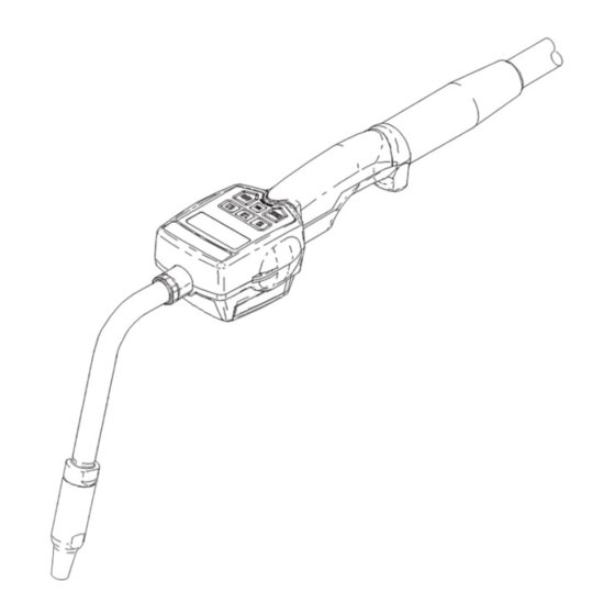
Standard
EM5
Electronic Metered
Dispense Valves
1000 psi (7 MPa, 69 bar) Maximum Working Pressure
5 gpm (18.9 lpm) Maximum Flow Rate
Factory-Set to Measure in Quarts
Series B, all Models
Model 238451
75 bend 3/8-in. rigid tube
Model 238452
3/8-in coupled flexible hose
Model 238453
15 bend 3/8-in. gear lube tube, 90 elbow
Factory-Set to Measure in Liters
Series B, all Models
Model 238454
75 bend 3/8-in. rigid tube
*
Model 238457
75 bend 3/8-in. rigid tube
Model 238455
3/8-in coupled flexible hose
*
Model 238458
3/8-in coupled flexible hose
Model 238456
15 bend 3/8-in. gear lube tube, 90 elbow
*
Model 238459
15 bend 3/8-in. gear lube tube, 90 elbow
*
Canadian Weights & Measures approved
CAUTION
This dispense valve is designed to dispense
petroleum-based lubricants and antifreeze only.
Do not dispense windshield washer solvent
with this dispense valve.
This dispense valve is designed for indoor use
only.
This dispense valve is not designed for in-line
installation. Do not install with a shut-off valve
on the outlet side of the meter. Such
installation could result in damage to the meter
housing cover.
D
97D.122550
EExia II A/B T3
GRACO INC. P.O. BOX 1441
INTRINSICALLY SAFE FOR
HAZARDOUS LOCATIONS
CLASS 1, DIV. 1, GROUP D
MINNEAPOLIS, MN 55440–1441
COPYRIGHT 1996, GRACO INC.
Graco Inc. is registered to I.S. EN ISO 9001
308487
First choice when
quality counts.
Model shown has 75 bend
3/8-in. rigid tube
Registered Design No. 1025804
Rev. L
Advertisement

Related Manuals for Graco 238451


Summary of Contents for Graco 238451
- Page 1 INTRINSICALLY SAFE FOR HAZARDOUS LOCATIONS CLASS 1, DIV. 1, GROUP D 97D.122550 EExia II A/B T3 GRACO INC. P.O. BOX 1441 MINNEAPOLIS, MN 55440–1441 COPYRIGHT 1996, GRACO INC. Graco Inc. is registered to I.S. EN ISO 9001...
- Page 2 Read all instruction manuals, tags, and labels before you operate this equipment. Use the equipment only for its intended purpose. If you are not sure, call your Graco distributor . Do not alter or modify this equipment. Use only genuine Graco parts and accessories.
- Page 3 WARNING WARNING FIRE AND EXPLOSION HAZARD Improper grounding, poor ventilation, open flames, or sparks can cause a hazardous condition and result in a fire or explosion and serious injury. Be sure the entire fluid system is properly grounded. Refer to your pump instruction manual for complete details.
- Page 4 Contact your Fig. 1 shows a typical hose reel installation. Fig. 2 Graco distributor for assistance in designing a system shows how these dispense valves can be installed on to suit your particular needs.
- Page 5 Installation Steps 2 through 6 are the Flushing Procedure . WARNING 2. Close the fluid shut-off valve (J) at each dispense PRESSURIZED EQUIPMENT HAZARD position. The equipment stays pressurized until pressure is 3. Make sure the main fluid outlet valve at the pump manually relieved.
- Page 6 Installation 10. Models 238451, 238454, and 238457 Models 238453, 238456, and 238459 This nozzle assembly can be configured two ways. See Fig. 4. See See Fig. 4. a. Thread the sealing nut (5c) onto the extension (5a) with the PTFE side facing a.
- Page 7 The dispensing system must grounded. CAUTION Proper grounding is an essential part of maintaining a Do not use Graco’s old nozzle (Part No. 203655) or safe system. any other manual shut-off nozzle on the EM5 extension. You must use the nozzle that is...
- Page 8 Notes...
- Page 9 Setup Terms Keypad Buttons The following terms are shown on the display and/or The buttons on the keypad and their functions are as used often in this instruction manual. follows (see the figure below): R–TOTAL: Resettable Total 10, 1.0, and 0.1 Displayed to show the cumulative amount that the Used to enter dispense amounts.
- Page 10 Setup Selecting Dispensing Options This is the procedure for setting or changing the resettable total, units of measurement, predetermined dispense amount, and the reset-to-zero option: 1. If the display is asleep, wake it up by pressing any button on the keypad. 2.
- Page 11 Setup Predetermined Dispense Amount Reset-to-Zero Option In this menu, you can specify an amount to be In this menu, you can set whether or not the unit will displayed when you enter the Auto Alarm dispense automatically reset to zero after two minutes of inactivity.
- Page 12 Setup Calculating the Calibration Factor Use the following tables and formulas to calculate the change to make to the calibration factor. Example of Calibration Factor Change Dispense until the display reads 1 liter (1000 ml) into a clean, calibrated, volumetric measuring flask. For increased accuracy, submerge the nozzle, and let the air settle out of the fluid for ten minutes before you note the volume.
- Page 13 Setup Calibrating the Meter 3. Press the Calibration button. NOTE: This unit has been calibrated at the factory to The calibration factor is shown on the display, as dispense lubricating oils; it should not require shown below. additional calibration during installation. If this unit will be used to dispense antifreeze, and accuracy must be greater than plus or minus 2 percent, it is recommended that you use a calibration factor of...
- Page 14 Operation Checking Segments in the Display Dispensing Fluid in Auto Alarm Mode NOTE: All buttons are disabled while fluid is being When you press the Reset button when the display is awake, the Segment Check is displayed briefly. This dispensed. display allows you to check for burned out segments in 1.
- Page 15 Operation Viewing Totals and the Calibration Factor This is the procedure for viewing the non-resettable 4. Press the Total button again. and resettable totals in the current units and for The calibration factor is shown on the display, as viewing the calibration factor. shown below.
- Page 16 Open the shut-off valve. Shut-off valve is not fully open. If the problem remains, contact your Foreign material is jammed in the Graco distributor for repair or re- metering element. placement. Displayed dispensed amount Unit needs to be calibrated for the Calibrate the meter for the fluid that is being dispensed.
- Page 17 Ensure that your flow rate is not pick-up in internal gear, or flow higher than 5 gpm. For further assis- range is too high. tance, contact your Graco distributor. Air was pumped through the line. Purge air from the line. Unit was dropped, or unit encoun- Press the Reset button at start-up.
- Page 18 Service Replacing the Battery Replacing the Filter The filter (25) is replaceable. To replace the filter, do CAUTION the following: Do not change the battery while anything is 1. Relieve the pressure. shown on the display. You must wait until the unit falls asleep and the display is blank before WARNING you remove the battery.
- Page 19 7 to 10 in-lb (0.8 to 1.1 N.m). bushing, tighten it firmly. CAUTION Do not use Graco’s old nozzle (Part No. 203655) or any other manual shut-off nozzle on the EM5 extension. You must use the nozzle that is provided with the EM5, or the meter could be...
- Page 20 191290 SWIVEL COVER, yellow 191046 TRIGGER 239949 NOZZLE ASSEMBLY 240453 KIT, valve repair For Models 238451, 238454, (includes 16a to 16e, 25, and 26 and 238457 (includes 5a to 5c) 16a* SPRING, compression 191036 .TUBE, rigid; 75 bend 16b* VALVE STEM ASSEMBLY 239829 .NOZZLE, automatic...
- Page 21 Parts Drawing Torque to 7 to 10 in-lb (0.79 to 1.13 N.m). Torque to 140 to 150 in-lb (15.8 to 16.9 N.m). Apply lubricant when reassembling. Apply thread sealant when reassembling. Torque to 20 to 25 ft-lb (27 to 34 N.m). These parts are included in Valve Repair Kit 240453, which can be ordered separately.
- Page 22 Technical Data Flow range* ......0.26 to 5 gpm Meter valve assembly pressure loss (1 to 18.9 lpm) At 1.5 gpm (5.7 lpm) with 30-weight oil Operating pressure range at 70 F (21 C)
- Page 23 Dimensional Drawing 14.0 in. (356 mm) outlet to end of swivel cover 3.25 in. (83 mm) widest cross section 2.75 in. (70 mm) keypad to bottom of cover...
- Page 24 Graco distributor to the original purchaser for use. As purchaser ’s sole remedy for breach of this warranty, Graco will, for a period of two (2) years from the date of sale, repair or replace any part of the equipment proven defective, including defects in the electronic meter control, which will be repaired or replaced for two (2) years from the date of sale.