Advertisement
Table of Contents
Safe Operation Practices • Set-Up • Operation • Maintenance • Service • Troubleshooting • Warranty
O
'
M
peratOr
s
anual
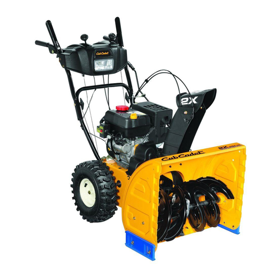
Two-Stage Snow Thrower — 526 WE
WARNING
READ AND FOLLOW ALL SAFETY RULES AND INSTRUCTIONS IN THIS MANUAL
BEFORE ATTEMPTING TO OPERATE THIS MACHINE.
FAILURE TO COMPLY WITH THESE INSTRUCTIONS MAY RESULT IN PERSONAL INJURY.
CUB CADET LLC, P.O. BOX 361131 CLEVELAND, OHIO 44136-0019
Printed In USA
Form No. 769-02601A
(June 6, 2007)
Advertisement
Table of Contents

Related Manuals for Cub Cadet 526 WE


Summary of Contents for Cub Cadet 526 WE
- Page 1 READ AND FOLLOW ALL SAFETY RULES AND INSTRUCTIONS IN THIS MANUAL BEFORE ATTEMPTING TO OPERATE THIS MACHINE. FAILURE TO COMPLY WITH THESE INSTRUCTIONS MAY RESULT IN PERSONAL INJURY. CUB CADET LLC, P.O. BOX 361131 CLEVELAND, OHIO 44136-0019 Printed In USA Form No. 769-02601A...
-
Page 2: Table Of Contents
Locate your nearest Cub Cadet Dealer at (877) 282-8684 ◊ Write us at Cub Cadet LLC • P.O. Box 361131 • Cleveland, OH • 44136-0019 This product has met the rigid safety standards of the Outdoor Power Equipment Institute and an independent testing laboratory. -
Page 3: Important Safe Operation Practices
Important Safe Operation Practices WARNING! This symbol points out important safety instructions which, if not followed, could endanger the personal safety and/or property of yourself and others. Read and follow all instructions in this manual before attempting to operate this machine. Failure to comply with these instructions may result in personal injury. - Page 4 Safe Handling of Gasoline To avoid personal injury or property damage use extreme care in handling gasoline. Gasoline is extremely flammable and the vapors are explosive. Serious personal injury can occur when gasoline is spilled on yourself or your clothes which can ignite. Wash your skin and change clothes immediately.
-
Page 5: Maintenance & Storage
Maintenance & Storage Never tamper with safety devices. Check their proper operation regularly. Refer to the maintenance and adjustment sections of this manual. Before cleaning, repairing, or inspecting machine disengage all control levers and stop the engine. Wait until the auger/impeller come to a complete stop. Disconnect the spark plug wire and ground against the engine to prevent unintended starting. -
Page 6: Assembly & Set-Up
Assembly & Set-Up Contents of Carton • One Snow Thrower • One Snow Thrower Operator’s Manual Assembly Handle Place the shift lever in the Forward-6 position Observe the lower rear area of the snow thrower to be sure both cables are aligned with roller guides before pivoting the handle upward. - Page 7 Finish securing chute control assembly to chute support bracket with wing nut and hex screw removed earlier. See See Fig. 3-4. Figure 3-4 Check that all cables are properly routed through the cable guide on top of the engine. See Fig. 3-5. Figure 3-5 Set-Up Shear Pins...
- Page 8 Tire Pressure Before operating, check tire pressure and reduce pressure in both tires to between 15 psi and 20 psi. NOTE: If the tire pressure is not equal in both tires, the machine may not travel in a straight path and the shave plate may wear unevenly.
- Page 9 Auger Control WARNING! Prior to operating your snow thrower, carefully read and follow all instructions below. Perform all adjustments to verify your snow thrower is operating safely and properly. Check the adjustment of the auger control as follows: When the auger control is released and in the disengaged “up”...
-
Page 10: Controls & Features
Controls and Features Snow thrower controls and features are described below and illustrated in Fig. 4-1. NOTE: For detailed information on all engine controls, refer to the separate Tecumseh Engine Operator’s Manual. Shift Lever The shift lever is located in the right side of the handle panel and is used to determine ground speed and direction of travel. - Page 11 Throttle Control The throttle control is located on the rear of the engine. It regulates the speed of the engine and will shut off the engine when moved into the STOP position. Primer Pressing the primer forces fuel directly into the engine’s carburetor to aid in cold-weather starting.
- Page 12 Chute Directional Control The chute directional control is located on the left side of the dash panel. • To change the direction in which snow is thrown, squeeze the button on the joy-stick and pivot the joy-stick to the right or to the left. •...
-
Page 13: Operation
Operation Starting The Engine Attach spark plug wire to spark plug. Make certain the metal loop on the end of the spark plug wire (inside the rubber boot) is fastened securely over the metal tip on the spark plug. Make certain both the auger control and drive control are in the disengaged (released) position. - Page 14 To Engage Drive With the throttle control in the Fast (rabbit) position, move shift lever into one of the six forward (F) positions or two reverse (R) positions. Select a speed appropriate for the snow conditions and a pace you’re comfortable with. Squeeze the drive control against the handle the snow thrower will move.
-
Page 15: Maintenance & Adjustment
Maintenance & Adjustments Maintenance Engine Refer to the Tecumseh Engine manual packed with your machine for all engine maintenance. Shave Plate and Skid Shoes The shave plate and skid shoes on the bottom of the snow thrower are subject to wear. They should be checked periodically and replaced when necessary. - Page 16 Auger Shaft At least once a season, remove the shear pins from the auger shaft. Spray lubricant inside the shaft and around the spacers and the flange bearings found at either end of the shaft. See Fig. 6-3. Figure 6-3 6—...
- Page 17 Drive Control When the drive control is released and in the disengaged “up” position, the cable should have very little slack. It should NOT be tight. NOTE: If excessive slack is present in the drive cable or if the snow thrower’s drive is disengaging intermittently during operation, the cable may be in need of adjustment.
-
Page 18: Service
Service Belt Replacement Auger Belt To remove and replace your snow thrower’s auger belt, proceed as follows: To prevent spillage, place a piece of plastic wrap under the gas cap and tighten securely. Remove the plastic belt cover on the front of the engine by removing the two self-tapping screws. - Page 19 Remove the belt from around the auger pulley, and slip the belt between the support bracket and the auger pulley. See Fig. 7-5. Figure 7-5 Reassemble auger belt by following instructions in reverse order. NOTE: Do not forget to reinstall the shoulder screw and reconnect the spring to the frame after installing a replacement auger belt.
-
Page 20: Friction Wheel Removal
Slip the drive belt off the pulley and between friction wheel and friction wheel disc. See Fig. 7-7. Figure 7-7 Remove and replace belt in the reverse order. NOTE: Engaging the drive control will ease reassembly of the belt. 7— s ectiOn ervice Friction Wheel Removal... - Page 21 Carefully remove the hex nut which secures the hex shaft to the snow thrower frame and lightly tap the shaft’s end to dislodge the ball bearing from the right side of the frame. See Fig. 7-9. NOTE: Be careful not to damage the threads on the shaft. Figure 7-9 Carefully position the hex shaft downward and to the left before carefully sliding the friction wheel assembly off the...
-
Page 22: Troubleshooting
Troubleshooting Troubleshooting Problem Engine fails to start Engine runs erratic Engine overheats Excessive vibration Loss of power Unit fails to propel itself Unit fails to discharge snow Cause Choke not in ON position. Spark plug wire disconnected. Fuel tank empty or stale fuel. Engine not primed. -
Page 23: Replacement Parts
Replacement Parts Component (800) 965-4CUB Phone to order replacement parts or a complete Parts Manual (have your full model number and serial number ready). Parts Manual downloads are also available free of charge at www.cubcadet.com. Part Number and Description 929-0071 Extention Cord, 110V 954-04050 Auger Drive Belt 754-0367 Wheel Drive Belt 684-04153 Friction Wheel Assembly 935-04054 Friction Wheel Rubber 925-04213 Lamp, 12.5V, 37.5W 738-04124A Shear Pin, 1.50 714-04040 Bow-tie Cotter Pin 790-00141 Stainless Steel Slide Shoe, Deluxe 731-2643 Chute Clean-out Tool 790-00148 Stainless Steel Shave Plate, 26” TC-35062 759-3338 Champion RJ19LM Resistor Spark Plug... - Page 24 MANUFACTURER’S LIMITED WARRANTY FOR The limited warranty set forth below is given by Cub Cadet LLC with respect to new merchandise purchased and used in the United States, its possessions and territories, and by MTD Products Limited with respect to new merchandise purchased and used in Canada and/or its territories and possessions.