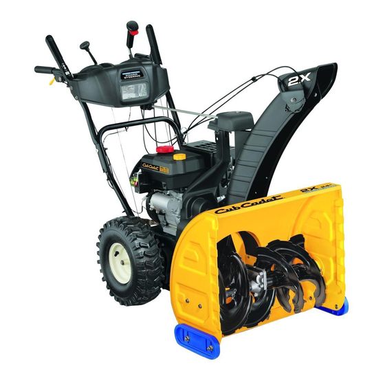
Cub Cadet 524 SWE Operator's Manual
Two stage snow thrower
Hide thumbs
Also See for 524 SWE:
- Operator's manual (28 pages) ,
- Illustrated parts list (12 pages) ,
- Specifications (2 pages)
Table of Contents
Advertisement
Safe Operation Practices • Set-Up • Operation • Maintenance • Service • Troubleshooting • Warranty
O
'
M
peratOr
s
anual
Two Stage Snow Thrower — 524 WE, 524 SWE,
526 SWE, 528 SWE & 528 SW
WARNING
READ AND FOLLOW ALL SAFETY RULES AND INSTRUCTIONS IN THIS MANUAL
BEFORE ATTEMPTING TO OPERATE THIS MACHINE.
FAILURE TO COMPLY WITH THESE INSTRUCTIONS MAY RESULT IN PERSONAL INJURY.
CUB CADET LLC, P.O. BOX 361131 CLEVELAND, OHIO 44136-0019
Printed In USA
Form No. 769-06030
(June 30, 2010)
Advertisement
Table of Contents

Related Manuals for Cub Cadet 524 SWE


Summary of Contents for Cub Cadet 524 SWE
- Page 1 Safe Operation Practices • Set-Up • Operation • Maintenance • Service • Troubleshooting • Warranty ’ peratOr anual Two Stage Snow Thrower — 524 WE, 524 SWE, 526 SWE, 528 SWE & 528 SW WARNING READ AND FOLLOW ALL SAFETY RULES AND INSTRUCTIONS IN THIS MANUAL BEFORE ATTEMPTING TO OPERATE THIS MACHINE.
-
Page 2: Table Of Contents
Visit us on the web at www.cubcadet.com ◊ Call a Customer Support Representative at (800) 965-4CUB ◊ Locate your nearest Cub Cadet Dealer at (877) 282-8684 ◊ Write to Cub Cadet LLC • P.O. Box 361131 • Cleveland, OH • 44136-0019... -
Page 3: Safe Operation Practices
Important Safe Operation Practices WARNING! This symbol points out important safety instructions which, if not followed, could endanger the personal safety and/or property of yourself and others. Read and follow all instructions in this manual before attempting to operate this machine. Failure to comply with these instructions may result in personal injury. - Page 4 Safe Handling of Gasoline Never run an engine indoors or in a poorly ventilated area. Engine exhaust contains carbon monoxide, an odorless To avoid personal injury or property damage use extreme care and deadly gas. in handling gasoline. Gasoline is extremely flammable and the Do not operate machine while under the influence of vapors are explosive.
-
Page 5: Clearing Clogged Discharge Chute
Clearing a Clogged Discharge Chute According to the Consumer Products Safety Commission (CPSC) and the U.S. Environmental Protection Agency (EPA), Hand contact with the rotating impeller inside the discharge this product has an Average Useful Life of seven (7) years, chute is the most common cause of injury associated with snow or 60 hours of operation. -
Page 6: Safety Symbols
Safety Symbols This page depicts and describes safety symbols that may appear on this product. Read, understand, and follow all instructions on the machine before attempting to assemble and operate. Symbol Description READ THE OPERATOR’S MANUAL(S) Read, understand, and follow all instructions in the manual(s) before attempting to assemble and operate WARNING—... -
Page 7: Assembly & Set-Up
Assembly & Set-Up Contents of Carton • One Snow Thrower • Two Replacement Auger Shear Pins • One Product Registration Card • One Snow Thrower Operator’s • Hex Rod • Chute Assembly Manual Assembly Remove all loose parts before assembling. Handle Assembly Place the shift lever in the Forward-6 position Observe the lower rear area of the snow thrower to be sure... - Page 8 Insert hex rod into chute control head. Push rod as far into Squeeze the trigger on the joystick and rotate the chute by chute control head as possible, keeping the holes in the hand to face forward. The holes in the chute control input hex rod pointing upward.
-
Page 9: Set-Up
Insert the hex rod into the pinion gear below the joystick. Finish securing chute control head to chute support Make sure to line up the hole in the hex rod with the arrow bracket with wing nut, clevis pin, and bow-tie cotter pin on the pinion gear. -
Page 10: Skid Shoes
Adjustments Chute Clean-Out Tool The chute clean-out tool is fastened to the top of the auger Skid Shoes housing with a mounting clip and a cable tie at the factory. Cut The snow thrower skid shoes are adjusted upward at the factory the cable tie before operating the snow thrower. - Page 11 Auger Control Chute Assembly NOTE: Chutes on models with 4-Way Chute Control are WARNING! Prior to operating your snow thrower, controlled by the Chute Directional Control. See Fig. 4-1. carefully read and follow all instructions below. The distance snow is thrown can be adjusted by changing the Perform all adjustments to verify your snow thrower angle of the chute assembly.
-
Page 12: Controls
Controls and Features Drive Control Shift Lever Chute Directional Control Auger Control Headlight Steering Trigger Control Chute Assembly Clean Out Tool Augers Skid Shoe Figure 4-1 Skid Shoes Snow thrower controls and features are described below and illustrated in Fig. 4-1. Position the skid shoes based on surface conditions. - Page 13 Auger Control Chute Clean-Out Tool WARNING! Never use your hands to clear a clogged chute assembly. Shut off engine and remain behind handles until all moving parts have stopped before unclogging. The chute clean-out tool is conveniently fastened to the rear of the auger housing with a mounting clip.
- Page 14 2-Way Chute Directional Control (if so equipped) The chute directional control is located on the left side of the dash panel. • To change the direction in which snow is thrown, squeeze the button on the joy-stick and pivot the joy-stick to the right or to the left.
-
Page 15: Operation
Operation Starting and Stopping the Engine Refer to the Engine Operator’s Manual packed with your snow thrower for instructions on starting and stopping the engine. To Engage Drive With the throttle control in the Fast (rabbit) position, move shift lever into one of the six forward (F) positions or two reverse (R) positions. -
Page 16: Maintenance & Adjustment
Maintenance & Adjustments Maintenance Lubrication Engine Wheels Refer to the Engine Operator’s Manual. At least once a season, remove both wheels. Clean and coat the axles with a multipurpose automotive grease before reinstalling Shave Plate and Skid Shoes wheels. The shave plate and skid shoes on the bottom of the snow Auger Shaft thrower are subject to wear. - Page 17 Adjustments Gear Shaft The gear (hex) shaft should be lubricated at least once a season Shift Cable or after every twenty-five (25) hours of operation. If the full range of speeds (forward and reverse) cannot be Allow the engine to run until it is out of fuel. achieved, adjust the shift cable as follows: Carefully pivot the snow thrower up and forward so that it Place the shift lever in the fastest forward speed position.
- Page 18 Drive Control Chute Control Rod When the drive control is released and in the disengaged “up” To adjust the chute control rod, proceed as follows: position, the cable should have very little slack. It should NOT be Remove the cotter pin from the hole closest to the chute tight.
-
Page 19: Service
Service Belt Replacement Carefully pivot the snow thrower up and forward so that it rests on the auger housing. Auger Belt Remove the frame cover from the underside of the snow thrower by removing the self-tapping screws which secure To remove and replace your snow thrower’s auger belt, proceed it. - Page 20 Remove the belt from around the auger pulley, and slip the Drive Belt belt between the support bracket and the auger pulley. To remove and replace your snow thrower’s drive belt, proceed See Fig. 7-5. as follows: To prevent spillage, remove all fuel from tank by running engine until it stops.
-
Page 21: Friction Wheel Removal
Remove and replace belt in the reverse order. Friction Wheel Inspection (524 SWE, 526 SWE, 528 SWE & 528 SW) If the snow thrower fails to drive with the drive control engaged, and performing the drive control cable adjustment fails to correct the problem, the friction wheel may need to be replaced. - Page 22 Carefully remove the hex nut which secures the hex shaft Follow the previous steps in reverse order to reassemble to the snow thrower frame and lightly tap the shaft’s end to components. If you’re disassembling the friction wheel and dislodge the ball bearing from the right side of the frame. replacing only the rubber ring, proceed as follows: See Fig.
-
Page 23: Troubleshooting
Troubleshooting Problem Cause Remedy Engine fails to start Choke not in CHOKE position. Move choke to CHOKE position. Spark plug wire disconnected. Connect wire to spark plug. Fuel tank empty or stale fuel. Fill tank with clean, fresh gasoline. Engine not primed. Prime engine as instructed in the Engine Operator’s Manual. -
Page 24: Replacement Parts
Component Part Number and Description 929-0071A Extension Cord, 110V 954-04050 Auger Drive Belt (524 WE & 524 SWE) 954-04260 Wheel Drive Belt (524 WE & 524 SWE) 954-04195 Auger Drive Belt (526 SWE & 528 SWE & 528 SW) 954-04201A Wheel Drive Belt (526 SWE &... -
Page 25: Attachments
Attachments & Accessories The following attachments and accessories are available for your Cub Cadet snow thrower. See your Cub Cadet dealer or the retailer from which you purchased your snow thrower for information regarding price and availability. Model Number Description... - Page 26 Notes...
- Page 27 11 — n ectiOn Otes...
- Page 28 MANUFACTURER’S LIMITED WARRANTY FOR SNOW THROWERS The limited warranty set forth below is given by Cub Cadet LLC with b. Cub Cadet does not extend any warranty for products sold or respect to new merchandise purchased and used in the United States,...