Cub Cadet SWE 528 Operator's Manual
Two-stage
Hide thumbs
Also See for SWE 528:
- Operator's manual (32 pages) ,
- Illustrated parts list (12 pages) ,
- Specifications (2 pages)
Table of Contents
Advertisement
Safety • Assembly • Operation • Adjustments • Maintenance • Troubleshooting • Parts Lists • Warranty
OPERATOR'S MANUAL
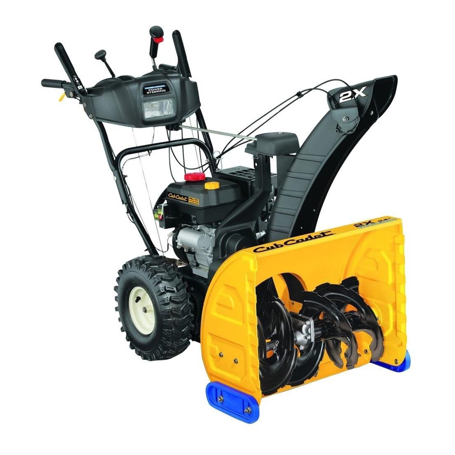
Two-Stage Snow Thrower — Model SWE 528
IMPORTANT
READ SAFETY RULES AND INSTRUCTIONS CAREFULLY BEFORE OPERATION
Warning: This unit is equipped with an internal combustion engine and should not be used on or near any unimproved forest-covered, brush-
covered or grass-covered land unless the engine's exhaust system is equipped with a spark arrester meeting applicable local or state laws (if any).
If a spark arrester is used, it should be maintained in effective working order by the operator. In the State of California the above is required by law
(Section 4442 of the California Public Resources Code). Other states may have similar laws. Federal laws apply on federal lands. A spark arrester
for the muffler is available through your nearest engine authorized service dealer or contact the service department, P.O. Box 361131 Cleveland,
Ohio 44136-0019.
CUB CADET LLC, P.O. BOX 361131 CLEVELAND, OHIO 44136-0019
FORM NO. 769-01791A
PRINTED IN U.S.A.
06/02/2006
Advertisement
Table of Contents

Related Manuals for Cub Cadet SWE 528


Summary of Contents for Cub Cadet SWE 528
- Page 1 (Section 4442 of the California Public Resources Code). Other states may have similar laws. Federal laws apply on federal lands. A spark arrester for the muffler is available through your nearest engine authorized service dealer or contact the service department, P.O. Box 361131 Cleveland, Ohio 44136-0019. CUB CADET LLC, P.O. BOX 361131 CLEVELAND, OHIO 44136-0019 FORM NO. 769-01791A PRINTED IN U.S.A.
-
Page 2: Table Of Contents
Table of Contents Maintaining Your Snow Thrower ... 14 Off-Season Storage ... 20 Troubleshooting ... 21 Illustrated Parts List ... 22 Warranty ... 31-32 www.cubcadet.com DEALER LOCATOR PHONE NUMBER: 877-282-8684 Customer Support CUB CADET LLC P. O. BOX 361131 CLEVELAND, OH 44136... -
Page 3: Safety Labels
A chute clean-out tool is fastened to the top of the auger housing with a mounting clip. The tool is designed to clear a chute assembly of ice and snow. This item is fastened with a cable tie at the factory. Cut the cable tie before operating the snow thrower. -
Page 4: Safe Operation Practices
DANGER: This machine was built to be operated according to the rules for safe operation in this manual. As with any type of power equipment, carelessness or error on the part of the operator can Safe result in serious injury. This machine is capable of amputating hands and feet and throwing objects. Failure to observe the following safety instructions could result in serious injury or death. - Page 5 Operation 1. Do not put hands or feet near rotating parts, in the auger/impeller housing or chute assembly. Contact with the rotating parts can amputate hands and feet. 2. The auger/impeller control lever is a safety device. Never bypass its operation. Doing so makes the machine unsafe and may cause personal injury.
-
Page 6: Setting Up Your Snow Thrower
Setting Up Your Snow Thrower All references in this manual to the left or right side of the snow thrower is from the operating position only. Exceptions, if any, will be specified. IMPORTANT: This unit is shipped with the engine full of oil. -
Page 7: Tire Pressure
CAUTION: Prior to operating your snow thrower, refer to Auger Control Test in Operation section. Read and follow all instructions carefully, and perform all adjustments to verify your snow thrower is operating safely and properly. Shear Pin Storage Holes are located in the plastic dash panel for convenient shear pin storage. -
Page 8: Operating Your Snow Thrower
Operating Your Snow Thrower WARNING Read, understand, and follow all instructions and warnings on the machine and in this manual before operating. Use extreme care when handling gasoline. Now that you have setup your snow thrower, it’s Gasoline is extremely important to become acquainted with its controls and flammable and the vapors features. -
Page 9: Auger Control
Auger Control The auger control is located on the left handle. Squeeze the control grip against the handle to engage the augers and start snow throwing action. Release to stop. Drive Control/ Auger Control Lock The drive control is located on the right handle. Squeeze the control grip against the handle to engage the wheel drive. -
Page 10: Starting The Engine
Gas & Oil Fill-Up Service the engine with gasoline and oil as instructed in the Tecumseh Engine manual packed separately with your snow thrower. Read instructions carefully. Starting The Engine 1. Attach spark plug wire to spark plug. Make certain Operating the metal loop on the end of the spark plug wire (inside the rubber boot) is fastened securely over the... - Page 11 To Engage Drive 1. With the engine running near top speed, move shift lever to one of six FORWARD positions or two REVERSE positions. Select a speed appropriate for the snow conditions that exist. 2. Squeeze drive control against the right handle and the snow thrower will move.
-
Page 12: Making Adjustments
Making Adjustments WARNING Read, understand, and follow all instructions and warnings on the machine and in this manual before operating. Never attempt to make any adjustments while the engine is running, except where specified in operator’s manual. This Operator’s Manual may cover a range of product specifications for various models. - Page 13 You can also check the adjustment as follows: 1. With the snow thrower tipped forward (be certain to drain gasoline or place plastic film under the gas cap if the snow thrower has already been operated), remove the frame cover underneath the snow thrower by removing the self-tapping screws.
-
Page 14: Maintaining Your Snow Thrower
Maintaining Your Snow Thrower WARNING Always stop engine, disconnect spark plug, and ground against engine before performing any type of maintenance on your machine. IMPORTANT: Avoid oil spillage on rubber friction wheel and aluminum drive plate. Do not overfill the gear case. Damage to the seals could result. -
Page 15: Replacing Belt
Shave Plate and Skid Shoes The shave plate and skid shoes on the bottom of the snow thrower are subject to wear. Check these periodi- cally and replace as necessary. Replacing Skid Shoe 1. Remove four carriage bolts, hex nuts, and washers which attach the two skid shoes to the snow thrower on each side of the housing. - Page 16 Maintaining Your Snow Thrower WARNING Always stop engine, disconnect spark plug, and ground against engine before performing any type of maintenance on your machine. 1. Roll auger belt off the pulley as shown in Figure 23. 2. a. Turn the shoulder screw a half a turn and slide it out b.
-
Page 17: Drive Belt
Cadet Service Dealer if your friction wheel rubber needs to be replaced or phone Customer Support as instructed on page 2 for information on ordering a Cub Cadet Service Manual. Also, refer to the Drive Control adjustment in the “Mak- ing Adjustments”... -
Page 18: Off-Season Storage
If the snow thrower will not be used for 30 days or longer, or if it is the end of the snow season when the last pos- sibility of snow is gone, the equipment needs to be stored properly. Follow storage instructions below to ensure top performance from the snow thrower for many more years. -
Page 19: Troubleshooting
1. Stop engine immediately and discon- nect spark plug wire. Tighten all bolts and nuts. If vibration continues, have unit serviced by a Cub Cadet Service Dealer. 1. Connect and tighten spark plug wire. 2. Remove ice and snow from gas cap. - Page 20 22 55...
-
Page 21: Parts List
731-2643 Clean-Out Tool 712-04065 Flange Lock Nut 756-0981B Flat Idler Pulley 710-0347 Hex Bolt, 3/8-16 x 1.75 790-00080A Auger Idler Bracket 736-0174 Wave Washer 738-0281 Shoulder Screw 738-0143 Shoulder Screw 790-00075 Bearing Housing 10. 726-04012 Push Nut 11. 712-04063 Flange Lock Nut, 5/16-18 12. - Page 23 684-04106B Handle Engagement Assembly RH 738-04194 Flange Shoulder Screw 731-04894B Lock Plate 711-04287 Pivot Rod 735-0199A Rubber Bumper 710-04354 Screw, 1/4-20 x.375 731-04896A Clutch Lock Cam 712-04081A Shoulder Nut, 1/4-20 725-04314 Wire Harness (Not Shown) 10. 725-1649 Light Socket 11. 720-0274 Handle Grip 12.
- Page 24 6 17...
- Page 25 710-1652 AB Screw, 1/4-20 x 0.625 731-05353 Belt Cover 732-0705 Cable Guide 711-1268B Actuator Shaft 746-04229 Drive Clutch Cable 732-04345 Extension Spring 790-00207A Drive Clutch Cable Guide Bracket 684-04156 Shift Rod Assembly 750-04474 Axle Support Tube 10. 714-0126 Hi Pro Key 11.
- Page 26 NOTES Use this page to make notes and write down important information.
-
Page 27: Warranty
MANUFACTURER’S LIMITED COMMERCIAL WARRANTY FOR: The limited warranty set forth below is given by Cub Cadet LLC with re- spect to new merchandise used for commercial purposes and purchased and used in the United States and/or its territories and possessions, and... - Page 28 MANUFACTURER’S LIMITED WARRANTY FOR The limited warranty set forth below is given by Cub Cadet LLC with respect to new merchandise purchased and used in the United States, its possessions and territories, and by MTD Products Limited with respect to new merchandise purchased and used in Canada and/or its territories and possessions.