Table of Contents
Advertisement
Quick Links
USA
CANADA
For Service Center
Assistance Call:
3108162.029 31081
INSTALLATION & OPERATING
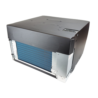
SELF-CONTAINED HEAT PUMP FOR TENT
CAMPERS & SMALL TRAVEL TRAILERS
THIS UNIT IS DESIGNED FOR OEM INSTALLATION
ALL INITIAL INSTALLATIONS MUST BE APPROVED BY THE SALES DEPT.
This manual must be read and un-
derstood before installation, adjust-
ment, service or maintenance is
performed. This unit must be in-
stalled by a qualified service tech-
nician. Modification of this product
can be extremely hazardous and
could result in personal injury or
property damage.
INSTRUCTIONS
IMPORTANT:
RECORD THIS UNIT INFORMATION FOR FUTURE
REFERENCE:
ROTARY COMPRESSOR
SYSTEM MODEL
C
US
Lire et comprendre ce manuel avant
de procéder à l'installation, à des
réglages, de l'entretien ou des
réparations. L'installation de cet
appareil doit être effectuée par un
réparateur qualifié. Toute modification
de cet appareil peut être extrêmement
dangereuse et entraîner des blessures
ou dommages matériels.
41001.602
41001
MODEL
Advertisement
Table of Contents

Related Manuals for Dometic Duo-Therm COOL CAT 41001.602


Summary of Contents for Dometic Duo-Therm COOL CAT 41001.602
- Page 1 RECORD THIS UNIT INFORMATION FOR FUTURE REFERENCE: SELF-CONTAINED HEAT PUMP FOR TENT CAMPERS & SMALL TRAVEL TRAILERS ROTARY COMPRESSOR SYSTEM MODEL 41001 THIS UNIT IS DESIGNED FOR OEM INSTALLATION ALL INITIAL INSTALLATIONS MUST BE APPROVED BY THE SALES DEPT. CANADA For Service Center Assistance Call: Lire et comprendre ce manuel avant...
-
Page 2: Safety Instructions
INDEX SAFETY INSTRUCTIONS RECOGNIZE SAFETY INFORMATION UNDERSTAND SIGNAL WORDS WARNING: means if the safety information is not followed someone could be injured or killed and/or damage to equipment could occur. CAUTION: means if the safety information is not followed someone might be injured or killed and/or damage to equipment might occur. -
Page 3: Specifications & Wiring Diagram
1. SPECIFICATIONS & WIRING DIAGRAM SPECIFICATIONS MODEL NUMBER 41001 WIRING DIAGRAM... -
Page 4: Installation Instructions
2. INSTALLATION INSTRUCTIONS A. PRECAUTIONS Improper installation may damage equipment, could endanger life, cause serious injury and/or property damage. C. THERMOSTAT LOCATION D. VENTILATION REQUIREMENTS B. CHOOSING THE PROPER LOCATION FOR THE HEAT PUMP... -
Page 5: Power Supply Connection
F. POWER SUPPLY CONNECTION E. HEAT PUMP PREPARATION HEAT PUMP LOW VOLTAGE WIRES AND THERMOSTAT CONNECTIONS HEAT PUMP LEADS THERMOSTAT LEADS... -
Page 6: Heat Pump Installation
G. HEAT PUMP INSTALLATION H. DUCT, GRILLES AND REGISTERS INSTALLATION DRAWING... -
Page 7: General Information
3. OPERATING INSTRUCTIONS A. GENERAL INFORMATION B. THERMOSTAT OPERATION Summer Summer Summer/Winter Winter Summer Winter C. DRAIN PLUG AND FROST PREVENTION... -
Page 8: Maintenance
4. MAINTENANCE 5. SERVICE Unit Does Not Operate:...