Table of Contents
Advertisement
REVISION C
Form No. 3314102.000 08/16
(French 3314103.000_C)
©2016 Dometic Corporation
LaGrange, IN 46761
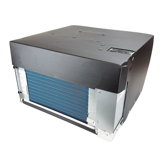
Self-Contained Unit
Description
Heat Pump
This Unit is designed for OEM installation. All initial installations must be approved by Dometic Corporation.
USA
SERVICE OFFICE
Dometic Corporation
1120 North Main Street
Elkhart, IN 46514
RECORD THIS INFORMATION FOR FUTURE
REFERENCE:
Model Number
Serial Number
Date Purchased
Model
441003.701
441003A701
Read these instructions carefully. These
instructions MUST stay with this product.
CANADA
Dometic Corporation
46 Zatonski, Unit 3
Brantford, ON N3T 5L8
CANADA
SERVICE CENTER &
DEALER LOCATIONS
Please Visit:
www.eDometic.com
Advertisement
Table of Contents

Related Manuals for Dometic 441003.701


Summary of Contents for Dometic 441003.701
- Page 1 Self-Contained Unit Description Model Heat Pump 441003.701 441003A701 This Unit is designed for OEM installation. All initial installations must be approved by Dometic Corporation. Read these instructions carefully. These instructions MUST stay with this product. CANADA SERVICE CENTER & REVISION C...
-
Page 2: Table Of Contents
Vehicle (hereinafter referred to as RV) during the time it is manufactured. It is recommended that the RV interior space be essentially one undivided space. Use these instructions to ensure a properly installed, and properly functioning product. Dometic Corporation reserves the right to modify appearances and specifications without notice. TABLE OF CONTENTS INTRODUCTION ..................................2 DOCUMENT SYMBOLS ................................2... -
Page 3: Important Safety Instructions
● This product MUST be [installed / serviced] by a qualified service technician. ● Do NOT modify this product in any way. Modifica- tion can be extremely hazardous. ● Do NOT add any devices or accessories to this product except those specifically authorized in writing by Dometic Corporation. -
Page 4: General Information
For a more permanent solution to high heat gain, acces- sories like Dometic outdoor patio and window awnings will reduce heat gain by removing the direct sun. They also add a nice area to enjoy company during the cool of the evening. -
Page 5: Specifications
** For wire length over 24 ft., consult the National Electrical Code for proper sizing. *** Dometic Corporation gives GENERAL guidelines for generator requirements. These guidelines come from experiences people have had in actual applications. When sizing the generator, the total power usage of your RV must be considered. -
Page 6: Installation Instructions
Opening For operate properly; however, these alter- 14″ Front Grille nate configurations and methods MUST be approved by Dometic Corporation. Grilles And Registers 1″ Required Above Floor The following accessories are available in various kits to Line For Attaching Front simplify installations. -
Page 7: Wiring Requirements
INSTALLATION INSTRUCTIONS I n a travel trailer installation, if within a 5. Avoid locations close to supply registers and the air from them. cabinet or in the ceiling, ducting may be required. Installing Unit 5. Interior access openings should be prepared as shown. -
Page 8: Wiring System
INSTALLATION INSTRUCTIONS I f your cabinet space is between 20″ and c. Connect the previously run –12 Vdc supply wire to both the black wire protruding from 23-1/2″ deep, the metal duct extension is NOT needed. Attach the registers directly the unit and to the wire of the three wire cable that goes to the thermostat 12V–... -
Page 9: System Checkout
INSTALLATON INSTRUCTIONS ● Red/White wire to the 12V+ terminal ● Black wire to the 12V– terminal ● Orange wire to the "COMMS" terminal 6. Inspect all connections to make sure they are tight and not touching any other terminals or wires. -
Page 10: Unit Wiring Diagram - Later Version
WIRING DIAGRAM Unit Wiring Diagram - Later Version FIG. 8 INSTALLATION COMPONENTS FIG. 9 Outside Grille Rain Shield Top Unit Duct Extension Rain Shield 120 Vac Junction Box Cover Register Strain Relief Data Plate Thermostat Connection 12 Vdc & Furnace Connection Filter Inside Grille (Direct Discharge Shown)