
Related Manuals for Mitsubishi alpha 2


Summary of Contents for Mitsubishi alpha 2
- Page 1 α 2 Simple Application Controller HARDWARE MANUAL HARDWARE-HANDBUCH MANUEL DU MATÉRIEL MANUALE HARDWARE MANUAL DE HARDWARE MASKINVARUHANDBOK РУКОВОДСТВО ПО АППАРАТНОЙ ЧАСТИ...
- Page 2 • electrical engineer who is qualified and trained to local and national standards which apply to the installation site. If in doubt about the operation or use of the α/α2 Series Controller please consult the nearest Mitsubishi • Electric distributor.
- Page 3 α 2 Simple Application Controllers α 2 Simple Application Controller Hardware Manual Manual number: JY992D97301 Manual revision: H Date: 3/2008 ENG-i...
- Page 4 α 2 Simple Application Controllers ENG-ii...
- Page 5 2 Simple Application Controllers FAX BACK Mitsubishi has a world wide reputation for its efforts in continually developing and pushing back the frontiers of industrial automation. What is sometimes overlooked by the user is the care and attention to detail that is taken with the documentation. However, to continue this process of improvement, the comments of the Mitsubishi users are always welcomed.
- Page 6 α 2 Simple Application Controllers ENG-iv...
- Page 7 α 2 Simple Application Controllers Guidelines for the Safety of the User and Protection of equipment α This manual provides information for the use of the 2 Series Controllers. The manual has been written to be used by trained and competent personnel. The definition of such a person or persons is as follows;...
- Page 8 α 2 Simple Application Controllers • Under no circumstances will Mitsubishi Electric be liable or responsible for any consequential damage that may arise as a result of the installation or use of this equipment. • All examples and diagrams shown in this manual are intended only as an aid to understanding the text, not to guarantee operation.
- Page 9 α 2 Simple Application Controllers Abbreviations The following definitions or abbreviations will be used throughout this manual. • The AL-PCS/WIN-E software will be referred to as the VLS software or the programming software. α α α • The 2 Series Simple Application Controller may be referred to as the 2 series, the series controller or the main module.
- Page 10 α 2 Simple Application Controllers ENG-viii...
-
Page 11: Table Of Contents
α 2 Simple Application Controllers Table of Contents Guidelines of Safety ..............ENG-v 1. Introduction..................ENG-1 α 1.1 Special Features of the 2 Series System............ ENG-2 1.2 Available Models ................... ENG-3 1.3 Dimensions and Each Part Name ..............ENG-4 1.4 System Configuration ..................ENG-6 1.5 Version Up List .................... - Page 12 α 2 Simple Application Controllers 7. AL-232CAB ...................ENG-32 7.1 Introduction....................ENG-32 7.1.1 External Dimensions ..................ENG-32 7.2 Connected to AL-232CAB cable..............ENG-33 8. AL2-GSM-CAB ................ENG-36 8.1 Introduction....................ENG-36 8.1.1 External Dimensions ..................ENG-36 8.1.2 System Configuration with using AL2-GSM-CAB..........ENG-37 8.2 Installation ....................
- Page 13 α 2 Simple Application Controllers 12.AL2-2PT-ADP................ENG-60 12.1 Introduction....................ENG-61 12.1.1 External Dimensions ..................ENG-61 12.2 System Configuration .................. ENG-61 12.3 Specification ....................ENG-62 12.4 Wiring and Installation ................. ENG-64 12.4.1 Installation ......................ENG-64 12.4.2 Wiring ........................ ENG-65 12.4.3 Choosing a Temperature Scale................. ENG-66 12.4.4 Offset Adjustment ....................
- Page 14 α 2 Simple Application Controllers ENG-xii...
-
Page 15: Introduction
However, the 2 series is not designed to be used in the following applications. Please contact a Mitsubishi distributor for more information. - Applications where high reliabilities such as nuclear power control, railway facilities, airline facilities, vehicles, combustion equipment, and medical equipment are required. -
Page 16: Special Features Of The
α Introduction 1 2 Simple Application Controllers α Special Features of the 2 Series System 1) Display message and Function Block data α 2 series can display the state of operation and the alarm on the LCD display as a message. -
Page 17: Eng
α Introduction 1 2 Simple Application Controllers Available Models Table 1.2:Main Units Input Output MASS Power Dimensions Model (Weight) Supply mm (inches) Type Number Type Number kg (lbs) 100 - 240V 100 - 240V 0.21 71.2 x 90 x 52 AL2-10MR-A RELAY (0.47) -
Page 18: Dimensions And Each Part Name
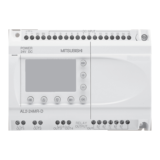
α Introduction 1 2 Simple Application Controllers Dimensions and Each Part Name Figure 1.1: Each Part Name(AL2-10MR-*) 6(0.24") DC INPUT RELAY OUTPUT AL2-10MR-D OUT1 OUT2 OUT3 OUT4 6(0.24") 52(2.05") 71.2(2.8") Figure 1.2: Each Part Name(AL2-14MR-*,AL2-24MR-*) ‚ „ ƒ 6 ( 0 . 2 4 " ) E 0 1 E 0 2 D C I N P U T... - Page 19 α Introduction 1 2 Simple Application Controllers Table 1.4: Each Part Name Ref. Item Description Mounting hole, φ4.2 mm Power terminals Input terminals Mounting screw for the extension cover or extension module Extension cover or extension module(AL2-14MR-*,AL2-24MR-*) Groove for DIN rail mounting (Width of DIN rail 35mm <DIN EN 50022>) DIN-RAIL mounting clips Output terminals Operation keys...
-
Page 20: System Configuration
α Introduction 1 2 Simple Application Controllers System Configuration Figure 1.3: System Configuration(AL2-10MR-*) Standard Connection to the Programming Softoware α Series Personal computer - Programming Software (AL-PCS/WIN-E) Figure 1.4: System Configuration(AL2-14MR-*,AL2-24MR-*) Standard Connection to the Programming Softoware α Using Dedicated Protocol Series Remote Maintenance (via Telephone Line) Normal Modem... -
Page 21: Version Up List
α Introduction 1 2 Simple Application Controllers Version Up List α Table 1.6: History of 2 Series Version Description V1.00 First product Supports the following points. • AL2-2DA, AL2-2PT-ADP, AL2-2TC-ADP modules V2.00 • New function blocks AO [Analog output] and PID [PID control] •... -
Page 22: Specifications
α Specifications 2 2 Simple Application Controllers Specifications Note; • Refer to chapter 9 about specification of the AL2-ASI-BD. • Refer to chapter 11 about specification of the AL2-2DA. • Refer to chapter 12 about specification of the AL2-2PT-ADP. • Refer to chapter 13 about specification of the AL2-2TC-ADP. Power Supply Specification Table 2.1: Power Supply Specifications... -
Page 23: Input Specification
α Specifications 2 2 Simple Application Controllers Input Specification Table 2.2: AC Input Specifications AC Input Specification main unit AL2-4EX-A2 AL2-10MR-A: Description I01-I06 AL2-24MR-A: AL2-14MR-A, EI1 - EI4 I09 - I15 AL2-24MR-A: I01-I08 220 - 240V AC~, +10% -15%, Input Voltage 100 - 240V AC~, +10% -15%, 50/60 Hz 50/60 Hz 0.13mA / 120V AC~... - Page 24 α Specifications 2 2 Simple Application Controllers Table 2.4: Analog Input Specifications (Only AL2-***-D Type Unit) Description Analog Input Specification 6 (I01 - I06) : AL2 - 10MR - D Number of Input Points 8 (I01 - I08) : AL2 - 14MR - D,AL2 - 24MR - D Analog Input Range 0 - 500 Resolution...
-
Page 25: Output Specification
α Specifications 2 2 Simple Application Controllers Output Specification Table 2.5: Relay Output Specifications Description Relay Specification Switched Voltage 250V AC~ or less, 30V DC or less AL2-10MR-* (O01 - O04) AL2-14MR-* (O01 - O06) 8A/COM Max. Resistive Load AL2-24MR-* (O01 - O04) AL2-24MR-* (O05 - O09) 2A/point (4A/COM) AL2-4EYR (EO1 - EO4) 2A/point... -
Page 26: General Specification
α Specifications 2 2 Simple Application Controllers General Specification Table 2.7: Environmental and Electrical Specifications Description Specification Programming Method Function Block Program Capacity 200 Function Blocks or 5000 bytes Built in EEPROM (no battery backup required) or optional EEPROM Program Storage cassette (AL2-EEPROM-2) Device Backup 20 Days at 25°C / 77°F (by capacitor) - Page 27 α Specifications 2 2 Simple Application Controllers Table 2.7: Environmental and Electrical Specifications Description Specification Temperature for the Ball 75°C (167°F) Pressure Test EC Directive EMC, LVD Certifications UL/cUL Attestation of Conformity TÜV PRODUCT SERVICE UL 508 IEC 60730-1 EN 61010-1 Complies with EN 50081-1 EN 50082-1...
-
Page 28: Installation
α Installation 3 2 Simple Application Controllers Installation Installation Mounting Notes α 2 Series’ safe design means the user can install it almost anywhere but please take the following points into consideration. • Do not install in areas with excessive or conductive dust, corrosive or flammable gas, moisture or rain, excessive heat, regular impact shocks or excessive vibration. -
Page 29: Din Rail Mounting Of Main Unit
α Installation 3 2 Simple Application Controllers DIN RAIL Mounting of Main Unit Units can be snap mounted to 35mm DIN rail (DIN EN 50022). To release pull the spring loaded clips away from the rail and slide the unit off and up. 3.2.1 Installation Figure 3.2: Installation... -
Page 30: Direct Mounting Of Main Unit
α Installation 3 2 Simple Application Controllers Direct Mounting of Main Unit Figure 3.4: Direct Mounting 71.2 (2.8") 6 (0.24") 6 (0.24") 59.2(2.34") AL2-10MR-* M4 Mounting Screw 124.6 (4.91") 6 (0.24") 112.6 (4.43") 6 (0.24") AL2-14MR-* AL2-24MR-* M4 Mounting Screw ENG-16... -
Page 31: Install Extension Module(Al2-14Mr-*,Al2-24Mr-*)
α Installation 3 2 Simple Application Controllers Install Extension Module(AL2-14MR-*,AL2-24MR-*) Caution; Disconnect all terminals from the power supply before removing the cover. Figure 3.5: Installation 1) Release screw ‘A’ and keep. DC INPUT 2) Carefully remove factory fitted POWER 24V DC expansion port cover. -
Page 32: Wiring 4
α Wiring 4 2 Simple Application Controllers Wiring Note; • Refer to chapter 9 when wiring the AL2-ASI-BD. • Refer to chapter 11 when wiring the AL2-2DA. • Refer to chapter 12 when wiring the AL2-2PT-ADP. • Refer to chapter 13 when wiring the AL2-2TC-ADP. Installation Wiring Notes α... -
Page 33: Wire Size
α Wiring 4 2 Simple Application Controllers Wire Size Wire of the Inputs and Outputs using the following wire. Strip the wire to the following length (See Table 4.1 and Figure 4.1). Please unscrew the terminal to its widest position before inserting a wire. -
Page 34: Power Supply
α Wiring 4 2 Simple Application Controllers Power Supply • When wiring AC supplies the “Live” cable should be connected to the “L” terminal and the “Neutral” cable should be connected to the “N” terminal. Do NOT connect the “Live” wire to the “N”... -
Page 35: Ac Power Supply And Input Wiring
α Wiring 4 2 Simple Application Controllers AC Power Supply and Input Wiring 4.4.1 AC Power Supply and Input Wiring Figure 4.3: AC Power Supply and Input Wiring Diagram "L" and "N" terminals are not reversible. 1 2 3 4 5 6 INPUTS Table 4.3: AC Power Supply and Input Wiring... -
Page 36: Dc Power Supply And Input Wiring
α Wiring 4 2 Simple Application Controllers DC Power Supply and Input Wiring 4.5.1 DC Power Supply and Source (“+” Common) Input Wiring Diagram Figure 4.5: DC Power Supply and Source (“+” Common) Input Wiring Diagram 1 2 3 4 5 6 (A) (B) INPUTS Table 4.5: DC Power Supply and Source (“+”... -
Page 37: Dc Power Supply And Sink ("-" Common) Input Wiring Diagram
α Wiring 4 2 Simple Application Controllers 4.5.3 DC Power Supply and Sink (“-” Common) Input Wiring Diagram Figure 4.7: DC Power Supply and Sink (”-” Common) Input Wiring Diagram 1 2 3 4 5 6 (A) (B) INPUTS Table 4.7: DC Power Supply and Sink (“-” Common) Input Wiring Ref. -
Page 38: Output Relay And Transistor Wiring
α Wiring 4 2 Simple Application Controllers Output Relay and Transistor Wiring 4.6.1 Relay Output Wiring Diagram main unit (AC and/or DC) Figure 4.9: Relay Output Wiring Diagram main unit (AC and/or DC) OUT1 OUT2 OUT3 OUT4 OUT5 OUT6 Table 4.9: Relay Output Wiring main unit (AC and/or DC) Ref. -
Page 39: Relay Output Wiring Diagram Al2-4Eyr (Ac And/Or Dc)
α Wiring 4 2 Simple Application Controllers 4.6.2 Relay Output Wiring Diagram AL2-4EYR (AC and/or DC) Figure 4.10: Relay Output Wiring Diagram AL2-4EYR (AC and/or DC) Table 4.11: Relay Output Wiring AL2-4EYR (AC and/or DC) Ref. Item Description DC power supply Emergency stop Circuit protection device (Fuse: ≤... -
Page 40: Transistor Output (Source Or "+" Common Only) Wiring Diagram Al2-4Eyt
α Wiring 4 2 Simple Application Controllers 4.6.3 Transistor Output (Source or “+” Common Only) Wiring Diagram AL2-4EYT Figure 4.11: Transistor Output (Source/ “+” Common Only) Wiring Diagram AL2-4EYT EO1 EO2 EO3 EO4 Table 4.13: Transistor Output Wiring Ref. Item Description DC Power Supply: 24V DC Emergency Stop Circuit Protection Device - See Table 4.14 for Specifications... -
Page 41: Terminal Layout
α Terminal Layout 5 2 Simple Application Controllers Terminal Layout Note; • Refer to chapter 9 about terminal layout of the AL2-ASI-BD. • Refer to chapter 11 about terminal layout of the AL2-2DA. • Refer to chapter 12 about terminal layout of the AL2-2PT-ADP. •... - Page 42 α Terminal Layout 5 2 Simple Application Controllers Figure 5.4: AL2-14MR-D, DC Input, Relay Output (A) (B) AL2-14MR-D OUT1 OUT2 OUT3 OUT4 OUT5 OUT6 Figure 5.5: AL2-24MR-A, AC Input, Relay Output 9 10 11 12 13 14 15 AL2-24MR-A OUT1 OUT2 OUT3 OUT4...
- Page 43 α Terminal Layout 5 2 Simple Application Controllers Figure 5.8: AL2-4EX, DC Input AL2-4EX Figure 5.9: AL2-4EYR, Relay Output AL2-4EYR Figure 5.10: AL2-4EYT, Transistor Output AL2-4EYT EO3 EO4 ENG-29...
-
Page 44: Al2-Eeprom-2
α AL2-EEPROM-2 6 2 Simple Application Controllers AL2-EEPROM-2 α The AL2-EEPROM-2 memory cassette is for use only with the 2 series controller (Model: AL2-**M*-*). Caution • Persons trained in the local and national electrical standards must replace the memory cassette. •... -
Page 45: Installation
α AL2-EEPROM-2 6 2 Simple Application Controllers Installation 1) Remove the cover or the memory cassette ‚ ƒ 2) Install on the cover or the memory cassette ‚ ENG-31... -
Page 46: Al-232Cab
α AL-232CAB 7 2 Simple Application Controllers AL-232CAB Introduction α α α The AL-232CAB is an RS-232C cable used to connect an series controller ( 2) and a personal computer that is running the programming software (AL-PCS/WIN-E). Note; • AL-232CAB cable cannot be used for any other applications. •... -
Page 47: Connected To Al-232Cab Cable
α AL-232CAB 7 2 Simple Application Controllers Connected to AL-232CAB cable Remove cover and memory cassette α • Be careful of personal safety when removing the 2 cover. Caution • Turn off the power supply when you install or detach the AL-232CAB cable. •... - Page 48 α AL-232CAB 7 2 Simple Application Controllers 2) Connecting the AL-232CAB cable 3) Removing the AL-232CAB cable 4) Installing on the cover or the memory cassette ‚ ENG-34...
- Page 49 α AL-232CAB 7 2 Simple Application Controllers MEMO ENG-35...
-
Page 50: Al2-Gsm-Cab 8
α AL2-GSM-CAB 8 2 Simple Application Controllers AL2-GSM-CAB Introduction α The AL2-GSM-CAB can be used to connect 2 Series Controllers to a normal or GSM modem. The AL2-GSM-CAB can transfer Short Message Service (SMS) data to a GSM modem for transmission to mobile phones and mail addresses or can facilitate remote monitoring functions and program transfers via normal modems. -
Page 51: System Configuration With Using Al2-Gsm-Cab
α AL2-GSM-CAB 8 2 Simple Application Controllers 8.1.2 System Configuration with using AL2-GSM-CAB Figure 8.2: System Configuration with AL2-GSM-CAB Using Dedicated Protocol AL2-14MR-* AL2-24MR-* Series Remote Maintenance (Via Telephone Line) Normal Modem Normal Modem Personal computer Remote Maintenance, E-Mail (Via GSM) - Programming Software (AL-PCS/WIN-E) Normal Modem... -
Page 52: Installation
• Put the cover back on after either installing or removing the AL2-GSM-CAB. • Under no circumstances will Mitsubishi Electric be liable or responsible for any consequential damage that may arise as a result of the installation or use of this equipment. - Page 53 α AL2-GSM-CAB 8 2 Simple Application Controllers Figure 8.4: Installation 1) Release screw ‘A’ and keep. DC INPUT 2) Carefully remove the factory fitted POWER 24V DC α 2 expansion port cover or special module cover. AL2-24MR-D 3) Install the AL2-GSM-CAB into the RELAY OUTPUT OUT1...
-
Page 54: Remote Maintenace With A Modem
α AL2-GSM-CAB 8 2 Simple Application Controllers Remote Maintenace with a Modem α Further information of the modem setup procedures can be found in the 2 Programming Manual. The programming software (AL-PCS/WIN-E) provides the easiest method to setup the modem. 8.3.1 Recommended Modems The following modems have been successfully tested. -
Page 55: Modem Setting
α AL2-GSM-CAB 8 2 Simple Application Controllers 8.3.3 Modem Setting 1) Setting of personal computer side Install the file for the setting of the attachment in the modem. α 2) Setting of 2 series side α The modem on the 2 series side is set by the ModemInit command of the main unit. - Page 56 α AL2-GSM-CAB 8 2 Simple Application Controllers Table 8.5: AT Command for GSM Modem Example Setting Setting Item Set content M20T Enable command echo Echo mode OFF Set number of ring before Enable automatic answering on the ring S0=2 automatically answering the call twice Set circuit data set ready (DSR) DSR always ON...
- Page 57 α AL2-GSM-CAB 8 2 Simple Application Controllers MEMO ENG-43...
-
Page 58: Al2-Asi-Bd (Al2-14Mr-*, Al2-24Mr-* )
• Turn off the power supply when you install or remove the AL2-ASI-BD. • Replace the cover after removing the AL2-ASI-BD. • Under no circumstances will Mitsubishi Electric be liable or responsible for any consequential damage that may arise as a result of the installation or use of this equipment. -
Page 59: System Configuration
α AL2-ASI-BD (AL2-14MR-*, AL2-24MR-* ) 9 2 Simple Application Controllers 9.1.2 System Configuration Figure 9.2: System Configuration AS-interface Master AS-interface Slave Module (Sensor / Actuator) AS-interface Slave AS-interface AS-interface Slave AS-interface Slave α 2 Series Power Supply (Sensor / Actuator) (Sensor / Actuator) + AL2-ASI-BD) Specifications... -
Page 60: Wiring & Installation
α AL2-ASI-BD (AL2-14MR-*, AL2-24MR-* ) 9 2 Simple Application Controllers Wiring & Installation 9.3.1 Installation Caution Disconnect all terminals from the power supply before removing the cover. Figure 9.3: Installation 1) Release screw ‘A’ and keep. DC INPUT 2) Carefully remove factory fitted... -
Page 61: Wiring
α AL2-ASI-BD (AL2-14MR-*, AL2-24MR-* ) 9 2 Simple Application Controllers 9.3.2 Wiring Use the AS-interface flat cable (yellow) for connecting the AL2-ASI-BD to the network. When connecting AS-interface cable to the module, tighten communication connector pin screws to a torque of 0.5 - 0.6N·m. Figure 9.4: Wiring AS-interface Flat cable (Yellow) ASI+ ASI-... -
Page 62: Dcf77 Radio Clock
α DCF77 Radio Clock 10 2 Simple Application Controllers DCF77 Radio Clock α The DCF77 function for the 2 series provides automatic setup of the RTC (Real Time Clock) from receiving and decoding DCF77 time information that is broadcast over the radio signal 77.5kHz from Frankfurt/Germany. -
Page 63: System Configuration
α DCF77 Radio Clock 10 2 Simple Application Controllers 10.2 System Configuration Figure 10.1: DCF 77 Antenna* NT DCF 77 α α α 2 Series 2 Series 2 Series Power-pack* * Manufactured by Theben AG α 2 series must use a Theben DCF77 antenna and at least one Theben device to power α... -
Page 64: Wiring
α DCF77 Radio Clock 10 2 Simple Application Controllers Table 10.4: Applicable Version PLC Type Applicable version α 2 Series (DC Version only) V2.00 or later VLS Software V2.30 or later Caution α • The AC version of the 2 series cannot be used to receive DCF77 radio signals. α... -
Page 65: Dcf77 Setup From
α DCF77 Radio Clock 10 2 Simple Application Controllers α 10.4.2 DCF77 Setup from 2 display 1) From the TopMenu, scroll to “ClockSet” and press the “OK” key. From the options that appear, scroll to “Radioclock” and press the “OK” key. Only one option appears if the Radioclock has not been activated. -
Page 66: Automatically Start
α DCF77 Radio Clock 10 2 Simple Application Controllers 8) Press the “OK” or “ESC” keys to preform an execute or cancel operation. Ma n u a l S t o p A c t OK o r E SC Note α... - Page 67 α DCF77 Radio Clock 10 2 Simple Application Controllers MEMO ENG-53...
-
Page 68: Al2-2Da (Al2-14Mr-*, Al2-24Mr-*)
(integral with sensors or actuators), these users should follow those manufacturers installation requirements. • Mitsubishi Electric recommends that shielded cables should be used. If NO other EMC protection is provided, then users may experience temporary errors not exceeding +10%/-10% in very heavy industrial areas. -
Page 69: Introduction
α AL2-2DA (AL2-14MR-*, AL2-24MR-*) 11 2 Simple Application Controllers 11.1 Introduction α The AL2-2DA Analog Output Module (hereafter called "AL2-2DA") is to be installed onto an Series Controller and should be used to convert a digital value to a voltage (0-10V) or current (4-20mA) analog output signal. -
Page 70: Specification
α AL2-2DA (AL2-14MR-*, AL2-24MR-*) 11 2 Simple Application Controllers 11.2 Specification Table 11.2: Power Specification Item Content Supplied from the α2 Main Unit Integrated Power Supply External Supply for Analog output 24V DC External Supply current consumption 70mA Table 11.3: Hardware Specification Specification Item Voltage... -
Page 71: Wiring & Installation
α AL2-2DA (AL2-14MR-*, AL2-24MR-*) 11 2 Simple Application Controllers 11.3 Wiring & Installation 11.3.1 Installation Caution • Disconnect all terminals from the power supply before installing the AL2-2DA. • Do not install in areas with: excessive or conductive dust, corrosive or flammable gas, moisture or rain, excessive heat, regular impact shocks or excessive vibration. -
Page 72: Wiring
α AL2-2DA (AL2-14MR-*, AL2-24MR-*) 11 2 Simple Application Controllers 11.3.2 Wiring Caution • Turn off the Power before performing any wiring operations. • The Output cables should not be run through the same multi core cable or share the same wire. •... -
Page 73: Applicable Error Checks
α AL2-2DA (AL2-14MR-*, AL2-24MR-*) 11 2 Simple Application Controllers 11.3.3 Applicable Error checks 1) If an External power supply error (M16) occurs: Check the “+” and “-” connections to the AL2-2DA for correct wiring and installation procedures. Check the original Power Supply source for 24V DC operation. ENG-59... -
Page 74: Al2-2Pt-Adp
(integral with sensors or actuators), these users should follow those manufacturers installation requirements. • Mitsubishi Electric recommends that shielded cables should be used. If NO other EMC protection is provided, then users may experience temporary errors not exceeding +10%/-10% in very heavy industrial areas. -
Page 75: External Dimensions
α AL2-2PT-ADP 12 2 Simple Application Controllers 12.1 Introduction ° The AL2-2PT-ADP should be used convert PT100 Temperature input (-50 - 200 C) to a voltage equivalent (0 - 10V) for direct use in the main unit. 12.1.1 External Dimensions Figure 12.1:External Dimensions Unit:mm (inches) Table 12.1:... -
Page 76: Specification
α AL2-2PT-ADP 12 2 Simple Application Controllers 12.3 Specification Table 12.3: General Specification Item Content Operating Temperature (-25) - 55°C / (-13) - 131°F Storage Temperature (-30) - 70°C / (-22) - 158°F Humidity 35 - 85% Relative humidity, no condensation Conforms to IEC 68-2-6;... - Page 77 α AL2-2PT-ADP 12 2 Simple Application Controllers Table 12.6: Hardware Specifications Specification Item Centigrade (°C) Fahrenheit (°F) Digital Digital +2075 +4055 +2000 +207.5°C +3920 +405.5°F Input Characteristics -50°C -58°F Temperature Temperature +200°C +392°F -500 -580 -57.5°C -71.5°F (PT100) (PT100) -575 -715 Table 12.7: Software Specification AL2-14MR-D...
-
Page 78: Wiring And Installation
α AL2-2PT-ADP 12 2 Simple Application Controllers 12.4 Wiring and Installation 12.4.1 Installation Caution • Do not install in areas with: excessive or conductive dust, corrosive or flammable gas, moisture or rain, excessive heat, regular impact shocks or excessive vibration. •... -
Page 79: Wiring
α AL2-2PT-ADP 12 2 Simple Application Controllers 12.4.2 Wiring Caution • Please use an isolated Power supply and turn off the Power before any wiring operation is performed. • Input and Output cables should not be run through the same multi core cable or share the same wire. -
Page 80: Choosing A Temperature Scale
α AL2-2PT-ADP 12 2 Simple Application Controllers 12.4.3 Choosing a Temperature Scale 1) Turn on the power to the α2 controller and select “Others...” from the TopMenu. T o p M e n u C l o c k S e t L A N G U A G E O t h e r s . -
Page 81: Eng
α AL2-2PT-ADP 12 2 Simple Application Controllers 12.4.4 Offset Adjustment Note If Gain adjustment is complete, then step 3 - 7 are not needed. 1) To begin the offset calibration for channel 1, turn off the power to the α2 controller and the AL2-2PT-ADP, remove the temperature sensor and shorten the pins L1- and I1-. -
Page 82: Gain Adjustment
α AL2-2PT-ADP 12 2 Simple Application Controllers 6) Configure the input for temperature sensing with the AL2-2PT-ADP module by selecting “Mode” and choosing “PT100” from the following screen. I 0 1 I 0 1 Mo d e No r ma l PT 1 0 0 7) After setting the mode to “PT100”, select “Calibrate”... - Page 83 α AL2-2PT-ADP 12 2 Simple Application Controllers 2) Remove the top cover from the jumper area and move the jumper to the pins labeled 200°C as in “Hardware Setup” below. Figure 12.7: AL2-2PT-ADP Gain Adjustment Hardware Setup Controller Setup Ca l i b r a t e - 5 0 °...
-
Page 84: Fine Offset Adjust
α AL2-2PT-ADP 12 2 Simple Application Controllers 12.4.6 Fine Offset Adjust The fine adjust should only be performed after both Gain and Offset Adjusts have been performed. 1) From the TopMenu, select “Others...” T o p M e n u C l o c k S e t L A N G U A G E O t h e r s . -
Page 85: Applicable Error Checks
α AL2-2PT-ADP 12 2 Simple Application Controllers 12.4.7 Applicable Error checks In the event that the input voltage is greater than 11 V or equal to 0V the following system flags will be set. Table 12.8: AL2-14MR-D AL2-10MR-D AL2-24MR-D 0: Normal 1: Defect at I01 0: Normal 1: Defect at I02... -
Page 86: Al2-2Tc-Adp
(integral with sensors or actuators), these users should follow those manufacturers installation requirements. • Mitsubishi Electric recommends that shielded cables should be used. If NO other EMC protection is provided, then users may experience temporary errors not exceeding +3%/ -3% in very heavy industrial areas. -
Page 87: Introduction
α AL2-2TC-ADP 13 2 Simple Application Controllers 13.1 Introduction The AL2-2TC-ADP should be used convert thermocouple sensor (K type) temperature input to 0-10V voltage analog signal for use in the main unit. 13.1.1 External Dimensions Figure 13.1:External Dimensions Unit:mm (inches) Table 13.1: Item Description... -
Page 88: Specification
α AL2-2TC-ADP 13 2 Simple Application Controllers 13.3 Specification Table 13.3: General Specification Item Content Operating Temperature (-25) - 55°C / (-13) - 131°F Storage Temperature (-30) - 70°C / (-22) - 158°F Humidty 35 ~ 85% Relative humidity, no condensation Conforms to IEC 68-2-6;... - Page 89 α AL2-2TC-ADP 13 2 Simple Application Controllers Table 13.6: Hardware Specifications Specification Item Centigrade (°C) Fahrenheit (°F) Digital Digital +470 +878 +450 +470°C +842 +878°F Input Characteristics -50°C -58°F Temperature +450°C Temperature +842°F -70°C -94°F (K-Type) (K-Type) Table 13.7: Software Specification AL2-14MR-D Item Content...
-
Page 90: Wiring And Installation
α AL2-2TC-ADP 13 2 Simple Application Controllers 13.4 Wiring and Installation 13.4.1 Installation Caution • Do not install in areas with: excessive or conductive dust, corrosive or flammable gas, moisture or rain, excessive heat, regular impact shocks or excessive vibration. •... -
Page 91: Wiring
α AL2-2TC-ADP 13 2 Simple Application Controllers 13.4.2 Wiring Caution • Please use an isolated Power supply and turn off the Power before any wiring operation is performed. • Input and Output cables should not be run through the same multi core cable or share the same wire. -
Page 92: Choosing A Temperature Scale
α AL2-2TC-ADP 13 2 Simple Application Controllers 13.4.3 Choosing a Temperature Scale 1) Turn on the power to the α2 controller and select “Others...” from the TopMenu. T o p M e n u C l o c k S e t L A N G U A G E O t h e r s . -
Page 93: Offset Adjustment
α AL2-2TC-ADP 13 2 Simple Application Controllers 13.4.4 Offset Adjustment Note If Gain adjustment is complete, then step 3 - 7 are not needed. 1) To begin the offset calibration for channel 1, turn off the power to the α2 controller and the AL2-2TC-ADP and remove the temperature sensor. -
Page 94: Gain Adjustment
α AL2-2TC-ADP 13 2 Simple Application Controllers 6) Configure the input for temperature sensing with the AL2-2TC-ADP module by selecting “Mode” and choosing “TC” from the following screen I 0 1 I 0 1 Mo d e No r ma l PT 1 0 0 7) After setting the mode to “TC”, select “Calibrate”... - Page 95 α AL2-2TC-ADP 13 2 Simple Application Controllers 2) Remove the top cover from the jumper area and move the jumper to the pins labeled 450°C as in “Hardware Setup” below. Figure 13.7: AL2-2TC-ADP Gain Adjustment Hardware Setup Controller Setup Ca l i b r a t e - 5 0 °...
-
Page 96: Fine Offset Adjust
α AL2-2TC-ADP 13 2 Simple Application Controllers 13.4.6 Fine Offset Adjust The fine adjust should only be performed after both Gain and Offset Adjusts have been performed. 1) From the TopMenu, select “Others...” T o p M e n u C l o c k S e t L A N G U A G E O t h e r s . -
Page 97: Applicable Error Checks
α AL2-2TC-ADP 13 2 Simple Application Controllers 13.4.7 Applicable Error Checks In the event that the input voltage is greater than 11 V or equal to 0V the following system flags will be set. Table 13.8: AL2-14MR-D AL2-10MR-D AL2-24MR-D 0: Normal 1: Defect at I01 0: Normal 1: Defect at I02... -
Page 98: Key, System Bit And Function Block Lists
α Key, System Bit and Function Block Lists 14 2 Simple Application Controllers Key, System Bit and Function Block Lists 14.1 Key Lists The following table is the keys to use operation in the Menu and user program. Further α information can be found in 2 Programming Manual. -
Page 99: System Bit Lists
α Key, System Bit and Function Block Lists 14 2 Simple Application Controllers 14.2 System Bit Lists There is the system bit controlled by system and the control bit to control from user program. 14.2.1 System Bit Lists Table 14.2: System Bit Lists System AL2-14MR-* Description... -
Page 100: Control Bit Lists
α Key, System Bit and Function Block Lists 14 2 Simple Application Controllers 14.2.2 Control Bit Lists Table 14.3: Control Bits Control AL2-14MR-* Description AL2-10MR-* AL2-24MR-* Disconnected to AS-interface network OFF: Connect to AS-interface network The back light is “OFF” in LCD. OFF: The back light is controlled by the “Light Time”... -
Page 101: Function Block Lists
α Key, System Bit and Function Block Lists 14 2 Simple Application Controllers 14.3 Function Block Lists α Further information for function blocks can be found in the 2 Series Programming Manual. Table 14.4: Function Block Lists Function Block Memory AL2-14MR-* Consumption Description... - Page 102 α Key, System Bit and Function Block Lists 14 2 Simple Application Controllers Table 14.4: Function Block Lists Function Block Memory AL2-14MR-* Consumption Description AL2-10MR-* AL2-24MR-* Name Symbol (Byte) Display User Screen (messages or Display data) on the LCD display C o m pa r e a v a l u e t o a r a n g e o f Zone values (Analog, Direct Set, or FB...
- Page 103 α Key, System Bit and Function Block Lists 14 2 Simple Application Controllers Table 14.4: Function Block Lists Function Block Memory AL2-14MR-* Consumption Description AL2-10MR-* AL2-24MR-* Name Symbol (Byte) Short Output change by Short Message Message The function block can be setup from SMRm Receiving the TopMenu "Parameter"...
- Page 104 α Key, System Bit and Function Block Lists 14 2 Simple Application Controllers Table 14.4: Function Block Lists Function Block Memory AL2-14MR-* Consumption Description AL2-10MR-* AL2-24MR-* Name Symbol (Byte) This CONNECT function block is an internal FB used to show the memory used by the system bits, the bits for AS-interface, and the operation keys.
-
Page 105: Diagnostics
α Diagnostics 15 2 Simple Application Controllers Diagnostics Caution • Do not touch the terminal while energized. This might cause an equipment malfunction or an electric shock. Caution • Supply correctly rated power. When a power supply different from the ratings is supplied, this product might be damaged or cause a fire. -
Page 106: Input Status Error
α Diagnostics 15 2 Simple Application Controllers 15.1 Input Status Error α Place the 2 controller in the Stop mode. Cycle the power to the equipment connected to the input terminals and check if the input status is displayed correctly. If it is not correctly displayed, check the points below. -
Page 107: Top Menu Is Not Displayed
α Diagnostics 15 2 Simple Application Controllers 15.3 TOP MENU is not Displayed The menu key should be operated to access the Top Menu. Push the keys “OK” and “ESC” at the same time. If the menu call key is not set, use either the programming software to the Stop mode or do the forced stop operation. -
Page 108: Cannot Enter Run Mode
Switch from “TopMenu” to the Run mode after deleting the program. a) The program again and switch to Run mode. b) Consult a Mitsubishi Distributor when unable to switch to the RUN mode. 15.5 Incorrect Clock Data Confirm the following item. -
Page 109: Cannot Use An Operation Key
If the steps outlined in instructions (1) - (5) below can be performed, the keys are operating properly. Please check if the key(s) are used in the program. 1) Place the controller in the Stop mode. Consult a Mitsubishi Distributor when the Stop mode cannot be entered. -
Page 110: Incorrect Lcd Display
Check the following items. 1) The character is displayed in reverse and the entire screen is black. α Consult a Mitsubishi Distributor when the above error occurs. The 2 controller display has been damaged. 2) An Unexpected Display Configuration is Shown When the display does not appear as expected, please check the following points in the program. -
Page 111: 15.10 Cannot Communicate With The As-Interface Master Module
α Diagnostics 15 2 Simple Application Controllers 15.10 Cannot Communicate with the AS-interface Master Module Check the following items. Notes on use α • Use the expansion board or the connector cover while power is supplied to the 2 series controller. -
Page 112: Cannot Communicate With Al-Pcs/Win-E
α Diagnostics 15 2 Simple Application Controllers 15.11 Cannot Communicate with AL-PCS/WIN-E. Check the following items. Notes on use Use the memory cassette and the communication cable or the connector cover while installed without fail. It causes the electric shock and the breakdown. 1) Check cable (AL-232CAB) connection. - Page 113 HEAD OFFICE : TOKYO BUILDING, 2-7-3 MARUNOUCHI, CHIYODA-KU, TOKYO 100-8310, JAPAN HIMEJI WORKS: 840, CHIYODA CHO, HIMEJI, JAPAN JY992D97301H Effective Mar. 2008 (MEE) Specifications are subject to change without notice.