Table of Contents
Advertisement
Mitsubishi Alpha / Alpha2
Programmable Controller
Welcome, and thank you for purchasing a Mitsubishi Alpha simple application controller.
In your pack you will find:
1. Fax-back registration and free training form
2. Mitsubishi Alpha programmable controller
3. Mitsubishi Visual Logic programming software on CD
4. Programming cable
5. This quick start guide in hard copy and electronic copy on the Visual Logic CD
The purpose of this quick start guide is to provide new users with enough knowledge to get
started installing and programming Mitsubishi Alpha's.
The Mitsubishi Alpha controllers host many advanced features. All these features are not
covered here. For a detailed discussion of advanced features please refer to the relevant
technical manuals.
Your Alpha is provided with the following manuals:
• Hardware manual – Physical and electrical information
• Programming manual – Function blocks, keypad and direct programming
• Software manual – Function blocks and programming with a PC
You can find these on your Mitsubishi Visual Logic CD.
This guide applies to both α and α2 controllers. "Alpha" refers to both α and α2.
This document will guide you through the following lessons:
1. Important features of the Mitsubishi Alpha programmable controller
2. How to wire your Alpha's power supply, inputs and outputs
5. A Quick introduction to Visual Logic programming software
8. An example program for a Manual/Automatic Ventilation Fan
10. Converting ladder Logic to Alpha's Logic and Function blocks
The contents of this document are subject to change without prior notice. There may be variations
from the illustrations. NHP accepts no liability for damage or injury resulting from the use of the
contents of this document. Examples in this document are for demonstration purposes only.
All rights reserved.
2
Advertisement
Table of Contents

Related Manuals for Mitsubishi AL-6MR-A


Summary of Contents for Mitsubishi AL-6MR-A
- Page 1 The purpose of this quick start guide is to provide new users with enough knowledge to get started installing and programming Mitsubishi Alpha’s. The Mitsubishi Alpha controllers host many advanced features. All these features are not covered here. For a detailed discussion of advanced features please refer to the relevant technical manuals.
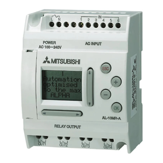
- Page 2 Programmable Controller 1. Important features of the Mitsubishi Alpha The simple, user friendly Mitsubishi α series has been designed for use around your home, office, factory... anywhere that requires flexible programmable control. Every Alpha allows you to analyse inputs and set outputs according to your program. The Alpha displays the status of your inputs and outputs on an LCD screen for quick verification.
- Page 3 Mitsubishi Alpha / Alpha2 Programmable Controller 1.1 Mitsubishi Alpha models and expansion modules Please refer to the table below for the available models of the Mitsubishi α and α2 programmable controllers: DIGITAL INPUT DIGITAL OUTPUT POWER TYPE MODEL SUPPLY Type...
- Page 4 Mitsubishi Alpha / Alpha2 Programmable Controller 2. How to Wire Your Alpha’s Power Supply, Inputs and Outputs 2.1. 100V AC - 240V AC Power Supply, Inputs and Outputs When wiring AC supplies the “Live” (Active) cable should be connected to the “L” terminal and the “Neutral”...
- Page 5 Mitsubishi Alpha / Alpha2 Programmable Controller 2.2 24V DC Power Supply, Inputs and Outputs When wiring DC supplies the “positive” cable should be connected to the "+" terminal and the negative cable should be connected to the “-” terminal. Do NOT connect the “positive” wire to the “-”...
- Page 6 Mitsubishi Alpha / Alpha2 Programmable Controller 2.3 Wiring the Output Terminals The Mitsubishi Alpha and Alpha2 controllers use relay type outputs (these can be used for switching AC or DC). Follow this diagram when wiring outputs to your Alpha. AC Power...
- Page 7 (page 53) are particularly useful. These sections describe the specific operation of each of the logic and function blocks. A program for the Mitsubishi α can contain up to 64 blocks (1500 bytes of memory). A program for the Mitsubishi α2 can contain up to 200 blocks (5000 bytes of memory).
- Page 8 Mitsubishi Alpha / Alpha2 Programmable Controller 4. How to Program your Alpha Using the Front Keypad and LCD Screen The α and α2 series programmable controllers can be programmed directly, using the front keypad. It is possible to write a large program using this method. However, the amount of the program you are able to view, while you program, is limited to the size of the LCD screen.
- Page 9 Mitsubishi Alpha / Alpha2 Programmable Controller In this section of the lesson you have learnt how to set the time and date. You’ve been introduced to the “OK”, “ESC”, UP (▲), DOWN (▼), LEFT (◄),RIGHT (►), PLUS (+) and MINUS (-) buttons. Also, you have learnt how to browse and navigate the Alpha’s menus.
- Page 10 Mitsubishi Alpha / Alpha2 Programmable Controller 4.3 How to Choose a Function Block and Connect to an Input Any function block that has an output pin can be connected to any function block that has an input pin. You will use Input 1 (In 01).
- Page 11 Mitsubishi Alpha / Alpha2 Programmable Controller 4.4 How to Set Up a Function Block Now you will set Delay to time for 5 seconds. Press RIGHT (►) The block’s labels should be flashing. Press “OK”. A menu will appear. Time Unit will be flashing. Press “OK”.
- Page 12 Mitsubishi Alpha / Alpha2 Programmable Controller 4.5 How to Connect a Function Block to an Output Press RIGHT (►) until your Delay block’s output pin is flashing. The process here is identical to what you did earlier. Connect When your delay function block’s output pin is flashing press PLUS (+) to add an output.
- Page 13 Press “OK”. Now press “OK” again to confirm the deletion. Or press “ESC” to cancel the deletion. When a function block is deleted, all connections to that function block will also be removed. Note: For more information related to the programming of the Mitsubishi α α α α and α2 α2 α2 α2...
- Page 14 Insert your Visual Logic CD. A document will appear. Notice there are links on this page to your manuals. To install Visual Logic press the button labeled Install Visual Logic Software. Once installed, the software can be run from the start menu (Start | Programs | Mitsubishi Alpha Controller | Alpha Programming).
- Page 15 Mitsubishi Alpha / Alpha2 Programmable Controller 5.2 Visual Logic Programming Environment Take this opportunity to familiarize yourself with the features of the Visual Logic’s Programming environment. Legend 1. Menu Bar 2. Standard Toolbar 3. Controller Toolbar 4. Image Toolbar 5. Drawing Toolbar 6.
- Page 16 Mitsubishi Alpha / Alpha2 Programmable Controller 5.2.1 The Function Block Diagram (FBD) Window The Function Block Diagram (FBD) window is used for programming of the α and α2 series programmable controllers. Double Click here to give your program a title...
- Page 17 Mitsubishi Alpha / Alpha2 Programmable Controller 5.2.2 The System Sketch Monitoring Window The System Sketch Monitoring window is a powerful simulation and monitoring tool. In this window you can make a drawing of your plant as it would appear in real life. Within this drawing you can draw your program’s inputs and outputs.
- Page 18 Mitsubishi Alpha / Alpha2 Programmable Controller 5.3 Visual Logic’s Modes Visual Logic can be in one of three modes: 1. Programming mode 2. Simulation mode 3. Monitor mode You will use programming mode to draw or create your program. Simulation mode to verify your program’s operation without connecting to the controller.
- Page 19 Mitsubishi Alpha / Alpha2 Programmable Controller 5.3.2 Simulation Mode The Simulation mode is a very powerful tool for debugging programs prior to writing the program to a controller. You can control the On/Off state of Inputs with the click of a mouse and you can directly set analog values.
- Page 20 6. How to Write a Simple Program using your PC and Visual Logic To create a new project, run the Visual Logic software (Start | Programs | Mitsubishi Alpha Controller | Alpha Programming), click on the “File” menu item, and select “New”. Use the “Open”...
- Page 21 Mitsubishi Alpha / Alpha2 Programmable Controller 6.1 Create a Program Remember, as a function and logic block programmer it is your task to: 1. Choose the appropriate block 2. Set the block’s parameters (where this is necessary) 3. Connect your blocks in the correct sequence for your application You will use these steps to create a program to do the following: •...
- Page 22 Mitsubishi Alpha / Alpha2 Programmable Controller Your program should look like this. There is no need to set any block’s parameters here, so you can move on to connecting your blocks in the correct sequence. For this task use the Wiring Tool in the bottom left hand corner of your screen.
- Page 23 Mitsubishi Alpha / Alpha2 Programmable Controller 6.2 Simulate your program Now you can switch to simulation mode to verify your program operates as specified. Click this button to switch to Simulation mode Double-click the buttons to simulate a momentary switch 6.3 Configure your COM port...
- Page 24 Mitsubishi Alpha / Alpha2 Programmable Controller 6.4 Download and Monitor your program Apply power to your controller. Please refer to section 2 of this document. Ensure the Controller is stopped by clicking Controller|Drive Controller|Stop. Click Controller|Write to Controller This dialog box will appear: Ensure these check boxes look like this, then press OK.
- Page 25 6.7 Read a Program from the Controller to your PC You can read an existing program from the controller. To read the current program from the Mitsubishi α or α2 controller, click Controller|Read from Controller. You will see this dialog box.
- Page 26 Mitsubishi Alpha / Alpha2 Programmable Controller 7. How to write a more complex program using your PC and Visual Logic In this section you will extend the program you’ve just written. You will add a timer to automatically switch off the contactor after 10 seconds.
- Page 27 Mitsubishi Alpha / Alpha2 Programmable Controller This dialog box will appear: Double click in here, then type “10” Click this radio button to set the time unit to 1 second Now Click “OK”. You have created a 10 second ON-delay. The output of the delay block will come ON after 10 seconds has expired.
- Page 28 Mitsubishi Alpha / Alpha2 Programmable Controller Use the wiring tool to make the following connections. Remember, to delete a connection simply click the connection then press Delete on your keyboard. You can move the connections to tidy your program, simply click on the connection then position your cursor over the connection.
- Page 29 Programmable Controller 8. An Example Program for Manual/Automatic Ventilation Fan The following is an example for a ventilation fan controller, using a Mitsubishi Alpha2 programmable controller. The program will have two modes. Manual mode - will cause the fan to start when the “START” push-button (connected on the Input 01) is momentary pressed, and continue to run until the “STOP”...
- Page 30 Mitsubishi Alpha / Alpha2 Programmable Controller 15. Click on the “LOGI” symbol into the “Accessories” Toolbar to display the function blocks for this group. Search for the “AND” function block, and click on it 16. Paste it on the FBD, next to the Input 03 (B03) 17.
- Page 31 Mitsubishi Alpha / Alpha2 Programmable Controller 23. From the “LOGI” group in the “Accessories” Toolbar search for the “OR” function block, and click on it 24. Paste the “OR” function block (B05) on the FBD, below the “SET RESET” function block (B01) 25.
- Page 32 Mitsubishi Alpha / Alpha2 Programmable Controller 43. Connect the output point of the “SET RESET” function block (B09) to the second input of the “OR” function block (B02) 44. Connect the output point of the “SET RESET” function block (B09) to the input of the “DELAY”...
- Page 33 Mitsubishi Alpha / Alpha2 Programmable Controller 9. An Example Program for Time Switched Lighting This program is an example. It is for demonstration purposes only. This program will switch on lighting at a pre-specified time and day. 1. Choose these blocks from the “Accessories” Toolbar 2.
- Page 34 Mitsubishi Alpha / Alpha2 Programmable Controller Now you are ready to set the blocks parameters. The Day lighting operates each and every weekday. It will turn on at 8:00am then turn off at 16:30. Double click the Time Switch Block. This dialog box will appear:...
- Page 35 Mitsubishi Alpha / Alpha2 Programmable Controller Now create another to switch to OFF at 16:30pm 2. Every week 3. Every weekday 1. Switch OFF 4. At 16:30 5. OK...
- Page 36 Mitsubishi Alpha / Alpha2 Programmable Controller Press OK This is how simple it is configure a Time Switch Block. Follow a similar procedure to configure the Time Switches for the Weekend and Car Park lighting. Weekend lighting:...
- Page 37 Mitsubishi Alpha / Alpha2 Programmable Controller Car Park lighting: To set the time on your Alpha: Click: Option|Change Current Time To set the time your Alpha must be connected to your PC. See section 6.3. Set the time and date in this dialog box then Click: Write To Controller.
- Page 38 Mitsubishi Alpha / Alpha2 Programmable Controller 10. Converting Ladder Logic to Alpha Logic and Function Blocks Contents: 1. Positive logic 2. Negative logic (NOT) 3. AND 4. OR 5. NAND 6. NOR 7. XOR 8. On delay timer 9. One shot timer 10.
- Page 39 Mitsubishi Alpha / Alpha2 Programmable Controller 3. AND 4. OR...
- Page 40 Mitsubishi Alpha / Alpha2 Programmable Controller 5. NAND Inverted Coil 6. NOR Inverted Coil...
- Page 41 Mitsubishi Alpha / Alpha2 Programmable Controller 7. XOR 8. On Delay Timer 9. One Shot Timer...
- Page 42 Mitsubishi Alpha / Alpha2 Programmable Controller 10. Flicker 11. Set Reset 12. Comparison...
- Page 43 Mitsubishi Alpha / Alpha2 Programmable Controller 13. Arithmetic...