Crown CTs 4200 Operation Manual
Crown cts multi-channel series operation manual
Hide thumbs
Also See for CTs 4200:
- Operation manual (44 pages) ,
- Specifications (2 pages) ,
- Architectural & engineering specifications (1 page)
Table of Contents
Advertisement
Operation Manual
Obtaining Other Language Versions: To obtain information in another language about the use of this product, please contact your
local Crown Distributor. If you need assistance locating your local distributor, please contact Crown at 574-294-8000.
This manual does not include all of the details of design, production, or variations of the equipment. Nor does it cover every possible
situation which may arise during installation, operation or maintenance.
The information provided in this manual was deemed accurate as of the publication date. However, updates to this information may have
occurred. To obtain the latest version of this manual, please visit the Crown website at www.crownaudio.com.
Trademark Notice: Crown, Crown Audio, Amcron, Com-Tech, IQ System, and Multi-Mode are registered trademarks of Crown Inter-
national. Other trademarks are the property of their respective owners.
©2005 by Crown Audio
CTs Multi-Channel Series
Some models may be exported under the name Amcron.
®
Inc., 1718 W. Mishawaka Rd., Elkhart, Indiana 46517-9439 U.S.A. Telephone: 574-294-8000
CTs 4200
CTs 8200
®
134434-7A
3/05
Advertisement
Table of Contents

Related Manuals for Crown CTs 4200


Summary of Contents for Crown CTs 4200
- Page 1 To obtain the latest version of this manual, please visit the Crown website at www.crownaudio.com. Trademark Notice: Crown, Crown Audio, Amcron, Com-Tech, IQ System, and Multi-Mode are registered trademarks of Crown Inter- national. Other trademarks are the property of their respective owners.
-
Page 2: Important Safety Instructions
Important Safety Instructions Read these instructions. Keep these instructions. Heed all warnings. Follow all instructions. Do not use this apparatus near water. Clean only with a dry cloth. Do not block any ventilation openings. Install in accordance with the manufacturer’s instruc- tions. -
Page 3: Declaration Of Conformity
CTs Multi-Channel Power Amplifiers Crown International, Inc. ISSUED BY: Crown International, Inc. 1718 W. Mishawaka Road Elkhart, Indiana 46517 U.S.A. European Representative's Name and Address: Nick Owen 35, Bassets Field Thornhill Cardiff. South Glamorgen CF14 9UG United Kingdom Equipment Type: Commercial Audio Power Amplifiers Family Name: CTs Model Names: CTs 4200A, CTs 8200A EMC Standards:... -
Page 4: Table Of Contents
Important Safety Instructions ...2 Declaration of Conformity ...3 1 Welcome ... 5 1.1 Features ...5 2 How to Use This Manual ... 5 3 Setup ... 6 3.1 Unpack Your Amplifier ...6 3.2 Install Your Amplifier ...6 3.3 Ensure Proper Cooling ...6 3.4 Choose Input Wire and Connectors ...7 3.5 Choose Output Wire and Connectors ...7 3.6 Wire Your System ...8... -
Page 5: Welcome
CTs Multi-Channel Power Amplifiers CTs 4200 Maximum Average Power Dual in watts with 0.1% THD. 4 Channels Driven 1 kHz 20 Hz–20 kHz 4-ohm (per ch.) 260W 215W 8-ohm (per ch.) 180W 190W 70V (per ch.) 220W 220W 1 Channel Driven 1 kHz 20 Hz–20 kHz... -
Page 6: Setup
Signal Ready Data Bridge Bridge Figure 3.1 Dimensions Left: CTs 4200 page 6 3.2 Install Your Amplifier CAUTION: Before you begin, make sure your amplifier is disconnected from the power source, with the power switch in the “off” position and all level controls turned completely down (counterclock- wise). -
Page 7: Choose Input Wire And Connectors
CAUTION: Never connect the speaker return to the chassis of the amplifier, or damage to the amplifier may result. CAUTION: Never use shielded cable for output wiring. Operation Manual NOTE: CTs 8200 is shown. Some CTs 4200 features are in different locations. Wire Size 16 AWG 14 AWG... -
Page 8: Wire Your System
INPUTS: Connect input wiring for each channel. OUTPUTS: Maintain proper polarity (+/–) on output connectors. Connect Channel 1 positive (+) speaker load to Channel 1 positive terminal of amp; repeat for negative (–). Repeat each channel wiring as for Channel 1. Refer to Section 3.5 for output con- nector pin assignments. -
Page 9: Bridge-Mono 16/8 Mode
“Bridge 16/8” position. INPUTS: Connect input wiring only to the lower- (odd-) numbered channel pair. OUTPUTS: Connect the speaker across the posi- tive terminals of each channel pair. Do not use the negative terminals of the channel pair when the pair is being operated in Bridge-Mono mode. -
Page 10: Connect To Ac Mains
3 Setup 3.7 Connect to AC Mains Connect your amplifier to the AC mains power source (power outlet) with the supplied AC power cordset. First, connect the IEC end of the cordset to the IEC connector on the amplifier; then, plug the other end of the cordset to the AC mains. -
Page 11: Operation
1 channel. Due to the amplifier’s output protection, such a config- uration may result in premature clipping, speaker damage or a blown power fuse. Remember: Crown is not liable for damage that results from overdriving other system compo- nents. -
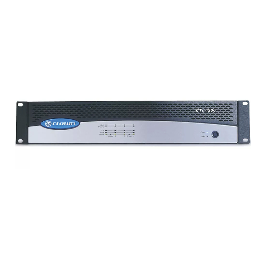
Page 12: Front Panel Controls And Indicators
4 Operation 4.2 Front Panel Controls and Indicators Note: CTs 8200 is shown. Some CTs 4200 features are in different locations. A. Bridge Mode Indicator Yellow LED, one per channel pair, illumi- nates when the channel pair's Mode Switch is set to the “Bridge” position. If Mode switch is changed while amplifier is powered up, Bridge LED will flash, indicat- ing that the amplifier must be powered off... -
Page 13: Back Panel Controls And Connectors
Operation Manual M. Accessory Panel CTs 4200: Accepts an optional IQ-MC4A or VCA-MC4A module. CTs 8200: Accepts an optional IQ-MC8 or VCA-MC8 module (explained in Section 5.3.1, Control Modules). -
Page 14: Advanced Features And Options
If a CTs multi-channel amp is powering multiple zones, and a channel fails, the other zones continue to operate. FIT makes the CTs 4200 and CTs 8200 the most trustworthy multi-channel amplifiers in the business! page 14 5.1.4 35-Hz High-Pass Filter... -
Page 15: Channel Level Control
CTs Multi-Channel Power Amplifiers 5 Advanced Features and Options 5.2.4 Channel Level Control The signal level for each input can be attenu- ated accurately by adjusting the 21-step Level Control (see Section 4.2). Figure 5.2 shows the amount of attenuation in dB for each detent. Note: Attenuation per detent varies with operat- ing mode since gain varies with operating mode. -
Page 16: Options
4-VCAP: Two-gang wall-mount panel with four VCA channel volume controls (for any CTs model) 5.3.2 Input Sensitivity The CTs 4200 and CTs 8200 have a fixed input sen- sitivity of 1.4V. A service option is available for other input sensitivities. CTs Multi-Channel Power Amplifiers... -
Page 17: Troubleshooting
CTs Multi-Channel Power Amplifiers 6 Troubleshooting Operation Manual CONDITION: Power indicator is off. POSSIBLE REASON • The amplifier has lost AC power. • The amplifier’s Power switch is off. • The amplifier is not plugged into the power receptacle. • The amplifier output level is so high that the power supply fuse has blown. - Page 18 Signal indicator is flashing. • Speakers not connected. • Open circuit due to speaker failure. • There is a short on the amplifier output. First disconnect your speakers from the affected channel(s) one by one to determine if one of the loads is shorted.
-
Page 19: Specifications
16 Ohm 100V (50 Ohm) at 0.1% THD * Constant Voltage full bandwidth power ratings support 100 Hz - 20 kHz due to automatic high-pass filters. Operation Manual CTs 4200: MINIMUM GUARANTEED POWER Dual Mode Channels Driven 1 kHz 4 Ohm 8 Ohm 70V (25 Ohm) at 0.1% THD... - Page 20 Power Draw at Idle (120VAC mains, all channels in 4/8 ohm mode) Power Draw at Idle (120VAC mains, all channels in 70V mode) Cooling Dimensions: Width, Height, Depth Net Weight, Shipping Weight page 20 CTs 4200 ± 0.5 dB ± 35° 100 dB unweighted < 0.05% < 0.05% >180...
- Page 21 CTs Multi-Channel Power Amplifiers 7 Specifications Figure 7.3 CTs 8200 Typical Frequency Response (1 W) Figure 7.4 CTs 8200 Typical Phase Response (1 W) Figure 7.5 CTs 8200 Typical Damping Factor vs. Frequency Operation Manual page 21...
- Page 22 CTs Multi-Channel Power Amplifiers 7 Specifications Figure 7.6 CTs 8200 Typical Output Impedance vs. Frequency Figure 7.7 CTs 8200 Typical Crosstalk vs. Frequency page 22 Operation Manual...
-
Page 23: Ac Power Draw And Thermal Dissipation
1/3rd Power Pink Noise 8 Ohms/Ch. 16 Ohms Bridge Typical of program material 4 Ohms/Ch. with severe clipping. 8 Ohms Bridge 70V/Ch. 100V Bridge Operation Manual CTs 4200 Rated Line Current Line Current Power 120VAC 230VAC watts in 200x4 400x2... - Page 24 8 AC Power Draw and Thermal Dissipation AC Power Draw and Thermal Dissipation: Pink noise 12dB crest factor, bandwidth limited 22Hz to 22kHz. Typical line impedance used. Measurements made with 120VAC mains. Line current figures for 230VAC units derived by multiplying 120VAC figures by 0.5. Data based on all channels driven.
-
Page 25: Service
9.2.5 Estimate Approval Approval of estimate must be given within 90 days after being notified by Crown Audio Inc. Units still in the pos- session of Crown after 90 days of the estimate will become the property of Crown Audio Inc. -
Page 26: Warranty
10 Warranty SUMMARY OF WARRANTY Crown International, 1718 West Mishawaka Road, Elkhart, Indiana 46517-4095 U.S.A. warrants to you, the ORIGINAL PURCHASER and ANY SUB- SEQUENT OWNER of each NEW Crown product, for a period of three (3) years from the date of purchase by the original purchaser (the “warranty period”) that the new Crown product is free of defects in materials and workmanship. - Page 27 CTs Multi-Channel Power Amplifiers 10 Warranty SUMMARY OF WARRANTY Crown International, 1718 West Mishawaka Road, Elkhart, Indiana 46517-4095 U.S.A. warrants to you, the ORIGINAL PURCHASER and ANY SUB- SEQUENT OWNER of each NEW Crown1 product, for a period of three (3) years from the date of pur- chase by the original purchaser (the “warranty period”) that the new Crown product is free of defects in materials and workmanship, and we...
- Page 28 CTs Multi-Channel Power Amplifiers NOTES page 28 Operation Manual...
- Page 29 CTs Multi-Channel Power Amplifiers Shipping Address: Crown Audio Factory Service, 1718 W. Mishawaka Rd., Elkhart, IN 46517 SRA #: __________________(If sending product to Crown factory service.) Individual or Business Name: ____________________________________________________________________________________________________________________________________________________________ Phone #: __________________________________________________ Street Address (please, no P.O. Boxes): _____________________________________________________________________________________________________________________________________________________...
- Page 30 CTs Multi-Channel Power Amplifiers THIS PAGE INTENTIONALLY LEFT BLANK page 30 Operation Manual...
- Page 31 CTs Multi-Channel Power Amplifiers THIS PAGE INTENTIONALLY LEFT BLANK Operation Manual page 31...