Crown CTS4200 Operation Manual
Cts multi-channel usp/cn series
Hide thumbs
Also See for CTS4200:
- Operation manual (32 pages) ,
- Specifications (2 pages) ,
- Architectural & engineering specifications (1 page)
Table of Contents
Advertisement
Quick Links
CTs Multi-Channel USP/CN Series
Operation Manual
Obtaining Other Language Versions: To obtain information in another language about the use of this product, please contact your
local Crown Distributor. If you need assistance locating your local distributor, please contact Crown at 574-294-8000.
This manual does not include all of the details of design, production, or variations of the equipment. Nor does it cover every possible
situation which may arise during installation, operation or maintenance.
The information provided in this manual was deemed accurate as of the publication date. However, updates to this information may have
occurred. To obtain the latest version of this manual, please visit the Crown website at www.crownaudio.com.
Trademark Notice: Crown, Crown Audio, Amcron, Com-Tech, IQ System, and Multi-Mode are registered trademarks of Crown
Inter national. HiQnet and System Architect are trademarks of Harman Pro Group. Other trademarks are the property of their respective
own ers.
©2008 by Crown Audio
Some models may be exported under the name Amcron.
®
Inc., 1718 W. Mishawaka Rd., Elkhart, Indiana 46517-9439 U.S.A. Telephone: 574-294-8000
CTs 4200USP/CN
CTs 8200USP/CN
®
139309-3B
8/08
Advertisement
Table of Contents

Related Manuals for Crown CTS4200


Summary of Contents for Crown CTS4200
-
Page 1: Operation Manual
Obtaining Other Language Versions: To obtain information in another language about the use of this product, please contact your local Crown Distributor. If you need assistance locating your local distributor, please contact Crown at 574-294-8000. This manual does not include all of the details of design, production, or variations of the equipment. Nor does it cover every possible situation which may arise during installation, operation or maintenance. -
Page 2: Important Safety Instructions
Important Safety Instructions Important Safety Instructions Importantes Instructions de Sécurité Importantes Instructions de Sécurité Read these instructions. Read these instructions. Keep these instructions. Keep these instructions. Heed all warnings. Heed all warnings. Follow all instructions. Follow all instructions. Do not use this apparatus near water. Do not use this apparatus near water. -
Page 3: Declaration Of Conformity
CTs Multi-Channel Power Amplifi ers Crown International, Inc. Issued By: Crown International, Inc. 1718 W. Mishawaka Road European Representative’s Name and Address: David J. Budge 10 Harvest Close Yateley GU46 6YS United Kingdom Equipment Type: Commercial Audio Power Amplifi ers... -
Page 4: Table Of Contents
9.2.3 Factory Service Shipping Instructions ... 36 9.2.4 Packing Instructions ... 36 9.2.5 Estimate Approval ... 36 9.2.6 Payment of Non-Warranty Repairs... 36 10 Warranty ... 37 Product Registration ... 41 Crown Factory Service Information Form ... 43 Operation Manual... -
Page 5: Welcome
225W Building on the foundation of the Com-Tech 8-ohm (per ch.) 220W 210W Crown’s CTs Series offers new fl exibility and value for 70V (per ch.) 250W 245W installed sound applications. The Com-Tech Series were the fi rst to offer independent selection of high- and low- Bridge-Mono impedance operation for a specifi... -
Page 6: Setup
If damage is found, notify the transpor tation company immediately. Only you can ini tiate a claim for shipping damage. Crown will be happy to help as needed. Save the shipping carton as evidence of damage for the shipper’s inspection. -
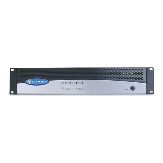
Page 7: Front Panel Controls And Indicators
CTs Multi-Channel Power Amplifi ers 2 Setup (continued) 2.4 Front Panel Controls and Indicators Note: CTs 8200USP/CN is shown. Some CTs 4200 USP/CN features are in different locations. A. Bridge Mode Indicator Yellow LED, one per channel pair, illuminates when the channel pair’s Mode Switch is set to the “Bridge”... -
Page 8: Back Panel Controls And Connectors
Note: CTs 8200USP/CN is shown. Some CTs 4200USP/CN features are in different loca tions. K. AC Power Cord Connector Standard IEC type 320 inlet. 120V models: 15-amp. 220-240V models: 10-amp. Voltage is indicated above IEC inlet. L. Output Connectors One four-pole terminal strip for every two chan nels with touch-proof cover. -
Page 9: Cobranet And Control Module
See Section 3.2.1. The dual RJ45 CobraNet connectors allow a Primary & Secondary connection to the 100 Mbps Ethernet network. Should the Primary connection lose link activity with the net work, the module will automatically switch to the Secondary connection to ensure uninterrupted audio and control. -
Page 10: Choose Input Wire And Connectors
When possible, use balanced wiring for signal input, which provides better rejection of unwanted noise and hum. For more information, refer to the Crown Amplifi er Application Guide, available online at www.crownaudio.com NOTE: Custom wiring should only be performed by qualifi ed per sonnel. -
Page 11: Audio Wiring
CH 1 CH 4 CH 3 DUAL DUAL BRIDGE Figure 2.10 System Wiring and Control Settings, Dual Mode, 70V See the Crown Amplifi er Appli cation Guide, available online at www.crownaudio.com, for pin assignments for Output panel shown with touch-proof cover plate removed. -
Page 12: Bridge-Mono 16/8 Mode
Figure 2.11 System Wiring and Control Settings, Bridge-Mono Mode, 16/8 Ohm. 100V BRIDGE DUAL DUAL CH 2 CH 1 CH 4 CH 3 DUAL DUAL BRIDGE Figure 2.12 System Wiring and Control Settings, Bridge-Mono Mode, 100V See the Crown Amplifi er Appli cation Guide, Operation Manual... -
Page 13: Network Wiring Rules
Operation Manual Crown strongly recommends the use of a 100 Mb confi gurations. Also, the amplifi er must be run within the Ether net network for control and monitoring. -
Page 14: Operation
1 channel. Due to the amplifi er’s output protection, such a confi g uration may result in premature clipping, speaker damage or a blown power fuse. Remember: Crown is not liable for damage that results from overdriving other system compo nents. Operation Manual... -
Page 15: Cobranet And Control Module Features
Make connections with a standard CAT5 cable to a network switch port. Crown strongly recommends the use of switches and not hubs in the network. Hubs will limit the amount of CobraNet traffi c and create unnecessary limitations in the network. - Page 16 3 Operation (continued) 2. Hold the Reset/Preset switch in for two fl ashes of the Data light (longer than 2 seconds). 3. The Data indicator will fl ash rapidly for a moment. 4. Restore the audio input signals. To restore the unit including presets to factory default settings: 1.
- Page 17 CTs Multi-Channel Power Amplifi ers 3 Operation (continued) 3.2.23 Input Signal Compressor/Limiter An input signal compressor/limiter is available for each channel. Five parameters control this feature: Enable: Enables or disables this function. Threshold: Sets the level, in dBu, above which the compressor begins to attenuate the input signal.
- Page 18 3 Operation (continued) Most amplifi er/load systems can be confi gured and supervised by following these steps: 1. Confi gure your audio system using a known “good” load, then enable the Load Supervision feature. 2. Provide typical program material at a level high enough to light the “test”...
- Page 19 CTs Multi-Channel Power Amplifi ers 3 Operation (continued) CobraNet Audio: Assign this in the CobraNet Input section of the software. See Section 3.3.2 for more details. Choices for the CobraNet Input are from any of four bundles, and any of the eight channels available.
- Page 20 3 Operation (continued) 3.3.3 CobraNet Output Routing CobraNet output routing includes the following controls: CobraNet Transmit Bundles The amplifi er can transmit up to four unique CobraNet Bundles (TxA, TxB, TxC, TxD). Each Transmit Bundle includes the follow ing controls and monitor functions: •...
-
Page 21: Advanced Features
The AUX output has two enhanced modes: Error Reporting and Flash Preset. In Error Reporting mode, the AUX port can be set up to change state when any selected error (clip, thermal, amp fault, load impedance, and AC line level) is detected. With this feature, the AUX output of each amplifi... -
Page 22: Protection Systems
If an amplifi er channel requires service, the correspond- ing Fault indicator will illuminate to alert the user of this condition. If this occurs, return the amplifi er to the Crown factory or to an authorized Crown service center. 4.2.3 Fault Isolation Topology (FIT) Crown’s new FIT (Fault Isolation Topology) design... -
Page 23: Channel Level Control
CTs Multi-Channel Power Amplifi ers 4 Advanced Features (continued) 4.2.12 Channel Level Control The signal level for each input can be attenu ated accurately by adjusting the 21-step Level Control (see Section 2.5). Figure 4.5 shows the amount of attenuation in dB for each detent. Note: Attenuation per detent varies with operat ing mode since gain varies with operating mode. -
Page 24: Troubleshooting
The amplifi er output level is so high that the power supply fuse has blown. Verify that input levels and output impedances are within safe ranges. Refer the unit to an authorized Crown service center for fuse replacement. CONDITION: Power indicator is fl ashing. - Page 25 5 Troubleshooting (continued) Operation Manual CONDITION: No sound, even though the amp has power. Power LED is on without fl ashing and the amp is receiving an input signal. Signal indicator is fl ashing. • Speakers not connected. • Open circuit due to speaker failure.
- Page 26 5 Troubleshooting (continued) NOTE: Actual product artwork may vary slightly. Problem: Data indicator is not fl ashing, even though a valid com mand was sent. Possible causes: • Command was not addressed to the USP/CN. • Network cable is disconnected or broken. To assist with troubleshooting, System Architect can set an option for force the data indicator on.
-
Page 27: Specifi Cations
CTs Multi-Channel Power Amplifi ers 6 Specifi cations Performance Frequency Response (at 1 watt, 20 Hz - 20 kHz) Phase Response (at 1 watt, 10 Hz - 20 kHz) Signal to Noise Ratio below rated power (20 Hz to 20 kHz) Total Harmonic Distortion (THD) at 1 watt, from 20 Hz to 20 kHz Intermodulation Distortion (IMD) 60 Hz and 7 kHz at 4:1, from 163 milliwatts to full bandwidth power, typical... - Page 28 CTs Multi-Channel Power Amplifi ers 6 Specifi cations (continued) Figure 6.2 CTs 8200USP/CN Typical Phase Response (1 W) Figure 6.1 CTs 8200USP/CN Typical Frequency Response (1 W) Figure 6.3 CTs 8200USP/CN Typical Damping Factor vs. Frequency page 28 Operation Manual...
- Page 29 CTs Multi-Channel Power Amplifi ers 6 Specifi cations (continued) Figure 6.4 CTs 8200USP/CN Typical Output Impedance vs. Frequency Figure 6.5 CTs 8200USP/CN Typical Crosstalk vs. Frequency Operation Manual page 29...
- Page 30 6 Specifi cations (contin- CTs 4200USP/CN: MINIMUM GUARANTEED POWER Dual Mode Channels Driven 4 Ohm 8 Ohm Figure 6.1 CTs 70V (25 Ohm) at 0.1% THD 4200USP/CN Bridge-Mono Mode Typical Fre quency Channel Pairs Driven Response (1 W) 8 Ohm 16 Ohm 100V (50 Ohm) * Constant Voltage full bandwidth power ratings support 100 Hz - 20 kHz due to automatic high-pass filters.
-
Page 31: Ac Power Draw And Thermal Dissipation
CTs Multi-Channel Power Amplifi ers 7 AC Power Draw and Thermal Dissipation AC Power Draw and Thermal Dissipation: Pink noise 12dB crest factor, bandwidth limited 22Hz to 22kHz. Typical line impedance used. Measurements made with 120VAC mains. Line current figures for 230VAC units derived by multiplying 120VAC figures by 0.5. Data based on all channels driven. - Page 32 7 AC Power Draw and Thermal Dissipation (continued) AC Power Draw and Thermal Dissipation: Pink noise 12dB crest factor, bandwidth limited 22Hz to 22kHz. Typical line impedance used. Measurements made with 120VAC mains. Line current figures for 230VAC units derived by multiplying 120VAC figures by 0.5. Data based on all channels driven.
-
Page 33: Network And Cobranet Basics
8 Network and CobraNet Basics This section provides additional information about HiQnet or Network basics. For more information about any of these topics, contact Crown Technical Support. For AUX connector wiring, see Sections 3.2.7 and 4.1. 8.1 Network Basics HiQnet is a network-based protocol that can control and monitor networked components over a common TCP/IP network. -
Page 34: A Closer Look At Cobranet
8 Network and CobraNet Basics (continued) Each component has three identifi ers that are used in the HiQnet system: • Media Access Control (MAC) Address • Internet Protocol (IP) Address • HiQnet Address Let’s explain each identifi er. Media Access Control (MAC) Address: This is a physical address that specifi... -
Page 35: Audio Specs
In System Architect, you create audio connections between sending devices (transmitters) and receiving devices (receivers). For example, a mixer could be a transmitter, and a power amp could be a receiver. You assign each connection a Bundle number. The Bundle number indicates which devices are communicating with each other. -
Page 36: Service
Complete the Crown Audio Factory Service Information For more information, please contact us direct. form, in the back of this manual, when returning a Crown product to the factory or authorized service center. The form A Service Return Authorization (SRA) is required for must be included with your product inside the box or in a product being sent to the factory for repair. -
Page 37: Warranty
ITEMS EXCLUDED FROM THIS CROWN WARRANTY This Crown Warranty is in effect only for failure of a new Crown product which occurred within the Warranty Period. It does not cover any product which has been damaged because of any... - Page 38 “Crown” in this warranty. ITEMS EXCLUDED FROM THIS CROWN- WARRANTY This Crown Warranty is in effect only for failure of a new Crown product which occurred within the Warranty Period. It does not cover any product which has been damaged because of any...
- Page 39 CTs Multi-Channel Power Amplifi ers THIS PAGE INTENTIONALLY LEFT BLANK Operation Manual page 39...
- Page 40 CTs Multi-Channel Power Amplifi ers THIS PAGE INTENTIONALLY LEFT BLANK page 40 Operation Manual...
-
Page 41: Product Registration
________________________________ Product purchased from: *(Business/Individual) ___________________________ Country: ________________________ Comments: ____________________________________________________________________________________ _____________________________________________________________________________________________ _____________________________________________________________________________________________ Operation Manual PRODUCT REGISTRATION Crown Audio, Inc. Fax: 574-294-8329 1718 W Mishawaka Rd Elkhart IN 46517 OWNER’S INFORMATION - PLEASE PRINT PRODUCT INFORMATION * SERIAL # e.g. 8000000000... - Page 42 CTs Multi-Channel Power Amplifi ers THIS PAGE INTENTIONALLY LEFT BLANK page 42 Operation Manual...
-
Page 43: Crown Factory Service Information Form
CTs Multi-Channel Power Amplifi ers Crown Audio Factory Service Information Shipping Address: Crown Audio Factory Service, 1718 W. Mishawaka Rd., Elkhart, IN 46517 SRA #: __________________(If sending product to Crown factory service.) Individual or Business Name: ______________________________________________________________________________________________________________________________________________________ _____________________ Phone #: __________________________________________________ ______ Street Address (please, no P.O.