Table of Contents
Advertisement
Quick Links
Installation, Operation, and Maintenance
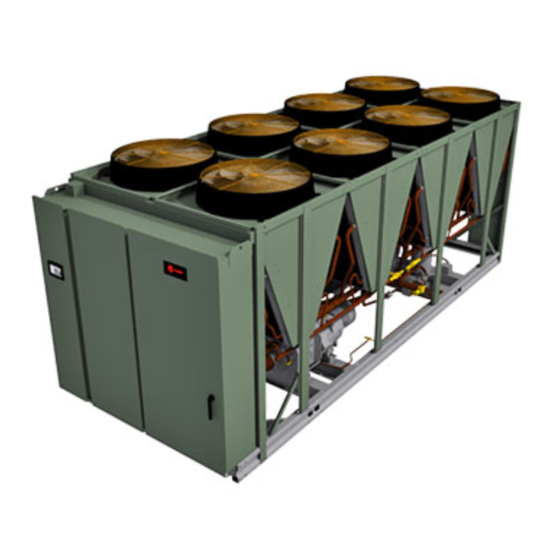
Ascend™ Air-Cooled Chiller
Model ACR Series C
150 to 550 Nominal Tons
Only qualified personnel should install and service the equipment. The installation, starting up, and servicing of heating, ventilating, and air-conditioning equipment
can be hazardous and requires specific knowledge and training. Improperly installed, adjusted or altered equipment by an unqualified person could result in death or
serious injury. When working on the equipment, observe all precautions in the literature and on the tags, stickers, and labels that are attached to the equipment.
December 2023
SAFETY WARNING
AC-SVX003A-EN
573253740001
Advertisement
Table of Contents

Related Manuals for Trane Ascend ACR C Series


Summary of Contents for Trane Ascend ACR C Series
- Page 1 Installation, Operation, and Maintenance Ascend™ Air-Cooled Chiller Model ACR Series C 150 to 550 Nominal Tons 573253740001 SAFETY WARNING Only qualified personnel should install and service the equipment. The installation, starting up, and servicing of heating, ventilating, and air-conditioning equipment can be hazardous and requires specific knowledge and training.
- Page 2 (HCFCs). Not all refrigerants containing these compounds bump cap, fall protection, electrical PPE and arc have the same potential impact to the environment. Trane flash clothing). ALWAYS refer to appropriate advocates the responsible handling of all refrigerants.
- Page 3 This document and the information in it are the property of Environmental, Health and Safety (EHS) policies Trane, and may not be used or reproduced in whole or in when performing work such as hot work, part without written permission. Trane reserves the right to...
-
Page 4: Table Of Contents
Table of Contents Model Number Information ....7 Refrigerant Pressure Relief Valves ..52 Nameplates. - Page 5 Full Load to Minimum Load ... . . 88 Trane Service ......120...
- Page 6 Table of Contents Operator Log......122 AC-SVX003A-EN...
-
Page 7: Model Number Information
Model Number Information Nameplates Model Number Coding System Model numbers are composed of numbers and letters that Unit nameplates are applied to the exterior of the control represent features of the equipment. panel. A compressor nameplate is located on each compressor. -
Page 8: Model Number Descriptions
B = High Short Circuit Amp Rating N = Factory Insulation — All Cold Parts 0.75” Digit 32 — Electrical Accessories U = Trane Commercial Systems, H = Evaporator-only Insulation for High Humidity/ Pueblo, CO USA Low Evap Temp 1.25”... - Page 9 Model Number Descriptions Digit 33 — Remote Communication Option Digit 42 — Free-Cooling X = None X = None L = LonTalk® Interface T = Total Direct Free-Cooling B = BACnet® TP Interface J = Total Direct Free Cooling + 1V Free-Cooling Coils M = Modbus®...
-
Page 10: Compressor Information
Model Number Descriptions Compressor Information CHHS MODEL NUMBER (GP4) CHHW MODEL NUMBER (GP2, GP2.5) SERIAL NUMBER Digit 1, 2, 3, 4 — Compressor Type Digit 1, 2, 3, 4 — Compressor Family Digit 1, 2 — Year CHHS = Positive displacement, helical rotary (twin CHHW = Positive displacement, helical rotary. -
Page 11: General Information
General Information Unit Length plugs, electrical diagrams, and service literature, which are placed inside the control panel for shipment. For unit sizes 330 tons and smaller, units are EXTENDED Optional elastomeric isolators (model number digit 38 = 1) length if either of the following are selected: are shipped in the following locations: •... - Page 12 General Information Table 1. General data - 150 to 330 ton units (continued) Unit Size (tons) Coil Length 1987 Coil Height 1252 Fins/Ft Ambient Temperature Range Standard Ambient °F (°C) 32 to 105 (0 to 40.6) Low Ambient °F (°C) 0 to 105 (-17.7 to 40.6) Extreme Low Ambient °F (°C) -20 to 105 (-28.9 to 40.6)
- Page 13 General Information Table 2. General data - 375 to 550 ton units (continued) Unit Size (tons) °F Max. Water Temperature °C 48.9 48.9 48.9 48.9 48.9 48.9 psig Min. Water Pressure psig Max. Water Pressure 1034.2 1034.2 1034.2 1034.2 1034.2 1034.2 1 Pass Arrangement Evap Water Connection Size...
- Page 14 General Information Table 2. General data - 375 to 550 ton units (continued) Unit Size (tons) Oil Charge/ckt 18.2 13.2 18.2 13.2 18.2 13.2 18.2 13.2 18.2 18.2 18.2 18.2 Relief Valves High Side Relief setting psig Rated Capacity lba/min 29.5 Quanity per unit Factory connection...
- Page 15 General Information AC-SVX003A-EN...
-
Page 16: Pre-Installation
Take photos of the damage, if possible. refrigerant charge is intact. If it is not, contact a • The owner must provide reasonable evidence that the qualified service organization and the appropriate damage did not occur after delivery. Trane sales office. AC-SVX003A-EN... -
Page 17: Installation Requirements
• Meet foundation requirements Foundation • Safety chains • Clevis connectors Rigging • Lifting beam • Spreader bar Trane, or an agent of Trane specifically authorized to perform Disassembly/Reassembly start-up of Trane® products (as required) (contact your local Trane office for pricing) Elastomeric isolators •... -
Page 18: Dimensions And Weights
Dimensions and Weights Weights Table 4. Weights — 150 to 330 ton units Standard Length Extended Length Unit Free Condenser Pump Option Size Cooling Shipping Operating Shipping Operating Length (tons) Option 12000 5450 12200 5540 14200 6450 14400 6540 12100 5490 12200 5540... - Page 19 Dimensions and Weights Table 4. Weights — 150 to 330 ton units (continued) Standard Length Extended Length Unit Free Condenser Pump Option Size Cooling Shipping Operating Shipping Operating Length (tons) Option 17500 7940 17700 8030 19600 8900 19900 9030 TDFC 21800 9890 23900...
-
Page 20: Service Clearance
Dimensions and Weights Service Clearance Figure 1. Unit service clearance requirements — 150 to 330 ton units NO OBSTRUCTIONS ABOVE UNIT Control Panel 85” (2160mm) See note 3 40” (1016 24” (600.1mm) note 1 36” (914.4mm) TOP VIEW Figure 2. Unit service clearance requirements — 375 to 550 ton units Control Panel 85”... -
Page 21: Unit Dimensions
Dimensions and Weights Unit Dimensions Unit Sizes 150 to 330 Tons Figure 3. Dimensions — 150 to 330 ton units, standard length AC-SVX003A-EN... - Page 22 Dimensions and Weights Figure 4. Dimensions — 150 to 330 ton units, standard length, mounting and lifting AC-SVX003A-EN...
- Page 23 Dimensions and Weights AC-SVX003A-EN...
- Page 24 Dimensions and Weights AC-SVX003A-EN...
- Page 25 Dimensions and Weights Table 8. Water connection dimensions — 150 to 330 ton units, standard length, without free-cooling or pump package Unit Size 150, 165 180, 200 225, 250 275, 300, 330 (tons) 20.4 19.6 21.8 20.6 17.7 15.4 17.6 16.1 49.3 1253...
- Page 26 Dimensions and Weights Figure 5. Dimensions — 150 to 330 ton units, extended length AC-SVX003A-EN...
- Page 27 Dimensions and Weights AC-SVX003A-EN...
- Page 28 Dimensions and Weights AC-SVX003A-EN...
- Page 29 Dimensions and Weights Table 11. Water connection dimensions — 150 to 330 ton units, extended length, without free-cooling or pump package Unit Size 150, 165 180, 200 225, 250 275, 300, 330 (tons) 20.4 19.6 21.8 20.6 17.7 15.4 17.6 16.1 49.3 1253...
- Page 30 Dimensions and Weights Figure 6. Water connection dimensions — 150 to 330 ton units with free-cooling or pump package option AC-SVX003A-EN...
- Page 31 Dimensions and Weights Table 12. Water connection dimensions — 150 to 330 ton units, with free-cooling (no pump package) Unit Size 180, 200 225, 250 300, 330 (tons) Standard Length 20.4 19.6 21.8 20.6 20.6 49.3 1253 49.9 1268 49.9 1268 51.3 1303...
-
Page 32: Unit Sizes 375 To 550 Tons
Dimensions and Weights Unit Sizes 375 to 550 Tons Figure 7. Dimensions — 375 to 550 ton units without direct-free cooling AC-SVX003A-EN... - Page 33 Dimensions and Weights Table 15. Dimensions — 375 to 550 ton units Unit Size 375, 440 375, 440 380, 450 500, 550 (tons) Unit Length Extended Standard Standard Standard Dimension 52.4 1330 52.4 1330 56.1 1424 56.1 1424 99.6 2530 152.0 3860 174.2...
- Page 34 Dimensions and Weights Figure 8. Dimensions — 375 to 550 ton units with direct-free cooling AC-SVX003A-EN...
-
Page 35: Installation Mechanical
1/2 inch (12.7 mm) Test lift unit approximately 24 inches (61 cm) to verify across its length and width. Trane is not responsible for proper center of gravity lift point. To avoid dropping of equipment problems resulting from an improperly designed unit, reposition lifting point if unit is not level. - Page 36 Installation Mechanical Important: • Diagram is generic representation of unit. • See unit nameplate and/or unit submittal • The maximum rigging angle at each chiller for total shipping weight. lift point is 30° from vertical. • See following figures for unit lifting •...
-
Page 37: Isolation And Sound Emission
Installation Mechanical Figure 12. 8–point lift configuration Spreader bar/lifting rig width: 120 inch (11V units with direct free-cooling option) 96 inch (all other units) Figure 13. 10–point lift configuration Spreader bar/lifting rig width:96 inch Isolation and Sound Emission Construct an isolated concrete pad for the unit or provide concrete footings at the unit mounting points. -
Page 38: Mounting Locations, Weights
Installation Mechanical Figure 14. Elastomeric isolator 1/2 - 13NC - 2B 0.56 in Mounting molded in neoprene 0.50 in 1.60±0.25 2.75 0.38 Table 17. Elastomeric isolator specifications Max Deflection Charcoal 60 1100 2.88 0.25 1.13 5.50 4.12 3.38 RDP3-WR Brown 61 1500 2.75 0.38... - Page 39 Installation Mechanical Point Weights AC-SVX003A-EN...
- Page 40 Installation Mechanical AC-SVX003A-EN...
- Page 41 Installation Mechanical AC-SVX003A-EN...
- Page 42 Installation Mechanical AC-SVX003A-EN...
- Page 43 Installation Mechanical AC-SVX003A-EN...
- Page 44 Installation Mechanical AC-SVX003A-EN...
- Page 45 Installation Mechanical AC-SVX003A-EN...
- Page 46 Installation Mechanical AC-SVX003A-EN...
- Page 47 Installation Mechanical AC-SVX003A-EN...
- Page 48 Installation Mechanical AC-SVX003A-EN...
- Page 49 Installation Mechanical Isolator Selections AC-SVX003A-EN...
- Page 50 Installation Mechanical AC-SVX003A-EN...
- Page 51 Installation Mechanical AC-SVX003A-EN...
-
Page 52: Compressor Mounting Bolt Removal
Installation Mechanical Compressor Mounting Bolt Drainage Removal Locate the unit near a large capacity drain for water vessel drain-down during shutdown or repair. Evaporators are Units with InvisiSound™ Ultimate Option (Model provided with drain connections. A vent on top of Number Digit 13 = E) evaporator waterbox prevents vacuum by allowing air into For chillers built with InvisiSound Ultimate option,... - Page 53 Installation Mechanical Figure 17. Evaporator pass configurations — two-compressor units Figure 18. Evaporator pass configurations — three- and four-compressor units AC-SVX003A-EN...
-
Page 54: Evaporator Piping Components
Trane assumes no responsibility for • Provide shutoff valves in lines to the gauges to isolate equipment failures which result from untreated or them from the system when they are not in use. - Page 55 Installation Mechanical Figure 19. Typical water piping components Description Description Item Item Bypass Valve Pressure Gauge Isolation Valve Water Flow Switch Evap Water Inlet Temp Sensor Vibration Eliminator Evaporator - End View (2-pass) Evap Water Outlet Temp Sensor Evaporator Waterbox (2-pass) NOTES Isolate unit for initial water loop cleaning Vent...
-
Page 56: Pump Package
Pump package applications include short loops, decoupled may need to be replaced. Contact your local Trane Sales systems, and service for an entire loop volume. Because office for more information. - Page 57 Installation Mechanical Figure 20. Pump package schematic AC-SVX003A-EN...
-
Page 58: Freeze Protection
Installation Mechanical Freeze Protection ambient freeze damage. See RF-PRB002*-EN for more information. One or more of the ambient freeze avoidance methods in the table below must be used to protect the chiller from Protects to ambient Method Notes temperature • Heaters alone will provide low ambient protection down to -20°F (-29°C), but will NOT protect the evaporator from freezing as a result of charge migration. -
Page 59: Low Evaporator Refrigerant Cutout, Glycol
For information the evaporator. Only the proper addition of freeze inhibitor or complete drainage of the water circuit can on specific conditions, contact Trane product support. ensure no evaporator damage in the event of a power failure. - Page 60 Installation Mechanical Table 21. Low evaporator refrigerant temperature cutout (LERTC) and low water temperature cutout (LWTC) — 150 to 330 ton units (continued) Ethylene Glycol Propylene Glycol Solution Minimum Minimum Solution Minimum Minimum Glycol Glycol Freeze Point (° Recommended Recommended Freeze Point (°...
- Page 61 Installation Mechanical Table 22. Low evaporator refrigerant temperature cutout (LERTC) and low water temperature cutout (LWTC) — units larger than 330 tons (continued) Ethylene Glycol Propylene Glycol Solution Minimum Minimum Solution Minimum Minimum Glycol Glycol Freeze Point (° Recommended Recommended Freeze Point (°...
-
Page 62: Installation Electrical
All field-installed wiring must be checked for proper or other energy storing components provided by terminations, and for possible shorts or grounds. Trane or others, refer to the appropriate manufacturer’s literature for allowable waiting periods Note: Always refer to wiring diagrams shipped with chiller for discharge of capacitors. -
Page 63: Power Supply Wiring
For variable frequency drives or other energy storing components provided by – Standard length units (model number digits 9 = C, Trane or others, refer to the appropriate D, E, G, H or 44 = X) manufacturer’s literature for allowable waiting periods –... - Page 64 Installation Electrical Figure 21. Incoming customer power — control panel (right side view) AC-SVX003A-EN...
- Page 65 Installation Electrical Figure 22. Incoming customer power — transformer For units larger than 330 tons: Cut holes into the location indicated for the appropriately- sized power wiring conduits. The wiring is passed through Units with dual power connections will have different these conduits and connected to the terminal blocks, or spacing between the connections.
-
Page 66: Adaptive Frequency Drive Capacitor
For variable frequency drives the heaters. or other energy storing components provided by Trane or others, refer to the appropriate manufacturer’s literature for allowable waiting periods for discharge of capacitors. Verify with a CAT III or IV voltmeter rated per NFPA 70E that all capacitors have discharged. -
Page 67: Chilled Water Pump Control
Installation Electrical Chilled Water Pump Control Figure 23. Evaporator heater view NOTICE Evaporator Damage! If the microprocessor calls for a pump to start and water does not flow, the evaporator may be damaged catastrophically. It is the responsibility of the installing contractor and/ or the customer to ensure that a pump will always be running when called upon by the chiller controls. -
Page 68: Evaporator Pump Package
EWP relay remains energized and a non- available (selectable in Tracer® TU): latching diagnostic is generated. If flow returns, the • Differential Pressure (4-20mA input to Trane LLID) diagnostic is cleared and the chiller returns to normal • Flow Meter (4-20mA input to Trane LLID) operation. -
Page 69: Relay Assignments Using Tracer® Tu
Installation Electrical Table 25. Alarm and status relay output Table 26. Default assignments (continued) configurations (continued) Relay Assignment Description Relay 3 Terminals J2 - 7,8,9: Compressor Running Circuit 2 The output is true whenever any compressor of Relay 4 Terminals J2 -10,11,12: Alarm Running Circuit 2 is running. -
Page 70: External Circuit Lockout - Circuit #1
Installation Electrical Field-supplied contacts for all low voltage connections must Tracer® TU must also be used to enable or disable Ice be compatible with dry circuit 24 VDC for a 12 mA resistive Machine Control. This setting does not prevent the Tracer® load. -
Page 71: External Demand Limit Setpoint
Installation Electrical If the ECWS input develops an open or short, the LLID will The J2-3 and J2-6 terminal is chassis grounded and report either a very high or very low value back to the main terminal J2-1 and J2-4 can be used to source 12 Vdc. The processor. -
Page 72: Chilled Water Reset (Cwr)
Installation Electrical Figure 25. Wiring examples for EDLS and ECWS • Start Reset Setpoints. • Maximum Reset setpints. J2-1 & 4 Dual The equations for each type of reset are as follows: J2-2 & 5 Analog 2-10 VDC, 4-20mA J2-3 & 6 I/O LLID Return CWS' = CWS + RATIO (START RESET - (TWE - TWL)) and CWS' >... -
Page 73: Modbus Automation Control
Installation Electrical configuration adjustment and monitoring of status and controls network to a Tracer® Ensemble™ building diagnostics. The Symbio 800 utilizes the BACnet defined automation system or third party building automation TP protocol as defined in ASHRAE standard 135-2004. system. Utilizing LonTalk, the BAS allows external setpoint This controller works in standalone mode, with Tracer and configuration adjustment and monitoring of status and Ensemble, Tracer SC+ or when connected to a third party... -
Page 74: Operating Principles
The maximum rotary compressor designed similarly to the compressors allowable working pressure of the condenser is 350 psig offered in other Trane Screw Compressor Based Chillers (2412 kPa). (states 1b to 2). The discharge lines include a highly efficient oil separation system that removes 99.8% of the oil... -
Page 75: Evaporator
Operating Principles product offering. The fan impeller is a bladed-shrouded fan • Waterboxes include vent, drain. and fittings for made from heavy-duty molded plastic. temperature control sensors. Available pass configurations: Standard units will start and operate between 32 to 105°F (0 to 40°C) ambient. -
Page 76: Controls
HVAC equipment. A 7 inch Tracer TU serves as a common interface to all Trane user interface features a touch-sensitive color screen that chillers, and will customize itself based on the properties of provides facility managers at-a-glance operating status, the chiller with which it is communicating. -
Page 77: Integrated Rapid Restart
Controls Integrated Rapid Restart rapidly after a loss of power is critical to operations in mission critical environments, which demand the highest Chiller controls are designed and engineered for Rapid levels of reliability. Restart™. In the event of a power interruption, the chiller Under optimal conditions, it can restart in as little as 45 will start a compressor before the front panel display is fully seconds with no need for uninterrupted power supply... -
Page 78: Pre-Start
Pre-Start Upon completion of installation, complete the Installation Important: Start-up must be performed by Trane or an Completion Check Sheet and Request for Trane Service agent of Trane specifically authorized to checklist in Log and Check Sheet chapter. perform start-up and warranty of Trane products. -
Page 79: Start-Up And Shutdown
Start-up and Shutdown Important: Initial unit commissioning start-up must be procedure: performed by Trane or an agent of Trane 1. Press the STOP key on the AdaptiView™ TD7. The specifically authorized to perform start-up and compressors will continue to operate and an warranty of Trane products. -
Page 80: Seasonal Unit Start-Up Procedure
Trane assumes no responsibility for equipment failures which result from untreated or 4. Close the vents in the evaporator chilled water circuits. - Page 81 Start-up and Shutdown chart, with the arrows and arrow text, depicting the In the following diagrams: transitions between states: • The time line indicates the upper level operating mode, • The text in the circles is the internal software as it would be viewed in the Tracer® AdaptiView™. designations for each state.
-
Page 82: Power Up Diagram
800 and display. This process takes 15 seconds for the apparent to the user. Symbio™ 800, and 105 seconds for the display. On all Figure 28. Sequence of operation: power up diagram Second Trane Logo - Loading User Interface Template... Display Ready Black Screen Grey Screen Loading Data…. -
Page 83: Power Up To Starting
Start-up and Shutdown Power Up to Starting • Need to cool (differential to start) already exists • Oil level is detected immediately The following diagram shows the timing from a power up event to energizing the first compressor. The shortest The above conditions would allow for a minimum power up allowable time would be under the following conditions: to starting the first compressor time of about 45 seconds. -
Page 84: Stopped To Starting
Start-up and Shutdown Stopped to Starting • Evaporator water flow occurs quickly with pump on command The following diagram shows the timing from a stopped • Need to cool (differential to start) already exists mode to energizing the first compressor. The shortest allowable time would be under the following conditions: The above conditions would allow a compressor to start in about 20 seconds. -
Page 85: Load
Start-up and Shutdown Lead Circuit Running — Increasing Load The following diagram shows a typical start and run sequence for the lead compressor and its circuit. Figure 31. Sequence of events: lead circuit running — increasing load Chiller and Lead Circuit Chiller and Lead Circuit Stage On Stage On... -
Page 86: Load
Start-up and Shutdown Lag Circuit Running — Increasing Load The following diagram shows a typical start and run sequence for the lag compressor and its circuit. Figure 32. Sequence of operation: lag circuit running — increasing load All Compressors Running All Compressors Running Chiller and Both Circuit Chiller and Both Circuit... -
Page 87: Satisfied Setpoint With Operational
Start-up and Shutdown Satisfied Setpoint with Operational water temperature falling below the differential to stop setpoint. It also outlines the termination criteria for Pumpdown operational pumpdown. The following diagram shows the normal transition from running to shutting down due to the evaporator leaving Figure 33. -
Page 88: Full Load To Minimum Load
Start-up and Shutdown Full Load to Minimum Load The following diagram shows the normal transition from full load to minimum load while the chiller is running. Figure 34. Sequence of events: full load to minimum load All Compressors Running At All Compressors Running At Less Than Max Capacity Less Than Max Capacity... -
Page 89: Normal Shutdown To Stopped Or Run
Start-up and Shutdown Normal Shutdown to Stopped or Run the top attempt to show the final mode if stop is selected via various inputs. Inhibit The following diagram shows the transition from Running through a Normal (friendly) Shutdown. The dashed lines on Figure 35. -
Page 90: Run Inhibit
Start-up and Shutdown Immediate Shutdown to Stopped or Run top attempt to show the final mode if stop is selected via various inputs. Inhibit The following diagram shows the transition from Running through an Immediate Shutdown. The dashed lines on the Figure 36. -
Page 91: Ice Making
Start-up and Shutdown Ice Making (Running to Ice Making to Running) The following diagram shows the transition from normal cooling to ice making, and back to normal cooling. Figure 37. Sequence of events: ice making (running to ice making to running) Ice Making Command: Evap Leaving Ice Making Command... -
Page 92: Ice Making (Stopped To Ice To Ice Making Complete)
Start-up and Shutdown Ice Making (Stopped to Ice to Ice Making Complete) The following diagram shows the transition from stopped to ice to ice making complete. Figure 38. Sequence of events: ice making (stopped to ice to ice making complete) Ice Making Command: Evap Entering Water 1. -
Page 93: Maintenance
Maintenance chapter. or other energy storing components provided by 4. Have a qualified laboratory perform a compressor oil Trane or others, refer to the appropriate analysis to determine system moisture content and acid manufacturer’s literature for allowable waiting periods level. -
Page 94: Refrigerant And Oil Charge
Maintenance 5. Contact a Trane service organization to leak test the 1. Run the unit as near to full load as possible for a chiller, to check operating and safety controls, and to minimum of 30 minutes. For an accurate reading, 40 or inspect electrical components for deficiencies. -
Page 95: Condenser Coil Cleaning
For variable frequency drives or other energy storing components provided by Trane or others, refer to the appropriate Condenser Coil Cleaning manufacturer’s literature for allowable waiting periods for discharge of capacitors. Verify with a CAT III or IV... -
Page 96: Cleaning The Evaporator
Maintenance c. Spray nozzle should be approximately 1 to 3 inches • Remove drying agent from the pump, if used. from the coil surface. • Reinstall casing plugs. d. Use at least a 15º fan type of spray nozzle. • If water had been drained: Note: To avoid damage from the spray wand contacting the –... -
Page 97: Free-Cooling Coil
Maintenance Free-Cooling Coil The free cooling option circuit consists of copper, carbon steel, cast iron, zinc, EPDM rubber, brass, and Aluminum Free-Cooling Coil Cleaning AA3102, AA3003, AA4045. Direct free cooling units will also have the addition of other materials that may be in the Regular coil maintenance enhances the unit's operating building loop connected to the chiller. -
Page 98: Diagnostics
Diagnostics General Diagnostics Information Warning" as long as no circuit or chiller shutdown results. If there is a shutdown and special action defined in the table, Diagnostic Name and Source: Name of Diagnostic and then the Tracer TU Diagnostics Page display will indicate its source. - Page 99 Diagnostics Table 29. Diagnostics — AFD (continued) Persistence Active Modes Diagnostic Affects Reset Severity [Inactive Name and Criteria Target Level Controller Modes] Source TR200 Alarm Code (W17), Alarm Word: 1, Bit: 4, Dec: 16 TR200 detected communication loss to unit controller known as Control Word Timeout warning on TR200.
- Page 100 Diagnostics Table 29. Diagnostics — AFD (continued) Persistence Active Modes Diagnostic Affects Reset Severity [Inactive Name and Criteria Target Level Controller Modes] Source TR200 Alarm Code (A29), Alarm Word: AFD Inverter 1, Bit: 1, Dec: 2 Heatsink Over Cprsr Latch (Trip Lock) Running Immediate Latch...
-
Page 101: Starter Diagnostics
Diagnostics Table 29. Diagnostics — AFD (continued) Persistence Active Modes Diagnostic Affects Reset Severity [Inactive Name and Criteria Target Level Controller Modes] Source TR200 Alarm Code (A10), Alarm Word: 1, Bit: 8, Dec: 256 AFD Over According to the electronic thermal Momentary Cprsr Running... - Page 102 Diagnostics Table 30. Diagnostics — Starter (continued) Active Modes Diagnostic Affects Reset Severity [Inactive Name and Persistence Criteria Target Level Modes] Source The compressor had previously established currents while running and then all three phases of current were lost. Design: Less than 10% RLA, trip in 2.64 seconds. This diagnostic will preclude the Phase Loss Diagnostic and the Transition Complete Input Opened Diagnostic from being called out.
-
Page 103: Main Processor Diagnostics
Diagnostics Table 30. Diagnostics — Starter (continued) Active Modes Diagnostic Affects Reset Severity [Inactive Name and Persistence Criteria Target Level Modes] Source a. This is a specific starter test where the Shorting Contactor (1K3) is individually energized and a check is made to ensure that there are no currents detected by the Starter Fault Type Starting - All... - Page 104 Diagnostics Table 31. Diagnostics — main processor (continued) Active Modes Diagnostic Reset Affects Target Severity [Inactive Persistence Criteria Name Level Modes] Respective AFD is reporting that it is still running the compressor when the MP has commanded the drive/ compressor to be Off. This diagnostic is triggered if the AFD running status remains in running for more than 16 seconds after the MP initiates the OFF command.
- Page 105 Diagnostics Table 31. Diagnostics — main processor (continued) Active Modes Diagnostic Reset Affects Target Severity [Inactive Persistence Criteria Name Level Modes] Evaporator Bad Sensor or LLID. Note: Entering Water Temp Sensor is Entering Water used in EXV pressure control as well as ice making so it Chiller Normal Latch...
- Page 106 Diagnostics Table 31. Diagnostics — main processor (continued) Active Modes Diagnostic Reset Affects Target Severity [Inactive Persistence Criteria Name Level Modes] Unit in Stop Evaporator water flow was not proven within 20 minutes of Mode, or in Auto the Evaporator water pump relay being energized in normal Evaporator Mode and No Ckt “Stop”...
- Page 107 Diagnostics Table 31. Diagnostics — main processor (continued) Active Modes Diagnostic Reset Affects Target Severity [Inactive Persistence Criteria Name Level Modes] The evaporator refrigerant pressure of either circuit has risen above 190 psig. The evaporator water pump relay will be de-energized to stop the pump regardless of why the pump is running.
- Page 108 Diagnostics Table 31. Diagnostics — main processor (continued) Active Modes Diagnostic Reset Affects Target Severity [Inactive Persistence Criteria Name Level Modes] Bad Sensor or LLID. Note: This is the subcooled liquid line Liquid Line Circuit Normal Latch Remote temp sensor. Pressure Sensor Liquid Line Bad Sensor or LLID.
- Page 109 Diagnostics Table 31. Diagnostics — main processor (continued) Active Modes Diagnostic Reset Affects Target Severity [Inactive Persistence Criteria Name Level Modes] a. The evap. water flow measurement option was installed and the flow dropped to or below the Evaporator Low Water Chiller Auto, Flow Warning Setpoint.
- Page 110 Local Service The events that led up to this failure, if known, should be recorded and transmitted to Trane Controls Engineering. NOTE: This diagnostic will only apply to GP2 compressors with starter module. AC-SVX003A-EN...
-
Page 111: Communication Diagnostics
Write Value tripped after two retries of write failure. Warning Failure Energy Chiller Latch Remote Note: This diagnostic currently applies to Trane Enercept Meter X (Veris) energy meter only. Communication Diagnostics Table 32. Diagnostics — communication Active Modes Diagnostic Reset... - Page 112 Diagnostics Table 32. Diagnostics — communication (continued) Active Modes Diagnostic Reset Affects Target Severity [Inactive Persistence Criteria Name Level Modes] Continual loss of communication between the MP and the EXV Step Status has occurred for a 30 second period, OR Comm Loss: EXV Steps Maximum Position has not been received.
- Page 113 Diagnostics Table 32. Diagnostics — communication (continued) Active Modes Diagnostic Reset Affects Target Severity [Inactive Persistence Criteria Name Level Modes] Comm Loss: Continual loss of communication between the MP and the Warning/ External Ice Functional ID has occurred for a 30 second period. Chiller Chiller Latch Remote...
- Page 114 Diagnostics Table 32. Diagnostics — communication (continued) Active Modes Diagnostic Reset Affects Target Severity [Inactive Persistence Criteria Name Level Modes] Continual loss of communication between the MP and the Functional ID has occurred for a 30 second period. Design Note: this diagnostic is intended for the GP4 compressors only (Cprsrs 1A and 2A).
- Page 115 Diagnostics Table 32. Diagnostics — communication (continued) Active Modes Diagnostic Reset Affects Target Severity [Inactive Persistence Criteria Name Level Modes] Continual loss of communication between the MP and the Comm Loss: Functional ID has occurred for a 30 second period. This is a Condenser Fan Warning Circuit...
-
Page 116: Unit Wiring
Unit Wiring The following table provides a list of electrical schematics, laminated wiring diagram booklet is also shipped with each field wiring diagrams and connection diagrams. unit. Wiring diagrams can be accessed via e-Library. A Table 33. Wiring diagrams — 150 to 330 ton units Description Document Number Device Designations, Locations, and Warning... - Page 117 Unit Wiring Table 34. Wiring diagrams — Units larger than 330 tons Description Document Number Device Designations and Descriptions Sheet 1 Device Locations, Notes, and Warning Sheet 2 Single Point and Circuit 1 Power Distribution Sheet 3 Compressor 1A VFD, Compressor 1B YD, and Harmonic Filter Power Distribution and Sheet 4 Control Circuit 1 Variable Speed Condenser Fans (12 or 14) (default)
- Page 118 Unit Wiring Table 34. Wiring diagrams — Units larger than 330 tons (continued) Description Document Number Panel Component Location 5732–5332 Unit Component Location 5732–5334 AC-SVX003A-EN...
-
Page 119: Log And Check Sheets
Installation Completion and Request for Trane Service, installation completion verification before Trane start-up is Ascend™ Air-Cooled Chiller Model ACR Series C Form scheduled, and for reference during the Trane start-up. (AC-ADF005*-EN) Where the log or check sheet also exists outside of this •... -
Page 120: Ascend™ Model Acr Series C Installation
☐ Systems filled and will be completed by: ☐ Pumps run, air bled from system Important: Start-up must be performed by Trane or an ☐ Relief valve ventilation piping installed (if agent of Trane specifically authorized to applicable) perform start-up and warranty of Trane®... - Page 121 __________________, we will therefore require = E), energize heaters for 24 hours prior to start-up. the presence of Trane service on this site, for the purpose Important: Chiller heaters must be energized a of start-up and commissioning, by __________________ minimum of 24 hours prior to start- (date).
- Page 122 Log and Check Sheets Operator Log Ascend™ ACR Chiller with Symbio™ 800 Controller - AdaptiView™ Reports - Log Sheet Start 15 minutes 30 minutes 1 hour EVAPORATOR Active Chilled Water Setpoint Entering Water Temperature Leaving Water Temperature Evaporator Water Flow Status Ckt 1 Saturated Refrigerant Temperature (°F) Refrigerant Pressure (psia)
- Page 123 Log and Check Sheets Ascend™ ACR Chiller with Symbio™ 800 Controller - AdaptiView™ Reports - Log Sheet Start 15 minutes 30 minutes 1 hour Average Motor Current (%) Percent Speed AFD Average Input Voltage (Volts) AFD Input Power (kW) AFD Output Power (kW) AFD Speed (rpm) MOTOR 1B Average Motor Current (%)
- Page 124 For more information, please visit trane.com or tranetechnologies.com. Trane has a policy of continuous product and product data improvements and reserves the right to change design and specifications without notice. We are committed to using environmentally conscious print practices.