Focusrite Saffire - Professional Multi-Channel Firewire Audio Interface Manual
- User manual (23 pages) ,
- Getting started manual (3 pages)
Advertisement
- 1 Introduction
- 2 Getting Started Guide
- 3 Rear Panel Connections
- 4 Recording and monitoring a source using Saffire
-
5
SaffireControl
-
5.1
Session Management & Advanced Settings Software
- 5.1.1 Main Application Window
- 5.1.2 Input stage
- 5.1.3 EQ
- 5.1.4 Amp Sim
- 5.1.5 Compression
- 5.1.6 Balancing tracks from the sequencer/recording platform
- 5.1.7 Processing/mixing of stereo outputs
- 5.1.8 Foldback Reverb
- 5.1.9 AU/VST Reverb
- 5.1.10 Stereo link button controls
- 5.1.11 Software settings
- 5.1.12 MIDI Operation
- 5.1.13 Saffire Signal Flow Diagram - Dual Mono Mode
-
5.1
Session Management & Advanced Settings Software
- 6 Troubleshooting
- 7 Specifications
- 8 Documents / Resources
Introduction
Saffire is a highly sophisticated Firewire interfacing solution that represents Focusrite s many years of manufacturing for the recording industry, enabling a desktop I/O box to transport the project studio recording engineer one giant step closer to the professional studio experience. The powerful onboard processing within Saffire, running SaffireControl and its plug-in suite, can truly provide everything the modern engineer needs to navigate through a typical recording session. Quality Focusrite front-end design combines with stylish software, offering effects processing of the incoming audio and foldback reverb on any of the separate headphone/monitor outputs, to ensure that artists are kept happy and audio is tracked to the highest standard possible.
The essential settings, such as the mic/line/inst select and the gain of the inputs as well as the level of the two separate headphone mixes and monitor feed, can all be adjusted from the front of the hardware itself. Additional buttons are provided to dim and mute the monitors and select a MIDI Thru action for the MIDI ports. All other settings are controlled simply and easily within the accompanying software, SaffireControl.
With Saffire, Focusrite have reached a milestone in audio interfacing, meaning that the engineer can find all the tools he/she needs in a small desktop box to track high quality audio from multiple artists, apply EQ and/or compression as required and independently mix stereo feeds with reverb to numerous sources. Having such comprehensive features readily accessible, Saffire makes conducting a modern recording session easy and fun.
Getting Started Guide
Step 1: Sequencer Installation
- If you don t already have a sequencer installed in your computer, then insert the Cubase LE CDROM (the sequencer provided with Saffire).
- Upon inserting the CDROM, the Cubase LE installer should start automatically.
- The installer will guide you through the installation process.
- When the installation process is complete, exit the installer. NOTE FOR PC USERS: TO EXIT THE INSTALLER, CLICK ON THE MAN EXITING THE DOOR IN THE BOTTOM LEFT.
Step 2: Driver and Software Installation
Windows XP
DO NOT CONNECT THE SAFFIRE UNTIL INSTRUCTED TO DO SO BY THE INSTALLER.
- Run the Installer from the Saffire resources disc.
- During the installation process you will see the following message: The software you are installing has not passed the Windows Logo testing to verify its compatibility with Windows XP.
Select Continue Anyway to proceed. - You will now be instructed to connect your Saffire to your PC using the 6 pin Firewire (IEEE 1394) cable. You can use either port 1 or 2.
NOTE: Please use the firewire provided as other cables may not be compatible. If the computer/laptop only has a (smaller) 4-pin Firewire port then a different Firewire cable will be required; note that in this case, the external power supply will also be required, as 4-pin Firewire ports cannot supply power. The 4-pin Firewire cable is not included. - Once connected, the Saffire drivers and plugins will be installed automatically. Please be patient during this process.
- Upon opening your sequencer you will need to authorise your Saffire Plugins*.
- Once installation is complete, you may exit the installer.
- You are now ready to run Saffire control.
- The first time you run Saffire it may prompt you to update firmware. Ensure you have an internet connection and follow the on screen instructions.
Mac OS X Installation
- Connect your Saffire to your Mac using the 6 pin Firewire (IEEE 1394) cable. NOTE: Some early Powerbooks may still require the Saffire PSU to be used. (If the screen goes dark, then you require the PSU.This is a fault with the Powerbook itself.)
- Run the Installer from the Saffire resources disc.
- Now simply follow the on-screen instructions
- During the installation you will need to authorise your Saffire Plugins*.We recommend you use SAFARI as your internet browser.
- Once installation is complete, you may exit the installer.
- If for some reason you are unable to complete the authorisation process you can try again by running the authoriser, installed in Applications/Saffire.
- You re now ready to run SaffireControl.
- The first time you run Saffire it may prompt you to update firmware. Ensure you have an internet connection and follow the on screen instructions.
* The PACE Authoriser will guide you through this process. We highly recommend using the internet authorisation option, as it ensures your plugins are authorised immediately.
Once the drivers/software have been installed, Saffire is ready to use. However, it must be selected as the audio interface within whatever sequencer/recording platform is in use, so consult the relevant software manual for instructions on how to do this. If using Cubase then simply go to the Device Setup option within the Devices Menu and select Saffire as the VST Multitrack (audio interface).
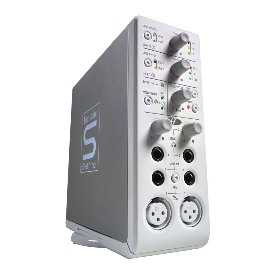
Front panel facilities and controls

- Input select and gain adjust
The top two sections allow the gain of the two analogue inputs to be adjusted using the corresponding dials. The level of the respective input is indicated by the triple LED dBFS meter next to it, a healthy level having a permanently illuminated green LED with occasional yellow LED flickering but no red O/L LED, which signifies that digital clipping is occurring. The Line input button allows either a line-level or Instrument source (connected to the front panel 1/4 " TRS jack input) to be chosen, as indicated by the corresponding LED. - Monitor level controls
The dial in this section provides a control over the level of one or more monitor signal(s) dependent upon the settings of the SaffireControl software (this defaults to a level control for all outputs), with buttons to dim (reduce the level by 12dB) or mute as required. Hardware control of each stereo output can be toggled using the (H) button next to its volume control.
- Digital and MIDI displays and control
When an SPDIF (digital) signal is connected to the SPDIF RCA (phono) input on the rear panel, the SPDIF In LED in this section will illuminate. Similarly, the MIDI In and Out LEDs will light when a MIDI signal is received and transmitted respectively. When the MIDI Thru button is active, indicated by the corresponding LED, the MIDI data received at the MIDI Input will be sent directly to the MIDI Output, without needing to launch any sequencing software. - Headphones outputs and level controls
This section features two stereo 1/4" TRS jack connectors for the independent headphones mixes. Not only can the level of each headphones signal be independently controlled (using the corresponding dial), but the balance of each signal can be set using the custom mix facility within the accompanying SaffireControl software. - Microphone and line inputs
Front panel inputs are supplied for both microphone and line-level sources. Plugging in a source to one of the Line Inputs will deactivate the corresponding Mic Input, so ensure that nothing is connected to the Line Input if wishing to record through the Mic Inputs. If phantom power is required, simply press the 48V button above the Mic Inputs, which supplies phantom power to both inputs. If you are using a condenser microphone then this switch will need to be engaged. If you are unsure whether your microphone requires phantom power, refer to its user guide as phantom power will damage some microphones, most notably ribbon microphones.
Rear Panel Connections

- Eight balanced analogue outputs on 1/4 TRS jack, labelled 1-8 in ascending order from bottom to top
These could be used for mixing in 7.1 (or 5.1) surround so the outputs are marked with Left, Right, Centre, LeftSurround, RightSurround, LowFrequencyEffects, LeftCentre and RightCentre accordingly. If using 5.1, ignore ouputs 7 and 8 (LeftCentre and RightCentre). - DC power adaptor input
This means that the interface can be powered by an external PSU if required. The most common (larger, 6 pin) type of Firewire port can supply power, so the use of an external power supply will not normally be necessary. However, if the connected computer/laptop only features the smaller 4-pin Firewire connector, which cannot supply power, then the PSU must be connected. - Two RCA (phono) connections
These enable a digital SPDIF signal to be inputed and outputed. As an SPDIF signal is stereo, this enables a total of four channels to be recorded simultaneously, for example two separate mono sources (voice and guitar) from microphone inputs on the front panel, at the same time as recording a stereo SPDIF signal sent from a synthesizer, outboard with digital I/O or additional DAW. - Two standard 5-pin MIDI connectors
These allow MIDI data to be received from external MIDI equipment and transmitted from the sequencer to the DAW (Digital Audio Workstation — most likely your computer) via the firewire connection. Alternatively, if the Saffire s MIDI In is connected to a controller keyboard s MIDI Out and the Saffire s MIDI Out is connected to a sound module s MIDI In, pressing the MIDI Thru button on the front panel will enable the MIDI data to pass from the controller keyboard to the sound module without having to launch any sequencing software. - Two Firewire 400 ports
These allow connection to the computer for streaming of data and, (if connected to an identical type of Firewire port), supply of power to the unit. Either port can be used for this purpose, leaving the additional port free for connecting to other Firewire equipment (e.g. hard drives) should the Saffire be using up the only available Firewire port on the computer. The nature of Firewire connectivity means that chaining equipment in this way is possible and will act as if the equipment is connected directly to the computer through separate Firewire ports.
Recording and monitoring a source using Saffire

This guide aims to give you a few simple instructions and tips on how to get audio in and out of your computer using Saffire and the accompanying software SaffireControl. For more detailed instructions, consult the relevant sections of the Saffire User Guide and help files at www.focusrite.com.
Once the drivers have been installed, the sequencer/ recording software is up and running and the Saffire has been correctly set up as the selected audio interface, audio can be recorded.
- First, open up the SaffireControl application and then connect 1/4 " TRS jack outputs 1 and 2 on the rear of the hardware to your amp or speakers (depending on whether they are active or not). Alternatively, just plug some headphones into the Headphones 1 socket on the front panel.
- To record a mono source like a vocalist or guitar player, simply plug a microphone into the left hand XLR socket on the front of the Saffire hardware and press the 48V (phantom power) button if required.
Phantom power is only necessary if using a condenser microphone; almost all dynamic microphones will be unaffected, but ribbon microphones may be damaged. - Now get the artist to play or sing and set the level of the input using the gain adjustment knob on the front panel. Rotate the dial clockwise to increase the level, making sure that the O/L LED (top red LED) never illuminates as this indicates that the level is exceeding the maximum level of the digital converter (clipping point).
For an even easier indication of level, observe the level of the meter in the top left of the SaffireControl window (as shown in the diagram). - Switch to tracking (recording) mode by pressing the TRACK button in the bottom right of the full SaffireControl window (not shown in the diagram).
SaffireControl boots up in S/CARD (soundcard) mode, which is a preset where only the (playback) tracks from the sequencer are heard. - You will now hear the input source routed to your monitors and/or headphones.
The recorded source should be heard on both headphones and monitors as the INPUT MIX-P/BACK MIX sliders will all be in a central position. This means that equal amounts of the (playback) tracks from the sequencer and the incoming audio will be sent to each stereo output pair. If you wish only to monitor the audio being recorded then move this slider to the extreme left position. - Adjust the level of the monitors, if connected, by using the Monitor dial on the front of the hardware (providing the Hardware (H) button is illuminated in the o/ps 1 and 2 section (see diagram). The headphones level can also be adjusted using the headphones gain dial on the front panel (above the headphones output).
Soundcard (S/CARD) mode
SaffireControl boots up in Soundcard (S/CARD) mode, which is the mode to use if wanting to send outputs 1-8 from a sequencer straight out of analogue outputs 1-8 of the Saffire for mixing/monitoring purposes. Pressing the TRACK (tracking/recording) button on the bottom right of the SaffireControl window changes the software to recording mode, where both inputs and outputs are heard. To return to S/CARD mode, simply press the S/CARD button in the bottom right of the SaffireControl window. This bypasses the complex monitoring and foldback options of SaffireControl and simply makes Saffire behave like a 10-output (1-8 analogue, 9-10 digital) soundcard. Pressing the S/CARD and TRACK buttons within SaffireControl and seeing/listening to the results is a good way to get to grips with the software and learn how various SaffireControl settings affect the function of the hardware.
SaffireControl
Session Management & Advanced Settings Software
SaffireControl is a software application that allows total control of the Saffire hardware, so that plug-ins can be applied and different input and playback mixes can be created. The software has two main modes of operation, which allow the hardware to function either as a comprehensive tracking (recording) tool, with custom foldback mixes (of incoming audio and playback tracks from a sequencer) for artists, or as a standard soundcard, with eight analogue outputs. Buttons within the main software application instantly recall these two types of interface performance and, of course, all settings within one or the other mode can be saved so that a session can be picked up again at a later date (see SOFTWARE SETTINGS. SaffireControl initially boots up in S/CARD mode where none of the inputs are monitored (see PROCESSING/MIXING OF STEREO OUTPUTS) but, after using the application for the first time, the previous settings will always reload upon booting.
Main Application Window

The main application window is where the general session settings are configured, complete with multiple faders for all incoming and outgoing audio and vertical strip meters for each stage of the audio chain. This is divided into three main sections - input processing, balancing of audio from the sequencer (e.g. Cubase) and separate processing/mixing of all stereo outputs (monitor and headphone paths). The software can be set to whatever level of complexity is required by the engineer/session, with simple controls on the surface and more advanced settings always visible but activated at the user s command. Once settings have been defined, SaffireControl can be shrunk down to a condensed format and can be set to float continuously over whatever recording software is in use. There are two keyboard shortcuts offering enhanced control of the application; shift and click offers fine rather than coarse control of pots, whilst alt and click returns any control to the default setting.
Input stage

The Input stage, in the top left of the main software panel, is the area where both EQ/Amp Sim and/or compression can be applied to analogue Inputs 1 and 2. There are also meters showing the level before and after processing; the meters to the left of each channel s plug-in settings show the level of the input directly after converting to digital and the meters on the right show the level after the EQ/Amp Sim and/or compression has been applied. Set the level of the analogue inputs before adding EQ or compression using the corresponding dials on the front of the Saffire hardware.
A stereo link button is included at the bottom of analogue input 1 for linking the two analogue inputs if a stereo signal is being recorded. Clicking the button activates stereo linking mode, which disables the analogue Input 2 controls, as both are now controlled by analogue input 1, and replaces all the controls in the Input balance section of the outputs settings section with one dial to mix between inputs 1/2 and 3/4 (see PROCESSING/MIXING OF STEREO OUTPUTS section).
If wanting to apply EQ and/or compression then simply click the buttons within the Input stage to activate the relevant plug-in, open its separate window to modify settings or reverse the order of the plugins (as shown in the picture above). The default order of the plug-ins is compression then EQ/Amp Sim, with the first plug-in in the chain always sitting above the second. One mouse click on the relevant plug- in button opens up a separate window where the individual settings for that input channel can be defined (see relevant plug-in sections for details). A further button is provided to select either EQ or Amp Sim, as indicated by the LED and plug-in window launch icon.
On the right hand side of the Input stage section are two sets of stereo meters, representing the four input channels sent to the recording software in use. Inputs 1 and 2 will always be the two analogue inputs but inputs 3 and 4 can be one of two choices: the default setting for 3 and 4 is the same signal as inputs 1 and 2 but without processing (the dry analogue input signals) which means that a backup of the recorded signals can be tracked, and EQ, compression and other effects added at a later date. Alternatively, if the S/PDIF button below the meters for inputs 3 and 4 is activated then inputs 3 and 4 receive their signal from the SPDIF inputs. The SPDIF In LED on the front of the Saffire hardware must be illuminated for a signal to be received in this mode and a valid SPDIF signal connected to the RCA (phono) input on the rear panel.
EQ

Equalisation of sound is an essential part of the recording process, necessary to remove or boost various sections of the audible frequency spectrum. The Saffire EQ is 4-band parametric, with the option of shelving and high/low-pass on bands 1 and 4, and exhibits the same curves as the classic Focusrite EQ; all that s required to sculpt sound with truly professional flair! Each analogue input has two buttons within the Input Stage of the Main Application window that insert the EQ or Amp Sim in the channel path and launch the EQ or Amp Sim window (see Input Stage for details). Make sure that the EQ LED below these buttons is illuminated and the correct icon is displayed when attempting to launch the window, otherwise the Amp Sim window will open instead.
The EQ window functions in two modes, template mode and advanced mode. When the EQ window is first launched, the EQ will be switched off for that input (as shown by the inactive LED) and will be set flat in template mode. To switch to advanced mode, simply press the mode button on the right of the EQ window just to the left of the OUT fader (as shown in the diagram) that alternates between the two modes. The LED button on the left activates/bypasses the EQ from within the plug-in window. Two faders at either end control the gain of the signal before and after EQ.
In advanced mode, all areas of the four band parametric EQ can be adjusted. When the plug-in is first launched, the advanced mode will be loaded but set flat, i.e. with no gain increase or decrease at any stage over the entire frequency range. All four EQ bands have three dials each to adjust the frequency (FREQ), Gain and Q of the EQ band. Rotating the dials clockwise will increase the value in each case, the exact numerical value being displayed in a box below the dial whilst rotating and when the mouse cursor moves over it. The outer two bands controlled by each set of three dials on either end of the panel can be independently set to be band pass (as default), high/low shelf (middle button) or high/low-pass (bottom button) by pressing the corresponding small buttons at either end as shown in the diagram. When in high/low shelf mode, only the GAIN and FREQ dials will be active for that band, and when in high/low-pass mode, only the FREQ and Q dial will be active to select the cut-off frequency of the filter. For example, if wanting to set up a low shelf to increase the bass, press the middle button on the left and then rotate the GAIN dial on the first band (on the left) clockwise. If wanting to insert a low-pass filter in the signal path to cut out high frequencies, press the bottom button on the right and then rotate the FREQ dial on the last band (on the right) to set the cut-off frequency for the filter (above which all frequencies will not be heard).
In template mode, the slider is used to select a different preset EQ configuration, such as one ideally suited to recording vocals, guitar, percussion and so on. Click on the desired slider position and the slider will jump to it. (These templates have configured the EQ controls for all four bands available within the advanced mode {the lower controls} so that the dials above control the main sonic characteristics of the source being recorded). For example, with the slider in the Vocal position, the four knobs in template mode relate to the warmth, presence, harshness and breathiness respectively. Rotating the knobs in a clockwise direction increases the amount of this property. This does not necessarily mean just increasing the gain of that EQ band but could be both the gain and Q for instance.
If wanting to set up your own EQ settings starting with a particular template, simply click the mode button to switch to advanced mode and adjust the controls as detailed above.
Two buttons in the bottom right of the EQ window allow copying and pasting of EQ settings to and from other Saffire EQ locations, running in SaffireControl or on the host.
Amp Sim

The Amp Sim plug-in is designed to allow high quality tracking of guitar parts without the need for a whole host of physical amplifiers. With Saffire, the guitar can simply be plugged direct into the front panel input and the Amp Sim plug-in can be activated, offering four different amplifier simulations from the world s best collection.
Each analogue input has two buttons within the Input Stage of the Main Application window that insert the Amp Sim or EQ in the channel path and launch the Amp Sim or EQ window (see Input Stage for details). Make sure that the AMP LED below the buttons is illuminated and the correct icon is displayed when attempting to launch the window, otherwise the EQ window will open instead.
The Amp Sim window has an LED button on the left activate/bypass the amp similation. When the window is first launched, the button will be illuminated to show that the plug-in is active; click the button to bypass as required. A slider is featured to allow different classic amplifier simulations to be selected. Simply click on an area of the slider to select an amplifier, the slider will jump to whatever area is clicked.
Five dials are included to allow control over the amp s settings. The first is DRIVE, which increases the level of distortion when rotated clockwise. The next three are for adjusting the EQ of the amp sim; rotating the dials clockwise increases the gain of the LOW, MID and HIGH frequency bands respectively from left to right. The last dial sets the GAIN of the output of the plug-in; rotate clockwise to increase. The levels of all dials are indicated by the blue surrounding lines, with precise numerical values shown while rotating or while the mouse cursor passes each dial.
Two buttons in the bottom right of the Amp Sim window allow copying and pasting of Amp Sim settings to and from other Saffire Amp Sim locations, running in SaffireControl or on the host.
Compression

The Saffire Compressor plug-in is modelled on the legendary Focusrite hardware devices, with individually tuned optos to help create the sound of vintage 1960s compression. The plug-in can be used to squash the dynamics of a sound in varying degrees, e.g. remove the sudden loud bursts, so that the overall level can then be turned up to make the signal as loud as possible. A compressor essentially acts like an automatic volume control, turning down the volume of a signal if it gets too loud. This reduces variation between loud and quiet passages, as it automatically reduces the gain when the signal exceeds a given volume, defined as the threshold. Using the Saffire Compressor helps to even out a performance, stopping a signal from clipping and/or disappearing in the mix, and can also give it a whole new sonic character. Each analogue input has two buttons within the Input stage of the Main Application window that insert the Compressor in the channel path and launch the Compressor window (see Input Stage for details).
The Compressor window functions in two modes, template mode and advanced mode. When the window is first launched, the Compressor will be switched off and set flat in template mode. To switch to advanced mode, simply press the mode button on the right of the Compressor window just to the left of the OUT fader (as shown in the diagram) that alternates between the two modes. The LED button on the left activates/bypasses the Compressor from within the plug-in window. Two faders at either end control the gain of the signal before and after compression.
In advanced mode, the full range of standard compressor controls are available. The first dial to set is the threshold (THRESH), which sets the level at which compression begins. The lower this value is set, the more of the signal will be compressed as the audio will compress when the threshold is reached. Rotate the THRESH dial anticlockwise to lower the threshold and so increase the compression.
Set the RATIO next, as this determines how much the signal is reduced by when it exceeds the threshold. For example, a ratio of 10:1 means that when the level of the uncompressed signal exceeds the threshold by 10dB, the compressed signal will only increase by 1dB.The higher the ratio therefore (the further the dial is rotated in a clockwise direction) the more heavily the signal is compressed. The next dials to set are the ATTACK and RELEASE times of the compressor, fastest/shortest position being fully anticlockwise and slowest/longest being fully clockwise. The ATTACK time defines how quickly the compressor kicks in, e.g. how fast the signal is turned down when it exceeds the threshold. In other words, setting a slower/longer attack time by rotating the dial clockwise will mean more of the loud part of the signal gets through uncompressed, which makes the signal much more punchy but also more likely to clip. The RELEASE time defines how quickly the compressor stops acting on the signal after it has begun to compress. Setting a quicker/shorter release time by rotating the dial anticlockwise will normally make the signal louder overall, however this is dependant on how often the level exceeds the threshold and how fast the attack time is.
Last but not least, the GAIN dial defines how much the level of the compressed signal is increased after compression. This means that a heavily compressed signal can be turned up loud to give it much more presence without fear of any overload or clipping occurring. The Gain Reduction (GR) vertical meter to the right of the plug-in window indicates the amount of compression taking place, which provides a visible means of determining the Compressor s effect. All dials have a surrounding blue line to show their value, with the exact numerical amount displayed whilst rotating and when the mouse cursor moves over the dial. For those new to compression and wanting to hear its effect in the most obvious way, turn the THRESH down low and the RATIO up high, then set the ATTACK dial fully anti-clockwise and the RELEASE to a fairly low value also. Now experiment with the parameters, adjusting the attack time and so on, to see how this affects the sound.
Two buttons in the bottom right of the Compressor window allow copying and pasting of Compressor settings to and from other Saffire Compressor locations, running in SaffireControl or on the host computer.
Balancing tracks from the sequencer/recording platform

The top right hand side of the Main Application window has five faders, which represent the levels of the first 10 tracks from the sequencer/recording platform. The faders from left to right signify tracks 1-10 in ascending stereo pairs (labelled S/W 1/2-9/10).The level of this fader signifies the level respective to the level set within the software/sequencer, whereby 0dB (maximum fader setting) is the exact level of the gain value set within the software/sequencer, and lowering the fader will reduce it. For example, when SaffireControl is first launched, the faders within the Main Application window will all be set to 0dB so that the level of all 10 tracks will be identical to that set within the software/ sequencer.
The mix created with these faders will become the default output signal sent to each set of the stereo outputs, controlled by the lower section of the Main Application window. However, if an independent custom mix is required for any stereo output then one can be created using the custom mixes within SaffireControl (see PROCESSING/MIXING OF STEREO OUTPUTS section on the following MIDI Operation). To listen to the balance created in this section, if speakers are connected to the main monitor outputs (1/4 TRS jacks 1 and 2 on the rear panel), then set the input/ playback horizontal slider to the fully right (playback) position and make sure that the custom mix button below the slider (for S/W tracks) is not selected. See next section for more details.
Processing/mixing of stereo outputs

The lower half of the Main Application window is the area where the signal sent to each set of stereo outputs (monitors, headphones, SPDIF Out etc) can be mixed and processed, meaning the exact levels of each input channel and each of the ten playback tracks from the sequencer can be set and reverb applied. Each stereo output has its own section, with the stereo pairs positioned in ascending order from left to right. The stereo output sections are all identical except for the last one, 9/10, which is the SPDIF output and so contains no level control as the digital output level is fixed. This section of the Main Application window will change when the stereo link button in the Input Stage section is active (see STEREO LINK BUTTON CONTROLS section).

The top segment of each stereo output portion is devoted to mixing the levels of the input channels. This may simply be a case of blending between analogue inputs 1 and 2 (probably most common) or inputs 3 and 4 (either dry signal or SPDIF In) or it might be a custom mix of all four input channels. If simply wanting to blend between analogue inputs 1 and 2 then the dial labelled IN 1/2 BAL can be used. When the dial is fully anticlockwise, the signal will just consist of analogue input 1, and when the dial is fully clockwise, the signal will just consist of analogue input 2.When the dial is positioned centrally, the input mix will be an equal balance between inputs 1 and 2. (These levels are represented by the blue lines that surround the dial.) If a blend of inputs 3 and 4 are required then simply press the button below the dial labelled 3/4, which changes the dial above to now blend inputs 3 and 4 in the same way as 1 and 2. NB: Make sure this button is not active if wanting to blend inputs 1 and 2.
If a more complex mix of all four input channels is required then one can be created with the custom mix feature. Simply press the larger button with the mini faders displayed on it to launch a separate window where a custom mix can be created. When the window is launched, the custom mix on/off button will be triggered (selecting the custom mix option) and will illuminate. This will mean that the input blend dial to the left (described above) will not be active. If wanting to return to normal input blend mode then simply press the custom mix on/off button again to deselect it.

The inputs custom mix window displays all four input channel faders, allowing a unique mix to be created for the stereo output currently being modified. Once a mix has been set, this mix can always be seen in reduced format on the custom mix window launch button, so the mix can always be viewed, even when the custom mix window is closed. If the custom mix on/off button is deactivated then this reduced format mix will change to the mix set by the blend dial to its left, so the currently selected mix will always be shown. Two dials and buttons within the inputs custom mix window also allow specific amounts of reverb to be set for input channels 1 and 2. This amount of reverb overrides the global amount for that stereo output pair (note the main reverb dial on the corresponding input mix section of that stereo output channel is greyed out). Rotate the dial clockwise to increase the amount of reverb and use the activation button to select or deselect the reverb (reverb is active when button is illuminated).
Once a balance of the input channels has been created, the main reverb dial can be used to add reverb to the channels 1 and/or 2 (in different proportions if required, set in the custom mix window). Press the button to activate the reverb (illuminated when active) and rotate the dial clockwise to increase the amount of reverb. See FOLDBACK REVERB section for details on how to modify reverb settings.
This mix of inputs now becomes the INPUT MIX for that pair of outputs on the horizontal slider (crossfader). If just wanting to listen to this mix, with none of the P/BACK MIX signal (tracks from sequencer), then ensure that the slider is in the extreme left position. Moving the slider to the right will introduce small amounts of P/BACK MIX until the slider is in the central position, when equal amount of both signals will be selected. Moving the slider to the right will then decrease the INPUT MIX gradually until only the P/BACK MIX is heard when the slider is in the extreme right position.
The P/BACK MIX will be the generic mix selected in the BALANCING TRACKS FROM THE SEQUENCER/ RECORDING in the BALANCING TRACKS FROM THE SEQUENCER/ RECORDINGPLATFORM section (the faders in the top right of the Main Application window) unless the S/W custom mix button below the slider is active, in which case it s independent of these S/W faders. The two custom mix buttons below the slider allow a custom mix of tracks 1-10 from the sequencer/recording software to be created for that pair of outputs, rather than using the generic mix created with the five S/W faders. This allows the engineer to create a unique foldback mix of the tracks coming from the sequencer for even the most fussy artist, without having to change the mix set within the sequencer. Pressing the large custom mix button launches the S/W custom mix window.

This window features five faders which look identical to those in the top right of the Main Application window, representing the levels of S/W tracks 1-10 (outputs 1-10 coming from the recording software/sequencer).The faders have the same gain relationship to the software as those in the Main Application Window, meaning that if the faders are set to 0dB (maximum) then the levels of tracks 1-10 will equal those currently set in the recording software/sequencer. When this custom mix window is launched the custom mix on/off button (smaller button) will illuminate to signify that the custom mix is active. This means that the custom mix set within this window will become the P/BACK MIX for whatever stereo output is being modified, NOT the mix set by the faders in the top right of the Main Application window. If wishing to revert back to the mix set by the faders in the Main Application window instead then simply press the smaller custom mix on/off button to deactivate. In the same way as the inputs custom mix button above, the currently selected playback mix will be permanently displayed in reduced format in the custom mix window launch button so that the mix is always visible, even when the custom mix window is closed.
The bottom of each set of stereo output controls features a dial for setting the level (all except 9/10 - SPDIF) and a series of smaller buttons. To the left of the dial is a Mute button (labelled M), above is a button that sets the Monitor dial on the hardware to control the level (labelled H) instead of the software, and to the right is a Solo button (labelled S). Each dial illuminates when active. The Mute button cuts the output and the Solo button mutes (cuts) all other outputs. The set of controls for stereo outputs 1/2 has the Hardware Control button (H) active as default so that the Monitor control on the hardware sets its level, to deselect it simply press the button allowing software control. Outputs 1/2 controls also feature an additional button with a downward arrow; this dims the stereo output by 12dB (the same as pressing the dim button on the hardware). Note that 9/10 output controls (SPDIF) do not have a level dial or a Hardware Control button, just Mute and Solo.
Foldback Reverb

The reverb dial in every stereo output section sets the amount of foldback reverb (not recorded reverb, just for the headphone/monitor mixes) applied to analogue input(s) 1 and/or 2 as required, with a smaller button that turns the reverb on or off. If wanting to set reverb parameters then the plug-in window can be launched in the same way as the EQ and Compressor windows in the Input stage, by pressing the plug-in icon located to the right of the Main Application window, below the Saffire logo.
If recording two separate mono inputs the reverb window will appear twice so that different types of reverb can be applied to each input. If recording a stereo source, one reverb window will appear to define the reverb for both inputs in the stereo pair.
The foldback reverb settings for the analogue inputs (across all outputs) are defined by three dials. The first dial, labelled SIZE, defines the size of the reverberant space, rotating clockwise to increase. The second dial, labelled DIFFUSION, modifies the absorption of the reverb, rotating clockwise to decrease (increasing the amount of reflected sound). The third dial, labelled TONE, filters the reverberant sound to create more low frequency (in the fully anticlockwise position) and more high frequency (in the fully clockwise position).The smaller button to the left of the dials has the same function as with the other plug-ins, to activate/bypass the plug-in (illuminated when active).
AU/VST Reverb
Although the reverb that functions within SaffireControl is for foldback only, an AU/VST version of all four plug-ins is available for use separately within the sequencer/recording software. Using the AU/VST plug-ins will mean they run off your computer s processor, unlike the SaffireControl plug-ins that run off the Saffire hardware s onboard DSP.The AU/VST reverb has identical controls to the reverb within SaffireControl (dials for Size, Diffusion and Tone) but instead of an off/on button within the plug-in window, there is a dial to mix between 100% dry (fully anticlockwise) and 100% wet (fully clockwise) signals.
Stereo link button controls
Pressing the stereo link button within the Input stage of SaffireControl results in a changing of the Main Application window format, as follows:

In this mode, analogue input 2 is disabled and settings for the stereo pair (inputs 1 and 2) are both controlled from analogue input 1. The reverb window (once launched) also changes in this mode, appearing only once so that foldback reverb for inputs 1 and 2 can be set equally (see FOLDBACK REVERB section for further details).The last change that the software undergoes is a simplification in the Input channel mixing stage within each set of stereo output controls; the IN 1/2 (or 3/4) BAL dial and custom mix buttons are replaced by one dial, which switches between inputs 1/2 and 3/4.
Software settings
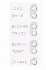
The bottom right section of the Main Application window has a series of buttons to define the main software settings like appearance and generic Saffire operation. The top two buttons are LOAD and SAVE. These allow all settings within your session to be saved as regular files at a destination of your choice on your computer and instantly recalled at a later date. The next two dials are presets for SaffireControl function. The top S/CARD button (default mode) should be pressed if the Saffire hardware is to act like a regular 10- output Soundcard and the lower TRACK button can be used at the start of recording session to make use of SaffireControl s extensive monitoring/foldback options. The S/CARD button is the one to use when not recording but simply wanting to send outputs 1-10 of the sequencer/recording software to outputs 1-10 (analogue outputs 1-8, SPDIF outputs 9-10), for example when mixing down.
Pressing the S/CARD button therefore sets the INPUT MIX-P/BACK MIX slider to the extreme right position so that just the tracks from the sequencer are heard, in addition to activating the custom mix output option and setting only the relevant S/W fader to 0dB, as can be seen in the image on the following page.

Pressing the TRACK button will change to the tracking (recording) mode in which a mix of input channels with optional foldback reverb and a mix of the playback tracks from the recording software/sequencer can both be blended for monitoring and foldback during a recording session. Pressing the S/CARD and TRACK buttons and seeing/listening to the results is a good way of getting to grips with how SaffireControl operates.
The next two buttons define how the software appears whilst tracking. The SHRINK button reduces the Main Application window to two smaller formats with only limited controls and the FLOAT button makes SaffireControl float permanently over the sequencer/ recording software so that it s always in view and easily accessible. Press the SHRINK button once to reduce to the first smaller format, and twice to shrink to the smallest format. An EXP button then allows the window to be expanded back to full size.
The last control is the S/RATE button, which launches a separate window in which the sample rate of the Saffire hardware s digital converter can be set.
To set a sample rate, simply click on the LED beside it, which will illuminate once selected. If the Saffire is currently being used to record then a sample rate cannot be selected and IN USE will be illuminated. If wanting to synchronise to an external source (via the SPDIF In signal) then press the EXT LED, which will illuminate once selected. Saffire will only be correctly synchronised to this source if LOK is illuminated next to it. If not, make sure that the sample rate of the incoming SPDIF signal is the same as the one set in this window.

MIDI Operation

The Saffire operates as a MIDI interface with one input and one output. The Saffire can operate in one of two possible MIDI modes. The state of the THRU button on the front panel determines which MIDI mode will be used.
Normal MIDI Mode: Input and output MIDI devices with a sequencer
When the THRU LED on the front panel is off, all midi received at Saffire s midi input will be routed to the computer via firewire, and will not be routed directly to the midi output. This mode is designed for use with a sequencer (eg Cubase) or some other software with MIDI capabilities. This mode is necessary when the sequencer is running, because it will prevent doubling of notes that occur when the same MIDI information is transmitted by both the input device and the sequencer.
MIDI Thru Mode: Input and output MIDI devices without a sequencer
When the THRU LED on the front panel is lit, all midi received at Saffire s midi input will be routed directly to the output. This mode is designed for simply passing MIDI through the Saffire. This may be useful when no sequencer is running, because you don t need to route MIDI in and out of you Mac or PC.
Saffire Signal Flow Diagram - Dual Mono Mode

Troubleshooting
LEDs on the Saffire hardware aren t working
- Does the unit have power? This is supplied by the Firewire cable, is one connected? If connecting to a 4-pin Firewire port, is the external PSU connected?
Saffire is not recognised as a valid audio interface by the recording software in use (e.g. Cubase)
- Is the hardware connected to the computer over Firewire?
- Have the drivers been correctly installed from the accompanying CD-ROM?
No signal when using mic inputs
- Is the unit powered correctly? See above.
- Is the gain dial of the corresponding input on the hardware set sufficiently high? Rotate clockwise to increase the level.
- Is something connected to the corresponding line input on the hardware? This will deactivate the mic input.
- For microphones that require phantom power (e.g. condenser mics), is the 48V switch on the front panel engaged? (If you are unsure about whether your microphone requires phantom power, check the user guide for your microphone.)
- If seeing but not hearing a level, is the slider for the monitoring pair of outputs far enough to the left (towards the INPUT MIX position)? If over to the right (in the P/BACK position), only the tracks from the sequencer will be heard.
No signal when using line inputs
- Is the unit powered correctly? See above.
- Is the gain dial of the corresponding input on the hardware set sufficiently high? Rotate clockwise to increase the level.
- Is the Line/Inst switch on the hardware set correctly? The LINE LED must be active.
- If seeing but not hearing a level, is the slider for the monitoring pair of outputs far enough to the left (towards the INPUT MIX position)? If over to the right (in the P/BACK position), only the tracks from the sequencer will be heard.
No signal when plugging an instrument into the line inputs
- Is the unit powered correctly? See above.
- Is the gain dial of the corresponding input on the hardware set sufficiently high? Rotate clockwise to increase the level.
- Is the Line/Inst switch on the hardware set correctly? The INST LED must be active.
- If seeing but not hearing a level, is the slider for the monitoring pair of outputs far enough to the left (towards the INPUT MIX position)? If over to the right (in the P/BACK position), only the tracks from the sequencer will be heard.
The compressor is not working
- Is the plug-in active? The small switch on the left of the plug-in window must be illuminated as well as the compressor on/off switch within the main application window (for the relevant input channel).
- Are the compressor controls set correctly? The threshold must be low enough for the signal to exceed it for the compressor to have any effect.
The EQ is not working
- Is the plug-in active? The small switch on the left of the plug-in window must be illuminated as well as the EQ on/off switch within the main application window (for the relevant input channel).
- Are the EQ controls in a position to have an effect on frequencies that are present in the signal? For example, a low-pass filter working on the upper frequencies will have little effect on a bass part.
The Reverb is not working
- Is the reverb plug-in active to the channel?
- Is the reverb plug-in assigned and active on input mix window?
- Is Reverb active in input mix section of the relevant stereo output port?
- Is the tone control set to an extreme position in the reverb plug- in window?
No signal heard at one of the outputs
- Is the level of the corresponding pair of outputs set high enough (either within SaffireControl or on the hardware)?
- Is the Mute button for the corresponding pair of outputs activated (either within SaffireControl or on the hardware)?
- Is the Dim button activated within SaffireControl or on the hardware (only outputs 1/2)?
- Are the 'mix' controls for that pair of outputs correctly configured for the signal being monitored? Each pair of outputs has its own set of controls used to determine what audio is heard (a mix of inputs and/or sequencer tracks), located in the bottom half of the SaffireControl software panel.
No tracks heard from the sequencer
- Do the tracks within the sequencer have sufficient level? The level set by the faders in the top right of the SaffireControl window are respective to that set within the sequencer.
- Is the slider for the monitoring pair of outputs far enough to the right (towards the P/BACK MIX position)? If over to the left (in the INPUT MIX position), only the tracks being recorded will be heard.
Cannot set a sample rate
- Is the Saffire being used to record audio? Whilst audio is being recorded, IN USE will show and the sample rate cannot be selected.
Cannot lock to an external device
- Is a valid SPDIF source connected to the SPDIF Input on the rear panel?
- Is the Saffire hardware set to the same sample rate as the digital audio received at the SPDIF In? If not, a Lock cannot be achieved.
Specifications
ANALOGUE INPUTS
Mic: 2 x XLR on front panel
Mic Gain: +13 dB to + 60 dB
Line: 2 x 1/4 TRS Jack
Line Gain: -10 dB to +36 dB
Instrument: As above, switched to Instrument
Instrument Gain: +13 dB to +60 dB
ANALOGUE OUTPUTS
Line level: 8 x 1/4 balanced TRS Jack
Nominal output level: 0 dBFS = 16 dBu, electronically balanced
All outputs are useable as monitoring outputs
DIM switch: 12dB attenuation
DIGITAL I/O
2 x SPDIF (RCA phono) on rear panel (24-bit, 192kHz)
Output transformer isolated
MIDI I/O
1 in / 1 out (and Thru) on rear panel
FIREWIRE
2 x S400 ports
POWER
Either via FIREWIRE or external PSU (included)
HEADPHONE MONITORING
2 x 1/4 TRS Jack on front panel (mirrors outputs 5-8)
MIC
Frequency Response: 20Hz - 20kHz +/- 0.1 dB
THD+N: 0.001% (measured at 1kHz with 20Hz/22kHz bandpass filter)
Noise: EIN = >120 dB (measured at 60 dB of gain with 150‰ termination and 20Hz/22kHz bandpass filter)
LINE
Frequency Response: 20Hz - 20kHz +/- 0.1 dB
THD+N: 0.001% (measured with 0 dBFS input and 22Hz/22kHz bandpass filter)
Noise: -88 dBu (22Hz/22kHz bandpass filter)
INSTRUMENT
Frequency Response: 20Hz - 20kHz +/- 0.1 dB
THD+N: 0.004% (measured with 0 dBu input and 20Hz/22kHz bandpass filter)
Noise: -87 dBu (20Hz/22kHz bandpass filter)
DIGITAL PERFORMANCE
Clock Source: Internal clock or sync to word clock from SPDIF inputs A/D Dynamic Range 104 dB A weighted
D/A Dynamic Range 110 dB A weighted Clock Jitter < 250 pico seconds
Sample rate 44.1 to 192 kHz
WEIGHT and DIMSENSIONS
1.1kg
6.5cm x 17cm x 17cm
POWER REQUIREMENTS
12v AC @ 1A
SYSTEM REQUIREMENTS
Macintosh
OS: OS X 10.3.3 or later
CPU/Clock: G3/800MHz, G4/700MHz
G4/1.2GHz or higher recommended for 192kHz operation Memory: 256MB minimum
PC
OS: Microsoft Windows XP Home Edition/XP Professional
CPU/Clock: Pentium, Celeron or Pentium compatible processor 900MHz or higher
Memory: 256MB minimum

Documents / Resources
References
Download manual
Here you can download full pdf version of manual, it may contain additional safety instructions, warranty information, FCC rules, etc.
Download Focusrite Saffire - Professional Multi-Channel Firewire Audio Interface Manual
Advertisement
Thank you! Your question has been received!


Need Assistance?
Do you have a question about the Saffire that isn't answered in the manual? Leave your question here.