Table of Contents
Advertisement
Quick Links
Advertisement
Table of Contents

Related Manuals for Harman Lexicon PCM96 Surround


Summary of Contents for Harman Lexicon PCM96 Surround
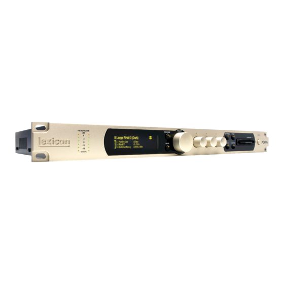
- Page 1 Surround Professional Audio Equipment...
- Page 2 WARRANTY This warranty is valid only for the original purchaser and only in the United States. If outside the United States please contact the local Lexicon ® distributor. 1. Please register your product online at . Proof-of-purchase is considered to be the responsibility of the consumer. A copy of the original purchase receipt must be provided for any warranty service.
-
Page 3: Table Of Contents
TABLE OF CONTENTS INTRODUCTION ����������������������������������������������������������������������������������������������1 THE FRONT PANEL �����������������������������������������������������������������������������������������2 THE REAR PANEL - DIGITAL MODEL �����������������������������������������������������������������4 THE REAR PANEL - DIGITAL AND ANALOG MODEL ������������������������������������������5 USING THE PCM96 SURROUND ���������������������������������������������������������������������6 Powering Up the PCM96 Surround ............6 The Preset Screen ..................6 Selecting Your Audio Source and Clock Source ........7 Loading a Preset ..................7 Changing Categories ................7... - Page 4 Card Config ...................23 Network Config ..................23 HiQnet Config ..................23 Restore Factory Defaults .................23 MACHINE MENU �������������������������������������������������������������������������������������������24 Soft Row Setup ..................24 I/O Settings ....................24 Various Parameters .................24 USING MIDI �������������������������������������������������������������������������������������������������24 Setup Definitions ...................25 Preset Loading ..................25 How to Assign a Base Channel to the PCM96 Surround .......25 Channel Map (how channels map to machines) ........26 Bank Dump ...................26 Reverse Bank Dump (Bank “Load”) ............26...
-
Page 5: Introduction
INTRODUCTION Congratulations and thank you for purchasing the PCM96 Surround Reverb/Multi Effects Processor! Building on the success of the PCM96, the new PCM96 Surround offers more presets, more configuration options, and more inputs and outputs. The PCM96 Surround gives you industry standard reverbs and effects, with tremendous flexibility. -
Page 6: The Front Panel
THE FRONT PANEL SELECT MACHINE TAP/TEMPO STORE FLASH BUSY LOAD COMPARE BACK 1. Gain LEDs Each row of Gain LEDs indicates input signal strength of each of the PCM96 Surround’s inputs. If the Audio Source is set to Analog (in the Audio Setup menu), they show analog levels. - Page 7 9. Power Button Press to turn the PCM96 Surround on or off. 10. Display This high resolution, high contrast, and high viewing angle OLED (Organic LED) display shows menu and box configuration and status information. 11. BACK Pressing this button moves you up one level in the menu tree. Note that when a System preset is loaded, this button takes you to the System Mode Category Selection menu.
-
Page 8: The Rear Panel - Digital Model
THE REAR PANEL - DIGITAL MODEL OUT 5-6 OUT 3-4 OUT 1-2 IN 5-6 IN 3-4 IN 1-2 1. POWER JACK Standard 3-pin IEC power connector. 100-240V, 50-60Hz automatic switching to correct voltage range. 2. ETHERNET INPUTS These RJ-45 connections are used to network PCM96 Surround devices and control them via Ethernet. -
Page 9: The Rear Panel - Digital And Analog Model
THE REAR PANEL - DIGITAL AND ANALOG MODEL ANALOG I/O 1. POWER JACK Standard 3-pin IEC power connector. 100-240V, 50-60Hz automatic switching to correct voltage range. 2. DB25 6-CHANNEL DIGITAL AES I/O This D25 connector carries six analog inputs and outputs. 3. -
Page 10: Using The Pcm96 Surround
USING THE PCM96 SURROUND POWERING UP THE PCM96 SURROUND 1. Plug in the power cord. 2. Press the Power button. 3. The Lexicon logo appears, and remains until the boot process is com- ® plete. Next, the Preset screen appears, showing the currently loaded pre- set. -
Page 11: Selecting Your Audio Source And Clock Source
SELECTING YOUR AUDIO SOURCE AND CLOCK SOURCE 1. Press the Machine button until the words “System View” appear in the Display. 1:ConcertHall->Flange 1:Single Stereo Config (System View) (System View) 2. Press the Select knob. The System Menu appears. System Menu Version 1.0 +Audio Setup +Machine Config... -
Page 12: System Presets And Machine Presets
System Presets and Machine Presets also have User and Card categories, where you can access user-edited presets. Presets in the User category are stored on the PCM96 Surround, and presets in the Card category are stored on a Compact Flash card. To select a different category 1. -
Page 13: The Configuration Icon
depending on what kind of preset is loaded. The following diagram shows what happens when you press the Select knob, Back button, and Machine button in both System View and Machine View. Preset Category Preset Category Selection View Selection View (System) (Machine) Press... -
Page 14: Editing A Preset
0:Med Hall 0:Med Hall 1:PreDelay :14ms 1:PreDelay :14ms 2:MidRT :1.59s 2:ReverbTime :1.59s 3:RvbOutFreq :4750.0Hz 3:RvbOutFreq :4750.0Hz Configuration Icon (Machine Preset) Press the Machine button repeatedly to cycle through the virtual machines in a System Preset, and eventually back to the System Preset. EDITING A PRESET To edit a System Preset, you must edit the virtual machines within it. -
Page 15: Storing A Preset
STORING A PRESET Once you’ve edited a preset, you can store it on the PCM96 Surround (in the User category) or on a Compact Flash card (in the Card category). Note: When you first insert a Compact Flash card, you may receive the message “Card Needs Initializing.”... -
Page 16: Initializing/Formatting A Compact Flash Card
INITIALIZING/FORMATTING A COMPACT FLASH CARD To initialize or format a Compact Flash card: 1. Press the Back button until the Preset screen appears. 2. Press the Machine button until System View is displayed. 3. Press the Select knob to enter the System Menu. 4. -
Page 17: Dsp Configurations
DSP CONFIGURATIONS The PCM96 Surround processor can be divided in up to four virtual machines, each of which can run its own algorithm. This lets you route sig- nals from each input through a variety of algorithm combinations. The PCM96 Surround can use up to six physical inputs and six physical outputs at a time;... -
Page 18: Single Stereo (Mono In)
When dealing with true surround source material, the choice of configu- ration is simple--choose the 4-in or 5-in version. The algorithms are all designed to treat the inputs uniquely. If the algorithm is a reverberator or room, then each input will propagate into the space from the direction of its virtual source. -
Page 19: Cascade Stereo
CASCADE STEREO The left and right signals are processed together in one virtual machine, and the resulting signal is sent to a second virtual machine, where they are again processed together. DUAL MONO The left signal travels through one virtual machine, and the right signal travels through a separate second virtual machine. -
Page 20: Single Four In Four Out
SINGLE FOUR IN FOUR OUT Four signals are processed by one virtual machine, and out- put as four signals. SINGLE TWO IN FIVE OUT Two signals are processed by one virtual machine, and out- put as five signals. SINGLE FIVE IN FIVE OUT Five signals are processed by one virtual machine, and out- put as five signals. -
Page 21: Networking
NETWORKING This section provides a step-by-step guide on how to properly connect the PCM96 Surround to a Local Area Network (LAN) for several different net- work architectures. The first topology is a simple direct connection using the provided Ethernet cable. The second method describes how to connect and configure several PCM96 Surround units to create an isolated network using an Ethernet switch with static IP addresses or with DHCP. -
Page 22: Connecting The Computer Directly To The Pcm96 Surround
SUBNET A small network within a larger network. For example, a TCP/IP network might be a subnet of a venue’s network, which could include computers throughout the building, or a network might be divided into subnets. For example, in a large installation, there may be one subnet per rack or room. DHCP (DYNAMIC HOST CONFIGURATION PROTOCOL) This is a protocol for automatically assigning IP addresses to devices on a network. -
Page 23: Virtual Private Networks (Vpn)
VIRTUAL PRIVATE NETWORKS (VPN) Virtual private networks (VPN) provide an encrypted connection (or tunnel) between networks or between a network and a user over a public network (such as the Internet). Instead of using a dedicated, real-world connection such as a leased line, a VPN uses virtual connections through the public network. - Page 24 ETHERNET LINK Make sure that you have a valid Ethernet connection by looking at the link status lights. Most Ethernet devices will have some kind of indicator that shows the link is present. Check the following connections: • PCM96 Surround device – If there is a valid connection on the PCM96 Surround you will see a solid green LED.
-
Page 25: System Menu
SYSTEM MENU The System Menu lets you adjust several settings in the PCM96 Surround. To access the System Menu, press the Select knob while a System Preset is loaded. The System Menu contains sub-menus and options. Sub-menus contain options and/or more sub-menus. To enter a sub-menu, highlight it with the Select knob and press the Select knob. -
Page 26: Machine Config
Confidence Error - “0” indicates no problem. “1” indicates the PCM96 Surround is detecting excessive jitter or noise on the digital audio line. No data has been corrupted, but corrective action should be taken. Sample Slip - An unchanging number indicates you are not slipping samples. -
Page 27: Tempo Control
Device ID Select the connected MIDI device’s ID here. Choose from 0-126. Base Channel Select the connected MIDI device’s base channel here. Choose from 0-15. Bank Dump Lets you copy an entire bank of presets from the PCM96 Surround to another device via MIDI. -
Page 28: Machine Menu
MACHINE MENU The Machine menu lets you adjust settings for a single virtual machine. To access the Machine menu, press the Select knob while a Machine Preset is loaded. The sub-menus vary depending on what algorithm is active. SOFT ROW SETUP This sub-menu lets you assign parameters to a Machine Preset’s soft row. -
Page 29: Setup Definitions
• Only has 1 to 3 PCM Devices SETUP DEFINITIONS Setup #1 – More Devices: This setup would be used in situations where you want to control more than 3 PCM Devices on the same MIDI port. This setup will control up to 16 PCM Devices. In this particular setup configura- tion, you cannot make specific patch changes on individual machines via MIDI;... -
Page 30: Channel Map (How Channels Map To Machines)
the unit. You can connect up to three PCM96 Surround units to a single MIDI device. To assign a base channel to the PCM96 Surround: Press the Back button until the Preset screen appears. Press the Machine button until System View is displayed. Press the Select knob to enter the System Menu. -
Page 31: Soft Row Parameter/Midi Cc Map
Continuous Controllers range from 0 to 127. If the parameter range is less than 127, then a small controller change might not result in a parameter update. But the entire range of the parameter can still be accurately con- trolled. In addition, if the actual range of the parameter is greater than 127, MIDI control might be somewhat coarse. -
Page 32: Midi Sysex Implementation
MIDI SYSEX IMPLEMENTATION COMMAND 0: REQUEST PRESET DUMP When this command is received by the PCM96 Surround, it will respond with a preset dump of the requested preset. If the preset does not exist, the PCM96 Surround will not respond. Only presets from User banks may be requested. - Page 33 COMMAND 2: REQUEST PRESET BANK DUMP When this command is received by the PCM96 Surround, it will respond with a series of preset dumps for all presets in the bank. Blank presets will be transmitted in a special form. Only presets from User banks may be request- ed.
-
Page 34: The Algorithms
THE ALGORITHMS CHAMBER (SURROUND, STEREO AND MONO) Chamber is a complex miniature-space effect resembling an echo chamber at its smaller settings and, at its larger ones, a small performance space with a more rapid build-up of reflection density than a hall. Reverberant tails are randomized. -
Page 35: Hall (Surround, Stereo And Mono)
Random Delays are similar to Simple Delays, but are especially useful for: • Multitap Tape Loops Feedback can be used to recirculate delays. Appropriate use of highpass and lowpass filters emulates the bandpass effects of multi-generational tape loops (hiss not included). Feedback diffusion allows emulation of azimuth misalignment –... -
Page 36: Random Hall (Surround, Stereo And Mono)
RANDOM HALL (SURROUND, STEREO AND MONO) Random Hall is a hall effect with gradual build-up, well suited to complex sounds like orchestral music. Its reverberators change over time in controlled random ways to avoid the buildup of tinny, grainy, metallic, or other color- ations. -
Page 37: Resonant Chords (Surround, Stereo And Mono)
RESONANT CHORDS (SURROUND, STEREO AND MONO) The Resonant Chord algorithm uses impulsive energy at the inputs to excite six resonant voices (notes). The level, pitch, duration, and high-frequency cutoff of the overtones for each voice are separately controllable. Each voice can be panned independently. -
Page 38: Chorus/Flange (Surround, Stereo And Mono)
the sustain pedal depressed.) In Res2>Plate, pitches are assigned to the six resonators diatonically, harmonized with the key, scale, and root of your choice. If MIDI note numbers are used to assign pitch, the resonators will constantly be re-tuned to harmonize with the incoming notes. CHORUS/FLANGE (SURROUND, STEREO AND MONO) Chorus/Flange is quite similar to other delay algorithms in the PCM96. -
Page 39: Pitch Shift - Standard Vso
work very differently, based on machine type. PITCH SHIFT - STANDARD VSO This simple pitch shifter provides high-quality shifting by semitones and cents. In stereo or surround, this is the best choice for full music mixes or for any multichannel submixes. Shifting on all channels is linked, so that the resultant soundstage remains stable. -
Page 40: The Parameters
THE PARAMETERS The PCM96 contains hundreds of presets, covering just about every possible need. But you can refine and customize any preset by adjusting its param- eters. Parameters are the building blocks within each preset that determine how it sounds and behaves. Each algorithm contains a set of parameters, and a variety of those param- eters (sometimes from more than one algorithm) are combined to create a preset. - Page 41 Chorus Depth (Concert Hall) This parameter controls the amount of randomization of the chorus tap. Higher values are generally preferred in order to minimize reverb coloration. Pitch effects may result and are closely tied to the Reverb Chorus Rate parameter. Chorus Rate (Concert Hall) This parameter controls the rate at which the reverb chorus is run.
- Page 42 Feedback This controls the amount of echo output that is fed back to the input of the echo buffer. The actual feedback level is modified by the Master Echo Feedback param- eter, if present. The master value is a percentage (0-100%) that is applied to the Echo Feedback level.
- Page 43 Lowest Shift Freq This tells the shifter the lowest frequency that it may be required to shift. As a general rule of thumb, this should be set in the higher part of the range in order to preserve detail in the shifted material. It should be lowered if arti- facts appear in the low frequencies.
- Page 44 Reflection Delay (Delay Time) A reflection delay is a delay tap taken from one of the inputs and sent to one of the outputs. It is often called a delay voice. Depending on the algorithm, there may be one or more reflection delays for each input channel. Some of the delays may mix their outputs to the same channel (left to left) and some may go cross-channel (left to right).
- Page 45 Reverb Spin (Spin) This is usually simply called spin. It controls the speed of the reverb random- izer. Spin is also connected with the Reverb Wander parameter Reverb Time Hi Cut This parameter, also known as Hicut or RTHC is a low-pass filter in the recirculating part of the reverb.
- Page 46 Tip: Shape will not have this effect if spread is at its minimum value. But even then, it can make a difference. In this case, it affects reverb tim- bre and density. Higher values of shape will be both darker and denser, although the effect is subtle.
- Page 47 Tail Width This parameter is present in all stereo reverbs and rooms. The reverb tail (all components of the reverb except for early reflections, etc.) is passed through a simple 2x2 matrix. This provides an encoding of the tail that dramatically changes its spatial characteristics.
-
Page 48: Analog Db25 Cable Diagrams
ANALOG DB25 CABLE DIAGRAMS (INPUT/OUTPUT) DB25 Pin Number Cable/Channel Number Cold Ground... -
Page 49: Digital Db25 Cable Diagram
DIGITAL DB25 CABLE DIAGRAM DB25 Pin PCM96 Surround Channel Not Used Not Used Digital Out 5/6- Digital Out 3/4+ Digital Out 3/4 Ground Digital Out 1/2- Not Used Not Used Digital In 5/6- Digital In 3/4+ Digital In 3/4 Ground Digital In 1/2- Not Used DB25 Pin... -
Page 50: Specifications
SPECIFICATIONS ANALOG INPUTS Connectors One 25-pin Dsub female connector Impedance 20K Ohm, balanced Level (for 0dBFS) +4dBu mode: +20dBu –10dBV mode: 8.2dBu Freq Response @96K 20Hz - 22kHz, ±.15dB 20Hz - 46kHz ±.5dB A/D Conversion 24 bits A/D Dyn Range 112dB unweighted, 115dB A-weighted <0.002% 20 →... - Page 51 CLOCK JITTER Intrinsic Exceeds AES3 Amendment 1 Jitter Gain Exceeds AES3 Amendment 1 CONTROL INTERFACES MIDI ** In/Out/Thru **supports program change ALGORITHMS Chamber Surround, Stereo and Mono Random Delay Surround, Stereo and Mono Random Hall Surround, Stereo and Mono Plate Surround, Stereo and Mono Dual Delay Surround, Stereo and Mono...
- Page 52 DIMENSIONS/WEIGHT Rack Units Size 19.0” W x 1.75” H x 16” D (483mm x 44.5mm x 317.5mm) Weight 14.25 lbs REGULATORY APPROVALS Class A EN55103-1, EN55103-2 UL1419 C22.2 EN60065 ENVIRONMENT Operating 15° to 35° C Storage –30 to 70 °C Humidity 75% relative humidity max RECOMMENDED CABLES...
-
Page 53: Midi Implementation Chart
MIDI IMPLEMENTATION CHART Function Transmitted Recognized Remarks Basic Default 1-16 Channel Changed Mode Default Messages Altered Note Number True Voice Velocity Note ON Note OFF After Keys Touch Channel Pitch Bend Control OX 32 OX 32 Bank Change Change OX 48-55 OX 48-55 Program OX 1-127... - Page 54 Part# 5047786-B Copyright 2016 Lexicon Professional ®...