Tronic 86620 Operating Instructions Manual
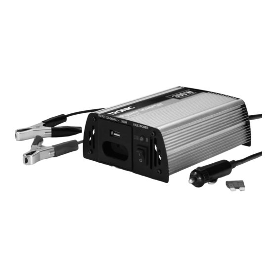
Power inverter
Hide thumbs
Also See for 86620:
- Operating instructions manual (33 pages) ,
- Operating instructions manual (33 pages) ,
- Operating instructions manual (33 pages)

Related Manuals for Tronic 86620


Summary of Contents for Tronic 86620
- Page 1 TRANSFORMADOR DE TENSÃO TSW 300 A1 TRANSFORMADOR DE TENSÃO POWER INVERTER Manual de instruções Operating instructions SPANNUNGSWANDLER Bedienungsanleitung IAN 86620...
- Page 2 Antes de começar a ler abra na página com as imagens e, de seguida, familiarize-se com todas as funções do aparelho. Before reading, unfold the page containing the illustrations and familiarise yourself with all functions of the device. Klappen Sie vor dem Lesen die Seite mit den Abbildungen aus und machen Sie sich anschließend mit allen Funktionen des Gerätes vertraut.
-
Page 4: Table Of Contents
ÍNDICE PÁGINA Introdução Utilização correcta Indicações de segurança Dados técnicos Elementos de comando Colocação em funcionamento Retirar da embalagem ........................4 Verificar o volume de fornecimento....................4 Indicações relativas ao funcionamento Instalação............................5 Funcionamento num veículo ......................5 Ligação a uma fonte de tensão ......................5 Ligação e funcionamento de uma carga/um aparelho Indicações relativas ao funcionamento de aparelhos Indicações gerais ..........................7... -
Page 5: Introdução
Introdução Indicações de segurança Parabéns pela compra do seu aparelho novo. • Este aparelho não deve ser utilizado por pessoas Decidiu-se, assim, por um produto de elevada quali- (inclusive crianças) com limitações das capaci- dade. O manual de instruções é constituinte deste dades físicas, sensoriais ou mentais ou falta de produto. - Page 6 Perigo de choque eléctrico! Perigo de incêndio! • Ligue o transformador de tensão apenas a uma • Não utilize o aparelho próximo de superfícies bateria de automóvel/uma tensão de bordo de quentes. 12 V. Se o aparelho for ligado a uma tensão de •...
-
Page 7: Dados Técnicos
Dados técnicos Elementos de comando Transformador de tensão Entrada DC Tensão: 12 V Ventilador (na parte de trás) Tensão máxima: 15,6 V LED de funcionamento/indicação de sobrecarga Consumo máximo de corrente: 40 A Interruptor para ligar/desligar Alarme de subtensão: a 10,5 ± 0,3 V Tomada 220-240 V para ficha europeia Desconexão por subtensão: a 10 ±... -
Page 8: Indicações Relativas Ao Funcionamento
Indicações relativas ao Instalação funcionamento • O transformador de tensão deve ser colocado numa superfície plana e sem irregularidades. Para o funcionamento contínuo de aparelhos através Certifique-se de que existe 1 m de espaço livre do transformador de tensão é necessário que exista em torno do transformador de tensão, para na tomada de bordo uma tensão entre 11 - 15,5 V assegurar a circulação do ar. -
Page 9: Ligação E Funcionamento De Uma Carga/Um Aparelho
Nota: Devido às elevadas resistências de passagem, pode acontecer que a conexão da ficha aqueça, ao utilizar um cabo com ficha de isqueiro de 12 V para automóvel . Por isso, no caso de fun- cionamento com cargas elevadas, não utilize o cabo de ligação com os bornes de ligação Fig.: ligação do terminal de cabos Ligação a uma bateria de automóvel... -
Page 10: Indicações Relativas Ao Funcionamento De Aparelhos
Atenção! • As cargas indutivas, como p. ex. televisores ou aparelhos estéreo (aparelhos com uma bobina No entanto, não ligue a carga/aparelho a ou um transformador) exigem frequentemente utilizar! uma corrente de conexão muito mais elevada • Ligue o transformador de tensão, colocando o do que as cargas de resistência com o mesmo interruptor Ligar/Desligar na posição I. -
Page 11: Substituição Do Fusível
Substituição do fusível Resolução de avarias gerais Perigo de morte devido a choque Televisores eléctrico: • O transformador de tensão é blindado e emite uma onda sinusoidal filtrada. Antes de substituir o fusível, desligue o transformador Em caso de recepção de, p. ex., emissoras de de tensão da alimentação de corrente. -
Page 12: O Sinal De Aviso De Tensão Da Bateria Reduzida Não Pára
Limpeza O sinal de aviso de tensão da bateria reduzida não pára. Perigo de morte devido a choque Possíveis motivos e ajuda: eléctrico: • A bateria está avariada. Substitua a bateria. • Alimentação de tensão ou de corrente insuficien- • Nunca mergulhe as peças do aparelho em te. -
Page 13: Importador
As reparações realizadas após o final do período de garantia comportam custos. Assistência Portugal Tel.: 70778 0005 (0,12 EUR/Min.) E-Mail: kompernass@lidl.pt IAN 86620 - 10 -... - Page 14 GB/MT INDEX PAGE Introduction Intended Use Safety information Technical data Operating Elements Initial operation Unpacking ............................14 Check the items supplied ......................14 Operational information Setup ...............................15 In vehicle operation ........................15 Connection to a voltage source ....................15 Connection and operation of a load/device Device operation information General notes..........................16 Low battery signal...
-
Page 15: Introduction
GB/MT Introduction device is to be used. Children should be supervised to ensure that they do not play with the device. Congratulations on the purchase of your new appli- • To avoid dangers remove the power inverter from ance. You have clearly decided in favour of a quality the vehicle receptacle and/or the connection ter- product. -
Page 16: Technical Data
GB/MT Technical data This device suitable only for use indoors. Risk of fire! DC Input • Do not use the device near hot surfaces. Voltage: 12 V • Do not locate the device in places exposed to Maximum voltage: 15,6 V direct sunlight, Otherwise, it may overheat and Maximum power become irreparably damaged. -
Page 17: Operating Elements
GB/MT Operating Elements Operational information For continuous operation of devices via the power Power inverter inverter the vehicle socket must supply a voltage Fan (on the rear panel) between 11 - 15,5 V . The voltage source of Operation LED/Overload indicator the vehicle socket can be perhaps an automotive On/Off switch battery or a regulated DC voltage like a transformer-... -
Page 18: Setup
GB/MT Setup • The power inverter should be positioned on an even, flat surface. Make sure that there is 1 cm free space remaining all around the power inverter for air circulation. • A distance of 50 cm must be maintained behind the fan's ventilation slots. -
Page 19: Connection And Operation Of A Load/Device
GB/MT Connection to an automobile battery • Switch the power inverter on by moving the on/off • Loosen the red screw on the power inverter as switch to the position I. If the power inverter much as is needed for you to be able to place is functioning properly the operation LED/Over- the red cable shoe of the red cable with the load indicator... -
Page 20: Low Battery Signal
GB/MT Exchanging the Fuse • Inductive loads, for example, televisions or stereo systems (devices with an inductor or a transformer) often require a much greater switch on current Risk of potentially fatal electrical than resistance loads with the same specified shock: wattage.