Table of Contents
Advertisement
Quick Links
Advertisement
Table of Contents

Related Manuals for Telex BP-325


Summary of Contents for Telex BP-325
-
Page 1: User Manual
MODEL BP-325 Belt-pack Intercom Station User Manual 9350-5690-00 Rev. L 06/2006... - Page 2 OTICE The product information and design disclosed herein were originated by and are the property of Telex Communications, Inc. Telex reserves all patent, proprietary design, manufacturing, reproduction, use and sales rights thereto, and to any article disclosed therein, except to the extent rights are expressly granted to others.
-
Page 3: Table Of Contents
TABLE CONTENTS Chapter 1 - Connections And Operation Connections ... 1 Headset ... 1 Intercom Channels ...1 Operation ... 2 Programmable Options ... 3 Factory Settings ...3 Jumpers (W1-w7) ...4 Sidetone Adjustment ...5 Alternate Powering Methods ... 5 General ... 5 Method One: One Channel Operation With A Non-rts Power Supply ... -
Page 5: Chapter 1 - Connections And Operation
CHAPTER 1 CONNECTIONS AND OPERATION This section describes operation of the BP325 as supplied from the factory. Use of an RTS power supply to power the intercom system is assumed. For options and use of an alternate power source (See “PROGRAMMABLE OPTIONS” on page 3. and See “ALTERNATE POWERING METHODS”... -
Page 6: Operation
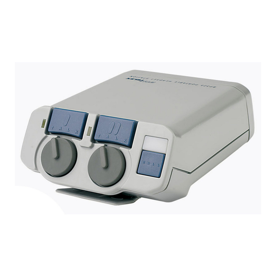
CONNECTIONS AND OPERATION Channel 1 talk button, indicator light and listen volume control. Channel 2 talk button, indicator light and listen volume control. Call button and indicator light. Carbon-mic headset jack. May also be used for external mic switch. See "Programable Options". Program volume control. -
Page 7: Programmable Options
HOST THRU BP-325 Unit Jumper Settings - This equipment complies with the requirements in Part 15 of the FCC Rules for a TABLE 1. Class A computing device. Operation of this equipment in a residential area may cause unacceptable interference to radio and TV reception requiring the operator to take whatever steps are necessary to correct the interference. -
Page 8: Jumpers (W1-W7)
TALK button(s) ON. Release the mic switch to turn the TALK button(s) OFF. Note, the TALK buttons may still be turned ON or OFF from the BP-325; however, the external mic switch will not work unless the TALK buttons are first turned ON at the BP-325... -
Page 9: Sidetone Adjustment
TALK button(s). Release the mic switch to turn off the TALK button(s). Note, the TALK buttons may still be turned ON or OFF from the BP-325; how- ever, the external mic switch will not work unless the TALK buttons are first turned on at the BP- 325. - Page 10 CONNECTIONS AND OPERATION Pin 3, Ch 2 +Audio Pin 2, +18 TO +24 VDC TO BP325 LINE INPUT 200 Ohms 10mF / 50V Pin 1, Common LINE INPUT Connector Wiring for 1-Channel FIGURE 1. Operation with Non-RTS Power Supply TRACE Bottom View of the Main Circuit Board FIGURE 2.
-
Page 11: Method Two: Two Channel Operation With A Non-Rts Power Supply
CONNECTIONS AND OPERATION METHOD TWO: TWO CHANNEL OPERATION WITH A NON-RTS POWER SUPPLY Referring to Figure 1, remove all three screws (10a and 10b) on the back connector panel of the BP325. Remove the rear cover/belt clip assembly. There are two connectors that connect the main circuit board to the front panel circuit board. - Page 12 CONNECTIONS AND OPERATION...
-
Page 13: Chapter 2 - Replacement Parts
WHERE TO OBTAIN PARTS Parts may be obtained directly from RTS at: TELEX/RTS SYSTEMS Attn: Factory Service 8601 East Cornhusker Hwy. Lincoln, NE 68507 U.S.A. REPLACEMENT PARTS CHAPTER 2... -
Page 14: Electrical Parts
REPLACEMENT PARTS MECHANICAL PARTS (Reference AS3233 Drawing) Final Assembly (Refer to AS6738 Drawing for Item No. locations) Item Description Front/ Top Panel Assy Rear Panel Assy Bottom Case with Clip Screw, #4-40 X 3/4” Label, Programming Instr Knob, Program Volume Label, Belt Clip Label, Serial Number Front/Top Panel Assy... - Page 15 REPLACEMENT PARTS Electrical Parts Main Circuit Board Description Capacitor, CM, SM, 10 PF, 50V Capacitor, EL, SM, 1 UF, 50V Capacitor, CM, SM, 0.1 UF, 50V C18 - Capacitor, CM, SM, 10 PF, 50V Capacitor, CM, SM, 10 PF, 50V C22 - Capacitor, EL, SM, 22 UF, 35V Capacitor, CM, SM, 10 PF, 50V...
- Page 16 REPLACEMENT PARTS Electrical Parts Main Circuit Board Description Resistor, SM, 22K Ohm, 5%, 1/8W Resistor, SM, 1K Ohm, 5%, 1/8W Resistor, SM, 301 Ohm, 1%, 1/8W Resistor, SM, 3.01K Ohm, 1%, 1/ Testor, SM, 301 Ohm, 1%, 1/8W Resistor, SM, 3.01K Ohm, 1%, 1/ Resistor, SM, 1K Ohm, 5%, 1/8W Resistor, SM, 620 Ohm, 5%, 1/8W Resistor, SM, 100K Ohm, 5%, 1/...
- Page 17 REPLACEMENT PARTS Electrical Parts Main Circuit Board Description Resistor, SM, 100K Ohm, 5%, 1/ Resistor, SM, 10K Ohm, 5%, 1/8W Resistor, SM, 2.7 Ohm, 5%, 1/8W Resistor, SM, 10K Ohm, 5%, 1/8W Resistor, SM, 1.1K Ohm, 5%, 1/8W Resistor, SM, 30 Ohm, 5%, 1/8W R73 - Resistor, SM, 22K Ohm, 5%, 1/8W Resistor, SM, 200 Ohm, 5%, 1/8W...
- Page 18 REPLACEMENT PARTS Electrical Parts Main Circuit Board Description Connector, St Header, 0.100, M3 Trimpot Shaft Heatsink Screw, 4-40 X 1/4” pan head phillips Nut, 4-40 special, small pattern Washer, 4-40 compression Front Panel Circuit Board Description DS1, LED, Yellow LED, Red J8, J9 Connector, 6-Pin R1, R2...
-
Page 19: Chapter 3 - Specifications And Drawings
Drawing Number 9030-6634-000 9030-6635-000 AS6736 AS6737 AS6738 SD6634 SD6635 Specifications and Drawings Title Front Panel Circuit Board Component Layout Main Circuit Board Component Layout Rear Panel Assembly Front/Top Panel Assembly Final Assembly Schematic Diagram, Front Panel Circuit Board Schematic Diagram, Main Circuit Board CHAPTER 3... -
Page 20: Specifications
Specifications and Drawings Specifications Dimensions 5.00” High x 3.75” Wide x 2.05” Deep (127mm x 96.3mm x 52.1mm) Weight 0.5 pounds (225 grams) Exterior Polystyrene and polycarbonate mix; gray textured main body Power Requirements Input DC Voltage =18 to +35 volts DC, operating; -200 to +36 volts DC without damage DC Current Average talk + call light: 6 No Signal: 27 milliamperes. - Page 30 12000 Portland Avenue South • Burnsville, MN 55337 • U.S.A...