
Related Manuals for Telex RADIOCOM BTR-300B


Summary of Contents for Telex RADIOCOM BTR-300B
- Page 1 Telex Op er ating In struc tions PRO FES SIONAL WIRELESS IN TER COM SYS TEM TR-300, TR-300P, BTR-300, BTR-300B...
-
Page 3: Table Of Contents
TA BLE OF CON TENTS IN TRO DUC TION..........................1 GEN ERAL DE SCRIP TION......................1 BTR-300 BASE STATION TRANS CEIVER ..................3 TECH NI CAL IN FOR MA TION ......................3 SPEC I FI CA TIONS ........................3 FEA TURES..........................4 CON TROLS AND CON NEC TIONS....................5 FRONT PANEL ........................5 REAR PANEL .........................6 TR-300 BELT-PACK TRANS CEIVER...................9... - Page 4 TA BLE OF CON TENTS (CONT.) PRE-WALK-THRU CHECK LIST ....................26 SYS TEM OP ER A TION ........................27 BTR-300 OP ER A TION .........................27 POWER..........................27 LO CAL HEAD SET VOL UME.....................27 PUSH TO TALK/LOCK TO TALK SWITCH..............27 TR-300 OP ER A TION........................28 POWER..........................28 BAT TERY CHECK .......................28 HEAD SET VOL UME ......................28...
-
Page 5: In Tro Duc Tion
- The Telex Models BTR-300 and TR-300 were iary sys tem. The BTR-300 Base Sta tion with spe cif i cally de signed to pro vide the user with a... - Page 6 - num ber of other wired in ter com man u fac tur ers work with one Telex Model BTR-300 Base units. See the BTR-300 Setup Sec tion for ad di - Sta tion.
-
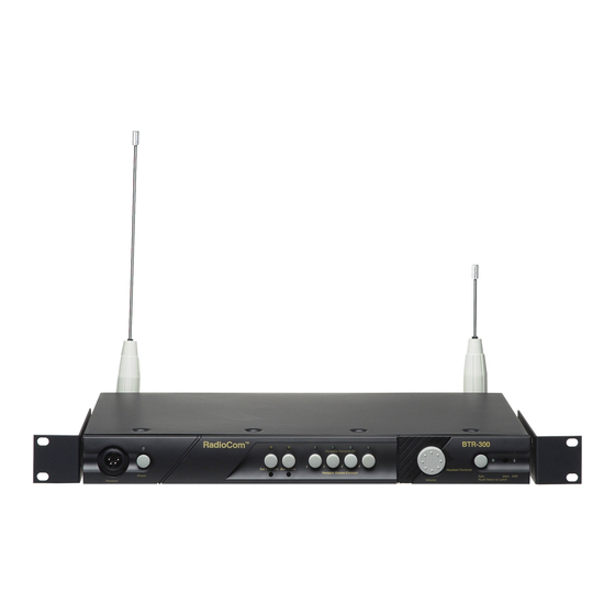
Page 7: Btr-300 Base Station Trans Ceiver
BTR-300 BASE STATION TRANS CEIVER TECH NI CAL IN FOR MA TION SPEC I FI CA TIONS BTR-300 Over all In put Power............... 13.0 VAC RMS/600 mA with sup plied adap tor or fil tered 12 to 14 VDC/600 mA source. In ter com Out put ..50 mV (Low) or 330 mV (Hi) RMS into 300 ohm load typ i cal (at rated de vi a tion) In ter com In put (Gain Min i mum).......... -
Page 8: Spec I Fi Ca Tions
Dis tor tion ..................... Less than 1% at Rated Out put FEA TURES • The Telex Model BTR-300 is a Base Sta tion In ter com con nec tions with the abil ity to in - with one trans mit ter and four re ceiv ers. It is de - ter face with most wired in ter com sys tems. -
Page 9: Con Trols And Con Nec Tions
In put/Out put. The head set jack will Overmodulation In di ca tor: A screw driver ac cept many Telex model head sets. Com pat i ble ad just able con trol is pro vided to con trol the in - with other in ter com head sets with four pin put level of the lo cal head set mic. -
Page 10: Rear Panel
Ext In ter com Switch, Level Con trol, and In - Head set Mi cro phone Se lect Switch:This di ca tor: This switch en ables the wired in ter - switch al lows the user to se lect ei ther an com in ter face when “IN”, and dis ables it when Electret or Dy namic mi cro phone. -
Page 13: Tr-300 Belt-Pack Trans Ceiver
TR-300 BELT-PACK TRANS CEIVER TECH NI CAL IN FOR MA TION SPEC I FI CA TIONS TR-300 Over all Power Re quire ments ..............6 AA cells (Al ka line, NEDA, MN 1500) Nickel Cad mium Op tional Cur rent Drain ........................typ i cal 65 mA Tem per a ture Range .................. -
Page 14: Fea Tures
In put/Out put. The head set jack will ac cept con trol serves as both an off/on switch and as a many dif fer ent Telex model head sets. Com pat i - vol ume con trol. ble with other in ter com head sets with four pin... - Page 15 Fig ure 6 Ex ter nal Con trols, TR-300 -11-...
-
Page 16: In Ter Nal Con Trols
Fig ure 7 In ter nal Con trols, TR-300 IN TER NAL CON TROLS (Re fer To Fig ure 7) Mi cro phone Gain Con trol: Screw driver ad - Dy namic/Electret Switch:This switch al lows just able by re mov ing belt clip and pry ing out se lec tion of “D”when us ing a Dy namic Mi cro - the small rub ber plug to the right of the screw phone or "... -
Page 17: Equip Ment Set-Up
EQUIP MENT SET-UP UN PACKING Un pack your BTR-300 and TR-300 Sys tem. If there are any dam ages or short ages, re fer to the “War ranty Ser vice In for ma tion" sec tion in this man ual. AN TENNA IN FOR MA TION AN TENNA CON NEC TIONS To in sure that the fre quency range of the an ten -... -
Page 18: An Tenna Po Lar Iza Tion
AN TENNA PO LAR IZA TION The Telex Wire less In ter com Sys tem is “Ver ti - cally Po lar ized". This means both the trans mit - ting and re ceiv ing an ten nas should op er ate in the ver ti cal po si tion. -
Page 19: Im Proving Re Cep Tion/In Creasing Range
At tempting to op er ate the wire less in ter com DO NOT- mount the BTR-300 5/8-wave an - sys tem through or around walls, ceil ings, metal ten nas on, or next to, metal such as beams, ob jects, etc. will re duce sys tem range and per - walls with metal studs, equip ment racks, etc. -
Page 20: Btr-300 Set-Up
The switch is fac tory set for in ter fac - the High/Low switch as shown in the next sec - ing with Telex Audiocom wired in ter com tion and then re place cover and se cure with the units. - Page 21 For the cor rect set ting cor re spond ing to your wired in ter com unit see Ta ble 2. The switch is Clearcom fac tory set for use with Telex AudioCom or RTS wired in ter coms. Ta ble 2...
-
Page 22: Rack Mounting
RACK MOUNTING To rack mount the BTR-300 base trans ceiver Place the rack mount brack ets (sup plied) on ei - do the fol low ing: ther side of the unit and in sert three #6-32 x 3/8" screws for each bracket. Tighten the Re move the front two #6-32 x 3/8"... - Page 23 Remoting An tennas: It will be nec es sary to You will also need to re mote the trans mit an - re mote both the trans mit and re ceive an ten nas tenna in the same man ner. Con nect a coax ca - on the BTR-300 when it is rack mounted.
-
Page 24: Lo Cal Head Set Con Nec Tion
(Fig ure 2) if other than a Telex Head set is used. H E A D S E T MI C R O P H O N E SE L E C T... -
Page 25: In Ter Con Nec Tion To A Hard-Wired In Ter Com
The RADIOCOM wire less sys tem can be in te - BTR-300. There are two in ter com con nec tions grated into Telex in ter com sys tems and most on the back of the unit, one be ing a male con -... -
Page 26: Power Con Nec Tion
Fig ure 23 Con necting Two BTR-300’s CONNECTING AUXILIARY AUDIO SYSTEM DUMMY LOAD Connect the BTR-300 to your aux il iary au dio In the case where a wired in ter com will not be via the Aux il iary in put/out put re cep ta cles on used with the BTR-300, it is im por tant that the the rear of the unit. -
Page 27: Tr-300 Set-Up
(Fig ure 5) if headsets other than by re mov ing the belt clip on the back of the Telex are used. unit. Re lease the 1/4 turn fas tener lo cated on the back of the belt clip and re move belt clip/cover. -
Page 28: Pre-Walk-Thru Checklist
PRE-WALK-THRU CHECKLIST Fol low ing the in struc tions fully to this point, Set trans mit switch on BTR-300. you have suc cess fully com pleted the fol low ing check list: Con nected head sets to BTR-300 and all TR-300’s. Set in ter nal in ter com switch to cor re - spond with the wired in ter com. -
Page 29: Sys Tem Op Er A Tion
SYS TEM OP ER A TION BTR-300 OP ER A TION PUSH TALK/LOCK-TO-TALK POWER SWITCH If you have fol lowed the in struc tions un til this To en able the talk func tion on the BTR-300, point, you should now be ready to turn both the press and hold down on the talk but ton and be - TR-300 and the BTR-300 “ON”. -
Page 30: Tr-300 Op Er A Tion
TR-300 OP ER A TION POWER PUSH TO TALK/PUSH TO TRANS MIT You should now be ready to turn the TR-300 To en able the talk func tion on the Model “ON”. Ro tate the OFF/ON Vol ume Con trol TR-300 press and hold down on the talk but ton Switch on the TR-300 clock wise to turn the and be gin talk ing. -
Page 31: Bat Tery Re Moval
The in ter com switch in the front of the unit will act as an en abling switch when the unit is be ing used with ei ther a Telex Audiocom wired in ter - com or Clearcom wired in ter com. -
Page 32: Setting Sys Tem Gain Levels
SETTING SYS TEM GAIN LEVELS AD JUSTING GAIN BTR-300 BASE STATION The gain may need to be ad justed for var i ous The mi cro phone overmodulation in di ca tor for au dio con di tions. The overmodulation LED the BTR-300 head set can be found on the right will in di cate when the gain is too high. -
Page 33: In Ter Com Gain
Now that you have suc cess fully “set up” your The “sys tem walk-thru” can de tect prob lems of TELEX Wire less In ter com Sys tem and turned weak sig nal strength caused by: on any aux il iary equip ment you are ready to •... -
Page 34: Trou Ble Shooting
IN TER FER ENCE - Sys tem picks up sig - Make sure Telex TR-300 beltpack is turned nals other than wire less In ter coms. on - this will usu ally elim i nate the in ter fer ing sig nal. -
Page 35: Bat Tery In For Ma Tion
BAT TERY IN FOR MA TION GEN ERAL Im proper bat tery se lec tion, use, in stal la tion and Nickel-Cadmium Bat teries: These bat ter ies care are the cause of nu mer ous wire less sys tem can save you money in the long run, as they fail ures. -
Page 36: Ac Ces Sories
AC CES SORIES Wall Mount Bracket - For ver ti cal 5/8-wave Ver ti cal 5/8-Wave An tenna - Screw apart for an tenna. easy stor ing. Or der No. 63906-000 For Or der In for ma tion please con tact the Dealer. -
Page 37: War Ranty Ser Vice In For Ma Tion
Telex re serves the right to make changes in de sign and im prove ment on its prod uct with out as sum ing any ob li ga tion to in stall the same on any of its prod ucts pre vi ously man u fac tured. -
Page 38: Fcc In For Ma Tion
The Telex Models BTR-300 and TR-300 transceivers are Type Accepted under United States Federal Communications Commission Parts 90 and 74. Licensing of Telex equipment is the user’s responsibility and licensability depends upon the user’s classification, user’s application, and frequency selected. Telex strongly urges the user to contact the appropriate telecommunications authority for any desired clarification. - Page 39 9600 Aldrich Ave. So., Min ne ap o lis, Min ne sota, 55420 U.S.A. PN 80 SEPT 1999 Made in U.S.A...