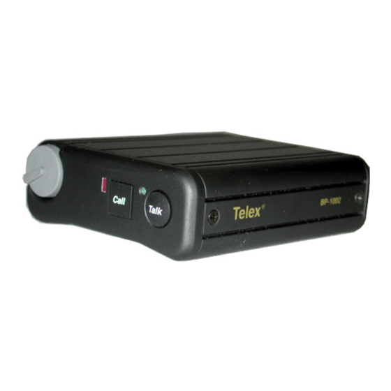
Telex BP-2002 Operating Instructions Manual
Hide thumbs
Also See for BP-2002:
- Operating instructions manual (24 pages) ,
- Operating instructions manual (10 pages) ,
- Operating instructions manual (8 pages)
Summary of Contents for Telex BP-2002
-
Page 1: Operating Instructions
Operating Instructions BP-1002 / BP-2002 Beltpacks Audiocom Intercom Systems 93507740000 Rev L September/2010... - Page 2 Audiocom Intercom Systems ROPRIETARY OTICE The product information and design disclosed herein were originated by and are the property of Bosch Security Systems, Inc. Bosch reserves all patent, proprietary design, manufacturing, reproduction, use and sales rights thereto, and to any article disclosed therein, except to the extent rights are expressly granted to others.
- Page 3 Audiocom Intercom Systems Important Safety Instructions Read these instructions. Keep these instructions. Heed all warnings. Follow all instructions. Do not use this apparatus near water. Clean only with dry cloth. Do not block any ventilation openings. Install in accordance with the manufacturer’s instructions.
- Page 4 Audiocom Intercom Systems...
-
Page 5: Table Of Contents
Table Contents INTRODUCTION ..............3 External Connections and Controls ..........5 OPERATION ................7 System Power .................. 7 Initial BP-1002/2002 Setup ............. 7 Operating Modes ................8 Changing Modes of Operation ............... 8 Internal Switches, Jumpers, and Adjustments ......... 9 Sidetone Adjustment (R145) ..............9 Mic Gain Adjustment (R156) ............... -
Page 7: Introduction
If you have a BP-1002/2002 with a 9030-7740-XXX circuit board, you must obtain revision H of this user manual. The Audiocom BP-1002 and BP-2002 are microprocessor controlled 1- and 2-channel intercom beltpacks. An internal switch and jumper setting allows the units to be used with Clear-Com components, if desired. - Page 8 Introduction BP-2002 & BP-1002 Connections and Controls FIGURE 1.
-
Page 9: External Connections And Controls
Momentary Mode - Press and hold the • button to talk momentarily. Release the button when finished talking. NOTE: On the BP-2002, if no headset is connected, when the Talk button is pressed, the Talk button has the same function as the Chan button. - Page 10 Headset Connector: This connector accepts a 4-wire Bosch boom microphone headset. Intercom Channel Connectors: On the BP-2002, intercom channels are connected via a pair of 6-pin connectors (one male and one female). The male and female connectors are wired together in parallel, providing a loop-through at each connector pin.
-
Page 11: Operation
The local power (pin 2) of the intercom channel connector • (BP-2002 only) Both the BP-1002 and BP-2002 pass system power through to subsequent beltpacks that are daisy chained together. Initial BP-1002/2002 Setup The channel termination is initially set for balanced operation, which is compatible with other Audiocom equipment. -
Page 12: Operating Modes
Operation Operating Modes The microprocessor within the BP-1002/2002 controls four (4) modes of operation that affect the Microphone Kill and Audible Call Alert features. These modes can be seen in Table X on page X. Changing Modes of Operation Perform the following steps to change the mode of operation. NOTE: Both the Talk and Call indicators should be off and the headset should be connected. -
Page 13: Internal Switches, Jumpers, And Adjustments
FIGURE 2. NOTE: Figure 2 shows a BP-2002 with the switches and jumpers in their factory default positions. SW5 does not exist on the BP-1002 board. The Sidetone and Mic Gain adjustment are also accessible behind the screw that holds the belt clip (callout 5 in Figure 1). -
Page 14: Mic Gain Adjustment (R156)
Operation To adjust the level of your own voice heard in the headphones, tap the Talk button once to turn on the headset microphone. Then, use a small Phillips head screwdriver to increase or decrease your voice level while talking into the microphone. Mic Gain Adjustment (R156) The Mic Gain Adjustment is accessible internally on the board (R156) (refer to Figure 3) or by removing the belt clip mounting screw (callout 5 in Figure 1). -
Page 15: Connector Pin Configurations
Pin 1 Common Pin 2 +30VDC input Pin 3 Intercom audio/call signal BP-2002 Type: One XLR-6M and XLR-6F pair (callout 7 in Figure 1) Audiocom Mode (internal switch SW1 set to BAL position) Pin 1 Common Pin 2 Local Power (21-30VDC) -
Page 16: Specifications
Operation Specifications General Power Requirements: Channel Supplied: 24VDC nominal, 40 to 100mA Local Power: 24VDC nominal (21 to 30VDC), 40 to 100mA Environmental Requirements: Storage: -20°C to 80°C; 0% to 95% humidity, non-condensing Operating: -15°C to 60°C; 0% to 95% humidity, non-condensing Dimensions: 5.0”... -
Page 17: Optional Football Modifications
Operation Headphone Amplifier Maximum Output: 3.5 ±10% Vrms into 150Ω headset Frequency Response: 200Hz to 8kHz ±2dB Audible Alert: 1kHz, at the headset Total Harmonic Distortion: Less than 1% at less than 3.25V into 150Ω headset Sidetone: 17dB minimum range, adjustable Optional Football Modifications General Description In Audiocom Intercom Systems, the Mic Kill feature is used to turn off any activated... - Page 18 Operation To restore the Mic Kill and Call Signal feature, replace C61 with Bosch part number F01U143777, 1500pF, 50V capacitor. Printed Circuit Board FIGURE 3.
-
Page 19: Notes
Operation Notes...


