Telex Audiocom BP-2002 Operating Instructions Manual
Belt packs audiocom intercom system
Hide thumbs
Also See for Audiocom BP-2002:
- Operating instructions manual (20 pages) ,
- Operating instructions manual (10 pages) ,
- Operating instructions manual (19 pages)

Related Manuals for Telex Audiocom BP-2002


Summary of Contents for Telex Audiocom BP-2002
-
Page 1: Operating Instructions
Telex Operating Instructions BP-1002/BP-2002 Belt Packs ® Audiocom Intercom System 93507740-000 Rev E 10/2003... -
Page 3: Fcc Statement
(at his own ex- pense) will be required to correct. This product meets the Electromagnetic Compatibility Directive, 89/336/EEC. ® Audiocom is a registered trademark of Telex Communications, Inc., Burnsville, Minnesota 55337 ® Clear-Com is a registered trademark of Clear-Com Intercom Systems... - Page 4 End-User License Agreement for Telex ® Software IMPORTANT - Please read this document carefully before using this product. THIS DOCUMENT STATES THE TERMS AND CONDITIONS UPON WHICH TELEX COMMUNICATIONS, INC. ( ‘COMPANY’) OFFERS TO LICENSE THE INSTALLED SOFTWARE OR PROGRAM ( ‘SOFT-...
-
Page 5: Operation
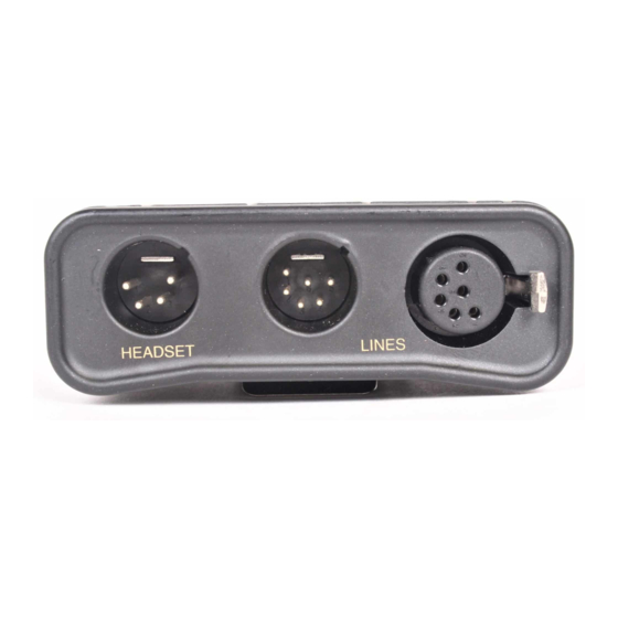
OPERATION SYSTEM POWER The BP-2002 belt pack receives power externally, in one of two ways: • Via the intercom channel. • Via the local-power (pin 2) of the intercom channel connector The BP-1002 belt pack receives power externally, via the intercom channel. - Page 6 Figure 1. BP-2002 & BP-1002 Connections and Controls...
-
Page 7: External Connections & Controls
EXTERNAL CONNECTIONS & CONTROLS NOTE: The numbers refer to the callouts in Figure 1. 1. V : Use this control to adjust the OLUME ONTROL headset listen level. : The Chan button (only UTTON AND NDICATORS on the BP-2002) allows the user to select which intercom channel is active. - Page 8 6. H : This connector accepts a four- EADSET ONNECTOR wire Telex® boom-microphone headset. 7. I : On the BP-2002, NTERCOM HANNEL ONNECTORS intercom channels are connected via a pair of 6-pin connectors (one male and one female).
-
Page 9: Operating Modes
Local Power Input (BP-2002 only) Normally the BP-2002 is powered from the intercom system and will turn on with the intercom system. The BP-2002 belt pack may also be powered from an optional power supply (18-30 VDC) connected be- tween pin 2 (+) and pin 1 (-) of the intercom channel connector. - Page 10 Changing Modes of Operation: Perform the following steps to change the mode of operation. Both the Talk and Call indicators should be off. Press and hold the Talk key, then press and hold the Call key, then release both keys. The Call indicator should now glow red.
-
Page 11: Internal Switches, Jumpers And Adjustments
INTERNAL SWITCHES, JUMPERS AND ADJUSTMENTS There are several internal switches, jumpers and an adjustment that affect operation. These are described below. To gain access to the switches, jumpers and the adjustment, disconnect all power and line connections. Remove two screws from the top of each side and two screws from bottom of each side. - Page 12 NOTE: On the BP-1002, jumper JP6 must always have pins 2 and 3 shorted. Side Tone Adjustment (R145) The side tone adjustment is accessible either internally (refer to Figure 2) or by removing the belt clip mounting screw (callout 5 in Figure 1). To adjust the level of your own voice heard in the headphones, tap the Talk button once to turn on the headset microphone.
- Page 13 Table 3. Internal Switches and Jumpers & & & & & & & & & & & ® ® ® & , y l ® & , y l ® & ™...
-
Page 14: Connector Pin Configurations
Note: In case of local power use, install a jumper on pins 2 & 3 of U6 CONNECTOR PIN CONFIGURATIONS Headset Connector Type: XLR-4M (callout 6 in Figure 1) Pin 1 Headset microphone low Pin 2 Headset microphone high Pin 3 Headphone high Pin 4 Headphone low... - Page 15 BP-2002 Type: One XLR-6M and XLR-6F pair (callout 7 in Figure 1) ® Audiocom Mode (Internal switch SW1 and jumpers JP4, JP5, JP2 and JP1 set to BAL position) Pin 1 Common Pin 2 Local power (+24 VDC) Pin 3 Channel A intercom audio low and +24 VDC input Pin 4 Channel A intercom audio high and +24 VDC input...
-
Page 16: Specifications
SPECIFICATIONS GENERAL: Power Requirements: Channel supplied: 24 VDC nominal, 45 to 70 mA Local-power: (BP-2000 only) 24 VDC nominal (18 to 30 VDC), 45 to 70 mA Environmental Requirements: Storage: -20ºC to 80ºC; 0% to 95% humidity, non-condensing Operating: -15ºC to 60ºC; 0% to 95% humidity, non-condensing Dimensions: 5.0"... -
Page 17: Headphone Amplifier
Unbalanced Intercom Channel: Output Level: 480 mVrms ±10% Input Impedance: 200 ohm ±5% Bridging Impedance: greater than 10,000 ohm Call Signalling: Send: 12 ±3 VDC Receive: 4 VDC minimum HEADPHONE AMPLIFIER: Voltage Gain: 20 ±3 dB from the line Maximum Output: 60 mW into 150 ohm Frequency Response: 200 Hz to 8 kHz with no more than 4 dB deviation... - Page 18 DYNAMIC MICROPHONE AMPLIFIER: Voltage Gain: Mic to Channel; 45 ±3 dB, before limiting Mic to Headphone; adjustable, 65 dB range into 150 Frequency Response: 200 Hz to 8 kHz +1/-3dB Total Harmonic Distortion: Less than 1% at Channel output at 1 kHz ELECTRET MICROPHONE AMPLIFIER: Voltage Gain: Mic to Channel;...
- Page 19 Figure 4. Board Number 9040-7740-000. : y l : y l Default Settings...
-
Page 20: Optional Football Modifications
Refer to Figure 3 and locate C61 on the underside of the printed circuit board. Remove capacitor C61 from the printed circuit board. RESTORING MIC-KILL AND CALL SIGNAL ® To restore the Mic-Kill and Call signal features, replace C61 with Telex part number 102879-218, 1500 pF, 50V capacitor. - Page 21 Figure 3. Printed Circuit Board...
-
Page 22: Factory Service
- Equipment that is not under warranty must be sent ARRANTY EPAIRS prepaid to Telex. If requested, an estimate of repair costs will be issued prior to service. Once your approval for repair, and repair of equipment is completed, the equipment will be returned on a collect basis. Collect...