Table of Contents
Advertisement
Quick Links
Advertisement
Table of Contents

Related Manuals for Supermicro X7DWA-N


Summary of Contents for Supermicro X7DWA-N
- Page 1 UPER X7DWA-N USER’S MANUAL Revision 1.1b...
- Page 2 Please Note: For the most up-to-date version of this manual, please see our web site at www.supermicro.com. Super Micro Computer, Inc. ("Supermicro") reserves the right to make changes to the product described in this manual at any time and without notice. This product, including software, if any, and documentation may not, in whole or in part, be copied, photocopied, reproduced, translated or reduced to any medium or machine without prior written consent.
-
Page 3: Manual Organization
Core Microarchitecture, Intel Virtualization Technology, Intel Extended Memory 64 Technology (EM64), and Intel I/O Acceleration Technology (Intel I/OAT). The X7DWA-N offers a superb solution for intense computing and complex I/O envi- ronments, and is ideal to be integrated into high-end workstations. Please refer to the motherboard specifi... -
Page 4: Table Of Contents
Conventions Used in the Manual ... iii Chapter 1: Introduction Overview ... 1-1 Checklist ... 1-1 Contacting Supermicro ... 1-2 X7DWA-N Image ... 1-3 X7DWA-N Layout ... 1-4 Quick Reference ... 1-5 Motherboard Features ... 1-6 Intel 5400 Chipset: System Block Diagram ... 1-8 Chipset Overview ... - Page 5 2-6 Connecting Cables ... 2-14 ATX Power Connector ... 2-14 Processor Power Connector ... 2-14 Universal Serial Bus (USB) ... 2-15 Chassis Intrusion ... 2-15 Fan Headers ... 2-16 ATX PS/2 Keyboard and Mouse Ports ...2-17 Serial Ports ... 2-17 Wake-On-Ring ...2-18 Wake-On-LAN ...2-18 GLAN 1/2 (Ethernet) Ports ...2-19...
- Page 6 X7DWA-N User's Manual Chapter 3: Troubleshooting Troubleshooting Procedures ... 3-1 Before Power On ... 3-1 No Power ... 3-1 No Video ... 3-1 Losing the System’s Setup Confi guration ... 3-2 Memory Errors ... 3-2 Technical Support Procedures ... 3-2 Frequently Asked Questions ...
-
Page 7: Chapter 1: Introduction
Checklist Congratulations on purchasing your computer motherboard from an acknowledged leader in the industry. Supermicro boards are designed with the utmost attention to detail to provide you with the highest standards in quality and performance. Check that the following items have all been included with your motherboard. If anything listed here is damaged or missing, contact your retailer. -
Page 8: Contacting Supermicro
X7DWA-N User's Manual Contacting Supermicro Headquarters Address: Super Micro Computer, Inc. 980 Rock Ave. San Jose, CA 95131 U.S.A. Tel: +1 (408) 503-8000 Fax: +1 (408) 503-8008 Email: marketing@supermicro.com (General Information) support@supermicro.com (Technical Support) Web Site: www.supermicro.com Europe Address: Super Micro Computer B.V. -
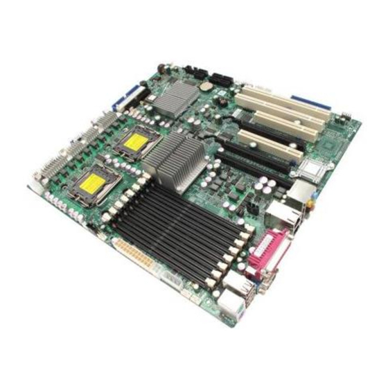
Page 9: X7Dwa-N Image
Chapter 1: Introduction X7DWA-N Image Note: The drawings and pictures shown in this manual were based on the latest PCB Revision available at the time of publishing of the manual. The motherboard you’ve received may or may not look exactly the same as the... -
Page 10: X7Dwa-N Layout
4. JIDE2 is for Compact Flash Card use only. Be sure to connect JWF1 to a power supply to provide power to the Compact Flash Card. 5. Slot 0 (PCI-U) slot is specially designed for Supermicro's UIO cards only. Fan 1... -
Page 11: Quick Reference
Quick Reference (X7DWA-N) Jumper Description 3rd PWR Failure Detect JBT1 CMOS Clear JCF1 Compact Card Master/Slave Select C1/JI SMB to PCI-X Slots C3/JI SMB to PCI-E Slots JPL1 GLAN1/GLAN2 Enable Watch Dog Connector Description 1394-1/1394-2 1394-1/1394-2 Fire-Wire Connectors CD-In Header... -
Page 12: Motherboard Features
• Two PCI-X 133/100 MHz Slot (Slot 1/Slot 2) • Two PCI-33 MHz (3.3 V) slots (Slot 3/Slot 5) • One IPMI slot (Slot 7) • One PCI-U slot (Slot 0) (For Supermicro's UIO card only) BIOS • 8 Mb Phoenix ®... - Page 13 Chapter 1: Introduction • System resource alert ACPI Features • Slow blinking LED for suspend state indicator • Main switch override mechanism Onboard I/O • Adaptec Host RAID support (RAID 0, RAID1, RAID 10) • One IPMI slot • Intel 82575EB Gigabit Ethernet controllers support two GLAN ports w/IOAT •...
- Page 14 X7DWA-N User's Manual PROCESSOR#2 ISL6307 1600/1333/1066 MT/s PCI-E x16 PCI-E x16 RJ45 Port PCI-E x4 GB LAN RJ45 Ports PCI-E x8 #1,2 PCI-X 133MHz PCI 33MHz 1U-IPMI 7.1 channel Parallel Port Block Diagram of the 5400 Chipset Note: This is a general block diagram. Please see the previous Motherboard Features pages for details on the features of the motherboard.
-
Page 15: Chipset Overview
Combined with the functionality offered by the onboard LAN controller, the ESB2 also supports alert systems for remote management. With the 5400 chipset built in, the X7DWA-N offers a superb solution for intense computing and complex I/O environments, and is ideal for high-end server sys-... -
Page 16: Special Features
Control setting in the Advanced BIOS Setup section to change the setting. The default setting is Last State. PC Health Monitoring This section describes the PC health monitoring features of the X7DWA-N. All have an onboard System Hardware Monitor chip that supports PC health moni- toring. -
Page 17: Acpi Features
low on virtual memory and there is insuffi cient hard drive space for saving the data, you can be alerted of the potential problem. You can also confi gure Supero Doctor to provide you with warnings when the system temperature goes beyond a pre-defi... -
Page 18: Power Supply
It is even more important for processors that have high CPU clock rates. The X7DWA-N can only accommodate 24-pin ATX power supplies. Although most power supplies generally meet the specifi cations required by the CPU, some are inadequate. You should use one that will supply at least 500W of power. In addition, the 12V 4-pin power and the 12V 8-pin are also required for adequate power supply to the system. - Page 19 Chapter 1: Introduction an advanced speed with baud rates of 250 K, 500 K, or 1 Mb/s, which support higher speed modems. The Super I/O supports one PC-compatible printer port (SPP), Bi-directional Printer Port (BPP), Enhanced Parallel Port (EPP) or Extended Capabilities Port (ECP).
- Page 20 X7DWA-N User's Manual Notes 1-14...
-
Page 21: Chapter 2: Installation
Note: Be sure to mount the motherboard into the chassis before you install the CPU onto the motherboard. All motherboards have standard mounting holes to fi t different types of chassis. Make sure that the locations of all the mounting holes for both motherboard and chassis match. -
Page 22: Processor And Heatsink Installation
X7DWA-N User's Manual Processor and Heatsink Installation When handling the processor package, avoid placing direct pressure on the label area of the fan. Notes: Always connect the power cord last and always remove it before adding, removing or changing any hardware components. Make sure that you install the processor into the CPU socket before you install the CPU heatsink. - Page 23 Installing the LGA771 Processor Press the load lever to release the load plate, which covers the CPU socket, from its locking position. Gently lift the load lever to open the load plate. Use your thumb and your index finger to hold the CPU at the North Center Edge and the South Center Edge of the CPU.
- Page 24 X7DWA-N User's Manual Loading the CPU into the Socket Align CPU Pin1 (the CPU corner marked with a triangle) against the socket corner that is marked with a triangle cutout. Align the CPU key that is the semi-circle cutout below a gold...
- Page 25 Installation and Removal of the Heatsink Do not apply any thermal grease to the heatsink or the CPU die-the required amount has already been applied. Place the heatsink on top of the CPU so that the four mounting holes are aligned with those on the retention mechanism.
-
Page 26: Installing Dimms
Repeat for all modules (see step 1 above). Memory Support The X7DWA-N supports up to 64 GB fully buffered (FBD) ECC DDR2 800/667/533 in 8 DIMMs. Populating DIMM modules with a pair (or pairs) of memory modules of the same type and same size will result in interleaved memory. For best per- formance, please install (a) pair(s) of DIMM modules of the same type in both Branch 0 and Branch 1. - Page 27 Note 2: DDR2 FBD 800 MHz memory is supported by the processors with FSB 1333 MHz and 1066 MHz; however, it will run @667 MHz. Note 3: Due to the OS limitations, some operating systems may not show more than 4 GB of memory. Note 4: Due to memory allocation to system devices, memory remaining avail- able for operational use will be reduced when 4 GB of RAM is used.
-
Page 28: Control Panel Connectors And Io Ports
X7DWA-N User's Manual Control Panel Connectors/IO Ports The I/O ports are color coded in conformance with the PC 99 specifi cation. See Figure 2-3 below for the colors and locations of the various I/O ports. Back Panel Connectors/IO Ports Back Panel I/O Port Locations and Defi nitions Back Panel Connectors 1. -
Page 29: Front Control Panel
These connectors are de- signed specifi cally for use with Supermicro server chassis. See Figure 2-4 for the descriptions of the various control panel buttons and LED indicators. Refer to the following section for descriptions and pin defi... -
Page 30: Front Control Panel Pin Defi Nitions
X7DWA-N User's Manual Front Control Panel Pin Defi nitions NMI Button The non-maskable interrupt button header is located on pins 19 and 20 of JF1. Refer to the table on the right for pin defi nitions. Power LED The Power LED connection is located on pins 15 and 16 of JF1. -
Page 31: Hdd Led
HDD LED The HDD LED connection is located on pins 13 and 14 of JF1. Attach the hard drive LED cable here to display disk activity (for any hard drives on the system, including Serial ATA and IDE). See the table on the right for pin defi... -
Page 32: Overheat/Fan Fail Led
X7DWA-N User's Manual Overheat/Fan Fail LED (OH) Connect an LED to the OH/Fan Fail connection on pins 7 and 8 of JF1 to provide advanced warnings of chassis overheating or fan failure. Refer to the table on the right for pin defi... -
Page 33: Reset Button
Reset Button The Reset Button connection is located on pins 3 and 4 of JF1. Attach it to the hardware reset switch on the computer case. Refer to the table on the right for pin defi nitions. Power Button The Power Button connection is located on pins 1 and 2 of JF1. -
Page 34: Connecting Cables
X7DWA-N User's Manual Connecting Cables ATX Main PWR & CPU PWR Connectors The 24-pin main power connector (JPW1) is used to provide power to the motherboard. The 8-pin CPU PWR connector (JPW3) is also required for the processors. These power connectors meet the SSI EPS 12V specifi... -
Page 35: Universal Serial Bus (Usb)
Universal Serial Bus (USB) There are six USB 2.0 (Universal Se- rial Bus) ports/headers on the moth- erboard. Four Back Panel USB ports (USB #0, #1, #2 & #3) are located at JUSB1, and the other two are Front Panel Accessible USB headers (USB #4 &... -
Page 36: Fan Headers
X7DWA-N User's Manual Fan Headers The X7DWA-N has eight chassis/ system fan headers (Fan1 to Fan8), including two CPU Fans (Fans 7/8). See the table on the right for pin defi ni- tions. The onboard fans are controlled by Thermal Management via BIOS... -
Page 37: Serial Ports
ATX PS/2 Keyboard and PS/2 Mouse Ports The ATX PS/2 keyboard and the PS/2 mouse are located at JKM1. See the table on the right for pin defi nitions. (The mouse port is above the key- board port. See the table on the right for pin defi... -
Page 38: Wake-On-Ring
X7DWA-N User's Manual Wake-On-Ring The Wake-On-Ring header is des- ignated JWOR. This function allows your computer to receive and be "awakened" by an incoming call to the modem when the system is in the suspend state. See the table on the right for pin defi... -
Page 39: Ethernet Ports
GLAN 1/2 (Giga-bit Ethernet Ports) Two G-bit Ethernet ports are located at JLAN1 on the IO backplane. This port accepts RJ45 type cables. Power LED/Speaker On the JD1 header, pins 1-3 are for a power LED and pins 4-7 are for the speaker. -
Page 40: Power Fault
X7DWA-N User's Manual Power Supply Failure Connect a cable from your power supply to the PSF(Power Supply Failure) header at JP3 to provide a warning of power supply failure. This warning signal is passed through the PWR_LED pin to indicate of a power failure on the chassis. -
Page 41: Alarm Reset
Alarm Reset If three power supplies are installed and Alarm Reset (JAR) is enabled, the system will notify you when any of the three power modules fails. Connect JAR to a micro-switch to enable you to turn off the alarm that is activated when a power module fails. -
Page 42: Compact Flash Card Pwr Connector
X7DWA-N User's Manual Compact Flash Card PWR Connector A Compact Flash Card Power Connector is located at JWF1. For the Compact Flash Card to work properly, you will also need to confi gure JCF1 properly and connect the Compact Flash Card power cable to JWF1 fi... -
Page 43: Hd Audio
High Defi nition Audio (HD Audio) The X7DWA-N features a 7.1+2 Channel High Defi nition Audio (HDA) (JC1) codecs that provides 10DAC channels, simultaneously supporting 7.1 sound playback with 2 channels of independent stereo sound output (multiple streaming) through the front panel stereo out (for front L&R, rear L&R), center and subwoofer speakers. -
Page 44: Front Panel Audio Control
X7DWA-N User's Manual Front Panel Audio Control When front panel headphones are plugged in, the back panel audio output is disabled. This is done through the FP Audio header (JC2). If the front panel interface card is not connected to the front panel audio... -
Page 45: 1394-1/1394-2 Connections
1394-1/1394-2 Connections 1394-1 and 1394-2 provide the IEEE 1394 Fire-Wire connections on the motherboard. See the tables on the right for pin defi nitions. Fan 1 LAN1/2 Audio IPMI PCI-Exp x16 PCI-33MHz IPMB 1394-1 Pin Defi nitions Pin# Defi n. PTPA0+ PTPB0+ PWR 1394... -
Page 46: Jumper Settings
X7DWA-N User's Manual Jumper Settings Explanation of Jumpers To m o di f y t he o p er at i o n of t he motherboard, jumpers can be used to choose between optional settings. Jumpers create shorts between two pins to change the function of the connector. -
Page 47: Cmos Clear
CMOS Clear JBT1 is used to clear CMOS. Instead of pins, this "jumper" consists of contact pads to prevent accidental clearing of CMOS. To clear CMOS, use a metal object such as a small screwdriver to touch both pads at the same time to short the connection. Always remove the AC power cord from the system before clearing CMOS. -
Page 48: 3Rd Pwr Supply Pwr Fault
X7DWA-N User's Manual 3rd PWR Supply PWR Fault Detect (J3P) The system can notify you in the event of a power supply failure. This feature is available when three power supply units are installed in the chassis with one act- ing as a backup. -
Page 49: Compact Flash Master/Slave Enable/Disable
Compact Flash Master/Slave Select A Compact Flash Master/Slave Select Jumper is located at JCF1. Close this jumper to enable Compact Flash Card. For the Compact Flash Card or the Compact Flash Jumper (JCF1) to work properly, you will need to connect the Compact Flash Card power cable to JWF1 fi... -
Page 50: Onboard Indicators
X7DWA-N User's Manual Onboard Indicators GLAN LEDs There are two GLAN ports on the moth- erboard. Each Gigabit Ethernet LAN port has two LEDs. The green LED indicates activity, while the Link LED may be green, amber or off to indicate the speed of the connection. -
Page 51: Overheat Led
Overheat LED (JOH1) The JOH1 header is used to connect an LED to provide warnings in the event of chassis overheating. Refer to the layout below for the location. Also See the table on the right for pin defi nitions. Onboard Power LED (LE1) There is an Onboard Power LED (LE1) located on the motherboard. -
Page 52: Parallel Port Connector
X7DWA-N User's Manual Parallel Port, Floppy Drive, Hard Disk Drive, PCI-U Slot and IPMI Connections Note the following when connecting the fl oppy and hard disk drive cables: • The fl oppy disk drive cable has seven twisted wires. • A red mark on a wire typically designates the location of pin 1. -
Page 53: Floppy Connector
Floppy Connector The fl oppy connector is located at J22. See the table below for pin defi nitions. Fan 1 LAN1/2 Audio IPMI PCI-Exp x16 PCI-33MHz IPMB Floppy Drive Connector Pin Defi nitions (Floppy) Pin# Defi nition Ground Ground Ground Ground Ground Ground... -
Page 54: Ipmi Slot
Slot location. PCI-U Universal Slot PCI-U Slot, located on PCI-Slot 0 (J31), is a PCI-E x8 connector spe- cially designed for Supermicro's stor- age devices to add SATA/SAS and LAN connections to the motherboard. This slot can also support other com- patible PCI-E devices. -
Page 55: Ide Connectors
IDE Connectors There are two IDE Connectors (JIDE1: Blue, JIDE2: White) on the motherboard. The blue IDE connector (JIDE1) is designated the Primary IDE Drive. The white IDE connector (JIDE2) is desig- nated the Secondary IDE Drive, reserved for Compact Flash Card use only. - Page 56 X7DWA-N User's Manual Notes 2-36...
-
Page 57: Chapter 3: Troubleshooting
Troubleshooting Troubleshooting Procedures Use the following procedures to troubleshoot your system. If you have followed all of the procedures below and still need assistance, refer to the ‘Technical Sup- port Procedures’ and/or ‘Returning Merchandise for Service’ section(s) in this chapter. Note: Always disconnect the power cord before adding, changing or install- ing any hardware components. -
Page 58: Losing The System's Setup Confi Guration
X7DWA-N User's Manual Losing the System’s Setup Confi guration 1. Make that you are using a high quality power supply. A poor quality power supply may cause the system to lose the CMOS setup information. Refer to Section 1-6 for details on recommended power supplies. -
Page 59: Frequently Asked Questions
Question: What are the various types of memory that my motherboard can support? Answer: The X7DWA-N has eight 240-pin DIMM slots that support DDR2 FBD ECC 800/667/533 SDRAM modules. It is strongly recommended that you do not mix memory modules of different speeds and sizes. -
Page 60: Returning Merchandise For Service
X7DWA-N User's Manual may take a few minutes to complete. Do not be concerned if the screen is paused for a few minutes. Warning : Do not shut down or reset the system while updating BIOS to prevent possible system boot failure! -
Page 61: Chapter 4: Bios
Introduction This chapter describes the Phoenix BIOS™ Setup utility for the X7DWA-N. The Phoenix ROM BIOS is stored in a fl ash chip and can be easily upgraded using a fl oppy disk-based program. Note: Due to periodic changes to the BIOS, some settings may have been added or deleted and might not yet be recorded in this manual. -
Page 62: Running Setup
X7DWA-N User's Manual Running Setup Default settings are in bold text unless otherwise Noted. The BIOS setup options described in this section are selected by choosing the appropriate text from the main BIOS Setup screen. All displayed text is described in this section although the screen display is often all you need to understand how to set the options as shown on the following page. -
Page 63: Main Bios Setup Menu
Chapter 4: BIOS Main BIOS Setup Menu Main Setup Features System Time To set the system date and time, key in the correct information in the appropriate fi elds. Then press the <Enter> key to save the data. System Date Using the arrow keys, highlight the month, day and year fi... - Page 64 X7DWA-N User's Manual IDE Channel 0 Master/Slave, IDE Channel 1 Master/Slave, SATA Port 3 and SATA Port 4 These settings allow the user to set the parameters of IDE Channel 0 Master/Slave, IDE Channel 1 Master/Slave, SATA Port 3 , SATA Port 4 slots. Hit <Enter> to activate the following sub-menu screen for detailed options of these items.
- Page 65 LBA Format The following items will be displayed by the BIOS: Total Sectors: This item displays the number of total sectors available in the LBA Format. Maximum Capacity: This item displays the maximum capacity in the LBA Format. Multi-Sector Transfers This item allows the user to specify the number of sectors per block to be used in multi-sector transfer.
- Page 66 X7DWA-N User's Manual SATA Controller Mode Option Select Compatible to allow the SATA and PATA drives to be automatically-detected and be placed in the Legacy Mode by the BIOS. Select Enhanced to allow the SATA and PATA drives to be to be automatically-detected and be placed in the Native IDE Mode.
-
Page 67: Advanced Setup
Advanced Setup Choose Advanced from the Phoenix BIOS Setup Utility main menu with the arrow keys. You should see the following display. The items with a triangle beside them have sub menus that can be accessed by highlighting the item and pressing <Enter>. Boot Features Access the submenu to make changes to the following settings. - Page 68 X7DWA-N User's Manual ACPI Sleep Mode This feature allows you to decide which ACPI (Advanced Confi guration and Power Interface) power management mode to use when in the sleep mode. The options are S1, S3 and S1S3. Power Button Behavior If set to Instant-Off, the system will power off immediately as soon as the user hits the power button.
- Page 69 Chapter 4: BIOS Memory Cache Cache System BIOS Area This setting allows you to designate a reserve area in the system memory to be used as a System BIOS buffer to allow the BIOS to write (cache) data into this reserved memory area.
- Page 70 X7DWA-N User's Manual Uncached to disable this function. Select Write Through to allow data to be cached into the buffer and written into the system memory at the same time. Select Write Protect to prevent data from being written into the extended memory area above 1 MB.
- Page 71 Reset Confi guration Data If set to Yes, this setting clears the Extended System Confi guration Data- (ESCD) area. The options are Yes and No. Frequency for PCI-X#1~PCI-X#2 This option allows the user to change the bus frequency for the devices installed in the slot indicated.
- Page 72 X7DWA-N User's Manual SERR Signal Condition This setting specifi es the ECC Error conditions that an SERR# is to be asserted. The options are None, Single Bit, Multiple Bit, and Both. Clock Spectrum Feature If Enabled, the BIOS will enable the Clock Spectrum feature in the Clock Generator.
- Page 73 Chapter 4: BIOS Branch 0 Rank Interleaving/Branch 1 Rank Interleaving Select enable to enable Interleaved Memory for Memory Branch 0 Rank or Branch 1 Rank. The options for Memory Interleaving are 1:1, 2:1 and 4:1. Enhanced x8 Detection Select Enabled to enable Enhanced x8 DRAM UC Error Detection. The options are Disabled and Enabled.
- Page 74 X7DWA-N User's Manual Reserved Branch for ITK Test This feature allows the user to specify the memory branch number to be reserved for ITK testing. The default setting is Branch 1. Snoop Filter Select Enabled to eliminate snoop traffi c to the graphics port to greatly improve system performance when running graphics intensive applications.
- Page 75 Chapter 4: BIOS Fast String Operations (Available if supported by the CPU.) Set to Enabled to enable the fast string operations for special CPU instructions. The options are Disabled and Enabled. Thermal Management 2 (Available if supported by the CPU.) Set to Enabled to use Thermal Management 2 (TM2) which will lower CPU voltage and frequency when the CPU temperature reaches a predefi...
- Page 76 X7DWA-N User's Manual DCA Delay Clocks (Available if supported by the CPU.) This feature allows the user to set the clock delay setting from snoop to prefetch for Direct Cache Access. Select a setting from 8 (bus cycles) to 120 (bus cycles) (in 8-cycle increment).
- Page 77 Chapter 4: BIOS KBC Clock Input This setting allows you to select clock frequency for KBC. The options are 6MHz, 8MHz, 12MHz, and 16MHz. Serial Port A This setting allows you to determine how Serial Port A is controlled. The options are Enabled (user defi...
- Page 78 X7DWA-N User's Manual Mode This feature allows you to specify Parallel Port mode. The options are Output only, Bi-Directional, EPP and ECP. DMA Channel This item allows you to specify the DMA channel for the parallel port. The options are DMA1 and DMA3.
- Page 79 Chapter 4: BIOS Console Redirection Access the submenu to make changes to the following settings. COM Port Address This item allows you to specify which COM port to direct the remote console to: Onboard COM A or Onboard COM B. This setting can also be Disabled. BAUD Rate This item allows you to set the BAUD rate for console redirection.
- Page 80 X7DWA-N User's Manual Hardware Monitor Logic CPU Temperature Threshold This feature displays a predefi ned CPU overheating temperature threshold that will activate the alarm when the CPU temperature reaches this overheat threshold. The options are 70 C, 75 C, 80 C and 85 Highlight this and hit <Enter>...
- Page 81 IPMI (The option is available only when an IPMI card is installed in the system.) IPMI Specifi cation Version: Firmware Version: This item displays the current Firmware Version. System Event Logging Select Enabled to enable IPMI Event Logging. When this function is set to Disabled, the system will continue to log events received via system interface.
- Page 82 X7DWA-N User's Manual OS Boot Watch Dog Set to Enabled to enable OS Boot Watch Dog. The options are Enabled and Disabled. Timer for Loading OS (Minutes) This feature allows the user to set the time value (in minutes) for the previous item: OS Boot Watch Dog by keying-in a desired number in the blank.
- Page 83 Chapter 4: BIOS Realtime Sensor Data This feature display information from motherboard sensors, such as temperatures, fan speeds and voltages of various components. 4-23...
- Page 84 X7DWA-N User's Manual IPMI LAN Confi guration The following features allow the user to confi gure and monitor IPMI LAN settings. VLAN Tagging Select Enabled to enable Virtual LAN(s) for IPMI connections and allow the user to confi gure VLAN settings. The options are Enabled and Disabled.
- Page 85 Chapter 4: BIOS Security Choose Security from the Phoenix BIOS Setup Utility main menu with the arrow keys. You should see the following display. Security setting options are displayed by highlighting the setting using the arrow keys and pressing <Enter>. All Security BIOS settings are described in this section.
- Page 86 X7DWA-N User's Manual Password on Boot This setting allows you to determine if a password is required for a user to enter the system at system boot. The options are Enabled (password required) and Disabled (password not required). Boot Choose Boot from the Phoenix BIOS Setup Utility main menu with the arrow keys.
-
Page 87: Exit
Chapter 4: BIOS Exit Choose Exit from the Phoenix BIOS Setup Utility main menu with the arrow keys. You should see the following display. All Exit BIOS settings are described in this section. Exit Saving Changes Highlight this item and hit <Enter> to save any changes you have made and to exit the BIOS Setup utility. - Page 88 X7DWA-N User's Manual Notes 4-28...
-
Page 89: Recoverable Post Error Beep Codes
Appendix A: POST Error Beep Codes Appendix A POST Error Beep Codes This section lists POST (Power On Self Test) error beep codes for the Phoenix BIOS. POST error beep codes are divided into two categories: recoverable and terminal. This section lists Beep Codes for recoverable POST errors. Recoverable POST Error Beep Codes When a recoverable type of error occurs during POST, BIOS will display a POST code that describes the problem. - Page 90 X7DWA-N User's Manual Notes...
-
Page 91: Appendix B Installing The Windows Os
South Bridge RAID Settings before you install the Windows OS and other software drivers. To confi gure RAID settings, please refer to RAID Confi guration User Guides posted on our website at www.supermicro.com/support/manuals. B-1 Installing the Windows XP/2000/2003 OS for... - Page 92 After the Windows XP/2000/2003 OS Installation is completed, the system will automatically reboot. Insert the Supermicro Setup CD that came with your motherboard into the CD Drive during system boot, and the main screen as shown on Page C-1 will display. Follow the instructions given in Appendix C to complete other...
-
Page 93: Appendix C Installing Other Software Programs And Drivers
Appendix C: Installing Other Software Programs and Drivers Appendix C Installing Other Software Programs and Drivers Installing other Software Programs and Drivers After you've installed the Windows Operating System, a screen as shown below will appear. You are ready to install software programs and drivers that have not yet been installed. - Page 94 X7DWA-N User's Manual Confi guring Supero Doctor III The Supero Doctor III program is a Web-based management tool that supports remote management capability. It includes Remote and Local Management tools. The local management is called the SD III Client. The Supero Doctor III program included on the CDROM that came with your motherboard allows you to monitor the environment and operations of your system.
- Page 95 Supero Doctor III Interface Display Screen-II (Remote Control) Note: The SD III Software program can be downloaded from our web site at: ftp:// ftp.supermicro.com/utility/Supero_Doctor_III/. You can also download the SDIII User's Guide at: http://www.supermicro.com/PRODUCT/Manuals/SDIII/User- Guide.pdf. For Linux, we will still recommend that you use Supero Doctor II.
- Page 96 X7DWA-N User's Manual Notes...
- Page 97 (Disclaimer continued) The products sold by Supermicro are not intended for and will not be used in life support systems, medical equipment, nuclear facilities or systems, aircraft, aircraft devices, aircraft/emergency communication devices or other critical systems whose failure to perform be reasonably expected to result in signifi cant injury or loss of life or catastrophic property damage.