Table of Contents
Advertisement
Quick Links
Advertisement
Table of Contents

Related Manuals for Supermicro Supero X7DCA-L


Summary of Contents for Supermicro Supero X7DCA-L
- Page 1 UPER ® X7DCA-L USER’S MANUAL Revision 1.0a...
- Page 2 Clara County in the State of California, USA. The State of California, County of Santa Clara shall be the exclusive venue for the resolution of any such disputes. Supermicro's total liability for all claims will not exceed the price paid for the hardware product.
-
Page 3: Manual Organization
The X7DCA-L is ideal for intense computing environments, complex business applications and high- end workstations. Please refer to the motherboard specifications pages on our web site (http://www.supermicro.com/products/motherboard/) for updates. This product is intended to be professionally installed. Manual Organization Chapter 1 describes the features, specifications and performance of the mainboard and provides detailed information about the chipset. - Page 4 X7DCA-L User's Manual Danger/Caution: Instructions to be strictly followed to prevent cata- strophic system failure or to avoid bodily injury. Warning: Important information given to ensure proper system installation or to prevent damage to the components. Note: Additional Information given to differentiate various models or to ensure correct system setup.
- Page 5 Table of Contents Notes...
-
Page 6: Table Of Contents
Manual Organization ..................iii Conventions Used in the Manual ............... iii Chapter 1: Introduction 1-1 Overview ......................1-1 Checklist ....................1-1 Contacting Supermicro ................1-2 X7DCA-L Image ................ 1-3 X7DCA-L Layout ................ 1-4 Quick Reference ..................1-5 Motherboard Features ................1-6 Intel 5100 Chipset: System Block Diagram .......... - Page 7 Table of Contents Power Button .................... 2-13 2-5 Connecting Cables ..................2-14 ATX Power Connector ................2-14 Processor Power Connector ..............2-14 Universal Serial Bus (USB) ..............2-15 Chassis Intrusion ..................2-15 Fan Headers ..................2-16 VGA Connector ..................2-16 ATX PS/2 Keyboard and Mouse Ports .............
- Page 8 X7DCA-L User's Manual No Video ....................3-2 Losing the System’s Setup Configuration ..........3-2 Memory Errors ................... 3-2 3-2 Technical Support Procedures ................3-3 3-3 Frequently Asked Questions ................3-3 3-4 Returning Merchandise for Service ..............3-4 Chapter 4: BIOS 4-1 Introduction ......................
-
Page 9: Chapter 1: Introduction
Checklist Congratulations on purchasing your computer motherboard from an acknowledged leader in the industry. Supermicro boards are designed with the utmost attention to detail to provide you with the highest standards in quality and performance. Check that the following items have all been included with your motherboard. If anything listed here is damaged or missing, contact your retailer. -
Page 10: Contacting Supermicro
Super Micro Computer, Inc. 980 Rock Ave. San Jose, CA 95131 U.S.A. Tel: +1 (408) 503-8000 Fax: +1 (408) 503-8008 Email: marketing@supermicro.com (General Information) support@supermicro.com (Technical Support) Web Site: www.supermicro.com Europe Address: Super Micro Computer B.V. Het Sterrenbeeld 28, 5215 ML... -
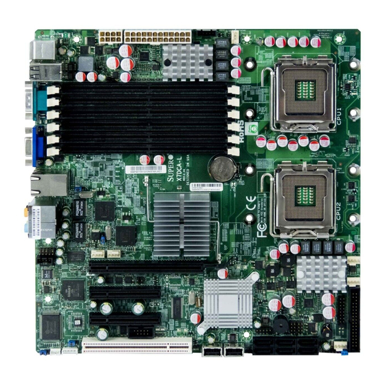
Page 11: X7Dca-L Image
Chapter 1: Introduction X7DCA-L Image Note: The drawings and pictures shown in this manual were based on the latest PCB Revision available at the time of publishing of the manual. The motherboard you’ve received may or may not look exactly the same as the graphics shown in the manual. - Page 12 2. See Chapter 2 for detailed information on jumpers, I/O ports and JF1 front panel connections. 3. " " indicates the location of Pin 1. 4. For RAID configuration and OS installation instructions, please refer to the user guides posted on our web site at www.supermicro.com.
-
Page 13: Quick Reference
Chapter 1: Introduction X7DCA-L Quick Reference Jumper Description Default Setting JBT1 CMOS Clear (See Section 5-10) C1/JI C to PCI/PCI-X/E Slots Open (Disabled) JPG1 VGA Enable Pins 1-2 (Enabled) JPL1/JPL2 LAN1/2 Enable/Disable Pins 1-2 (Enabled) JWD1 Watch Dog Pins 1-2 (Reset) Connector Description Audio/J139/CD1... -
Page 14: Motherboard Features
X7DCA-L User's Manual Motherboard Features • Dual Intel 64-bit Xeon LGA 771 Quad-Core/Dual-Core 5400/5300/5200/5100 ® Series processors at a front side bus speed of 1333 MHz/1066 MHz Memory • Six 240-pin DIMM sockets with support up to 48 GB ECC Buffered (Registered) DDR2 667/533 Memory (*See Section 2-3 in Chapter 2 for DIMM Slot Popula- tion.) Chipset... - Page 15 BIOS flash upgrade utility and device drivers Dimensions • Micro ATX 10.00" (L) x 10.00" (W) (254.00 mm x 254.00 mm) Note: For RAID configuration and Linux OS installation instructions, please refer to the user guides posted on our web site at www.supermicro. com/support/manuals.
- Page 16 X7DCA-L User's Manual Processor #2 Processor #1 ISL6312A ISL6312A 1067/1333 MT/S 1067/1333 MT/S PCI-Ex8 Ports #2,3 Intel 5100 PCI-Ex16 Ports #4,5,6,7 Port #0 PCIEx4 PCI-Ex1 Lane 5 JLAN 82573L Dual RJ45 PCI-Ex1 3.0Gb/S ICH9R Lane 6 82573L Lanes 1/2/3/4 GDDR2 SDRAM 32MB PCI33MMz Volari/Z9S Conn.
-
Page 17: Chipset And Processor Features Overview
Chapter 1: Introduction Chipset and Processor Features Overview Built upon the functionality and the capability of the Intel 5100 chipset, the X7DCA-L motherboard provides the performance and feature set required for dual processor-based high-end computer systems with configuration options optimized for intensive computing, high energy-efficiency and complex business applications. -
Page 18: Special Features
X7DCA-L User's Manual Special Features Recovery from AC Power Loss BIOS provides a setting for you to determine how the system will respond when AC power is lost and then restored to the system. You can choose for the system to remain powered off (in which case you must hit the power switch to turn it back on) or for it to automatically return to a power- on state. -
Page 19: Acpi Features
Chapter 1: Introduction CPU Overheat LED and Control This feature is available when the user enables the CPU overheat warning function in the BIOS. This allows the user to define an overheat temperature. When the CPU temperature reaches the pre-defined overheat threshold, both the overheat fan and the warning LED are triggered. -
Page 20: Power Supply
X7DCA-L User's Manual Main Switch Override Mechanism When an ATX power supply is used, the power button can function as a system suspend button to make the system enter a SoftOff state. The monitor will be suspended and the hard drive will spin down. Pressing the power button again will cause the whole system to wake-up. -
Page 21: Super I/O
Chapter 1: Introduction Super I/O The disk drive adapter functions of the Super I/O chip include a floppy disk drive controller that is compatible with industry standard 82077/765, a data separator, write pre-compensation circuitry, decode logic, data rate selection, a clock generator, drive interface control logic and interrupt and DMA logic. - Page 22 X7DCA-L User's Manual Notes 1-14...
-
Page 23: Chapter 2: Installation
Chapter 2: Installation Chapter 2 Installation Static-Sensitive Devices Electro-Static-Discharge (ESD) can damage electronic com ponents. To prevent damage to your system board, it is important to handle it very carefully. The following measures are generally sufficient to protect your equipment from ESD. Precautions •... -
Page 24: Processor And Heatsink Installation
X7DCA-L User's Manual Processor and Heatsink Installation Warning: When handling the processor package, avoid placing direct pressure on the label area of the fan. Notes: Always connect the power cord last and always remove it before adding, removing or changing any components. Make sure that you install the pro- cessor into the CPU socket before you install the CPU heatsink. -
Page 25: Loading The Processor Into The Socket
Chapter 2: Installation Loading the Processor into the Socket North Align CPU Pin1 (the CPU corner Center marked with a triangle) against the Edge socket corner that is marked with a South triangle cutout. Center Edge Align the CPU key that is the gold dot semi-circle cutout below a gold dot Socket Key... -
Page 26: Installing The Heatsink
X7DCA-L User's Manual Installing the Heatsink CEK Heatsink Installation CEK Passive Heatsink Do not apply any thermal grease to the heatsink or the CPU die; the required amount has already been applied. Place the heatsink on top of the CPU so that the four mounting holes are Screw#1 Screw#2... -
Page 27: Mounting The Motherboard In The Chassis
Chapter 2: Installation Unscrew and remove the heatsink screws from the motherboard in the sequence as shown in the picture on the right. Hold the heatsink as shown in the pic- ture on the right and gently wriggle the heatsink to loosen it from the CPU. (Do not use excessive force when wriggling the heatsink!!) Once the heatsink is loosened, remove... -
Page 28: Installing Dimms
X7DCA-L User's Manual Installing DIMMs Note: Check the Supermicro web site for recommended memory modules. CAUTION Exercise extreme care when installing or removing DIMM modules to prevent any possible damage. Also note that the memory is interleaved to improve performance (see step 1). -
Page 29: Installing And Removing Dimms
Chapter 2: Installation Possible System Memory Allocation & Availability System Device Size Physical Memory Remaining (-Available) (4 GB Total System Memory) Firmware Hub flash memory (System BIOS) 1 MB 3.99 Local APIC 4 KB 3.99 Area Reserved for the chipset 2 MB 3.99 I/O APIC (4 Kbytes) -
Page 30: Back Panel Connectors/Io Ports
X7DCA-L User's Manual Control Panel Connectors/IO Ports The I/O ports are color coded in conformance with the PC 99 specification. See Figure 2-3 below for the colors and locations of the various I/O ports. Back Panel Connectors/IO Ports X7DCA-L Back Panel I/O Port Locations and Definitions Back Panel Connectors Keyboard (Purple) LAN 1... -
Page 31: Front Control Panel
These connectors are designed specifi- cally for use with Supermicro server chassis. See Figure 2-4 for the descriptions of the various control panel buttons and LED indicators. Refer to the following section for descriptions and pin definitions. -
Page 32: Front Control Panel Pin Definitions
X7DCA-L User's Manual Front Control Panel Pin Definitions NMI Button NMI Button Pin Definitions (JF1) The non-maskable interrupt button Pin# Definition header is located on pins 19 and 20 Control of JF1. Refer to the table on the right for pin definitions. Ground Power LED Power LED Pin Definitions (JF1) The Power LED connection is located Pin#... -
Page 33: Hdd Led
Chapter 2: Installation HDD LED The HDD LED connection is located HDD/UID LED on pins 13 and 14 of JF1. Attach a Pin Definitions (JF1) hard drive LED cable here to display Pin# Definition disk activity (for any hard drives on the Vccl system, including SAS, Serial ATA and HD Active... -
Page 34: Overheat/Fan Fail Led
X7DCA-L User's Manual Overheat/Fan Fail LED (OH) OH/Fan Fail LED Pin Definitions (JF1) Connect an LED to the OH/Fan Fail Pin# Definition connection on pins 7 and 8 of JF1 to provide advanced warnings of chassis Ground overheating or fan failure. Refer to the table on the right for pin definitions. -
Page 35: Reset Button
Chapter 2: Installation Reset Button Reset Button The Reset Button connection is located Pin Definitions (JF1) on pins 3 and 4 of JF1. Attach it to the Pin# Definition hardware reset switch on the computer Reset case. Refer to the table on the right for Ground pin definitions. -
Page 36: Connecting Cables
X7DCA-L User's Manual Connecting Cables ATX Power 24-pin Connector Pin Definitions ATX Power Connector Pin# Definition Pin # Definition +3.3V +3.3V A 24-pin main power supply con- -12V +3.3V nector is located at JPW2 on the motherboard. This power connector PS_ON meets the SSI EPS 12V specifica- tion. -
Page 37: Universal Serial Bus (Usb)
Chapter 2: Installation Universal Serial Bus (USB) Back Panel USB (USB 0~3) There are eight USB 2.0 (Universal Pin# Definitions Serial Bus) ports/headers on the motherboard. Four of them are Back Panel USB ports: USB 0~3 (JPUSB1). The other four are Front Panel USB Ground connectors: USB 4~5 (JUSB3), USB 6 (JUSB4), and USB 7 (JUSB5). -
Page 38: Fan Headers
X7DCA-L User's Manual Fan Headers The X7DCA-L has six CPU/system fan Fan Header Pin Definitions headers (Fans 1~Fan 6). All these fans are Pin# Definition 4-pin fans. See the table on the right for pin definitions. Ground +12V Note: The onboard fan speeds are Tachometer controlled by Thermal Management via BIOS Hardware Monitoring in the... -
Page 39: Atx Ps/2 Keyboard And Mouse Ports
Chapter 2: Installation ATX PS/2 Keyboard and PS/2 PS/2 Keyboard and Mouse Ports Mouse Port Pin Definitions The ATX PS/2 keyboard and the Pin# Definition PS/2 mouse are located on the IO Data Backpanel. See the table on the right for pin definitions. -
Page 40: Wake-On-Ring
X7DCA-L User's Manual Wake-On-Ring The Wake-On-Ring header is located at JWOR1. This feature allows your Wake-On-Ring Pin Definitions computer to be "awakened" by an Pin# Definition incoming call to the modem when the Ground system is in the suspend state. See Wake-up the table on the right for pin defini- tions. -
Page 41: Power Led/Speaker Header
Chapter 2: Installation GLAN 1/2 (Giga-bit Ethernet Ports) Two G-bit Ethernet ports are located at JLAN3 on the I/O backplane. These ports accept RJ45 type cables. GLAN1/2 Power LED/Speaker On the JD1 header, pins 1-3 are for a Speaker Connector power LED, and pins 4-7 are for the Pin Definitions speaker. -
Page 42: Power Smb Connector
X7DCA-L User's Manual T-GPIO Headers Two GPIO (Serial-Link General Pur- T-GPIO1/2 Pin Definitions pose Input/Output) headers are located Pin# Definition Definition at J7 and J8 on the motherboard. These headers are used to communicate with Ground DATA Out the Serial-Link System Monitoring chip Load Ground on the backplane. -
Page 43: High Definition Audio
Chapter 2: Installation High Definition Audio (HDA) This motherboard features a 7.1+2 Channel Orange: Blue: Line-In CEN/LFE High Definition Audio (HDA) codec that provides 10 DAC channels, simultaneously Black: Back Green:Front Surround supporting 7.1 sound playback, and two Grey: Side channels of independent stereo sound output Pink: Mic-In Surround (multiple streaming) through the front panel... -
Page 44: Smb
X7DCA-L User's Manual Auxiliary Front Panel Audio Control When the front panel headphones are HD Front Panel Audio plugged in, the back panel audio output Pin Definitions is disabled. This is done through the Pin# Signal FP Audio header (J139). If the front MIC_L panel interface card is not connected to AUD_GND... -
Page 45: Jumper Settings
Chapter 2: Installation Jumper Settings Explanation of Connector Jumpers Pins To m o d i f y t h e o p e r a t i o n o f t h e motherboard, jumpers can be used Jumper to choose between optional settings. -
Page 46: Cmos Clear
X7DCA-L User's Manual CMOS Clear JBT1 is used to clear CMOS. Instead of pins, this "jumper" consists of contact pads to prevent the accidental clearing of CMOS. To clear CMOS, use a metal object such as a small screwdriver to touch both pads at the same time to short the connection. -
Page 47: I 2 C Bus To Pci Slots
Chapter 2: Installation C Bus to PCI Slots C to PCI-Slots Jumpers JI C1 and JI C2 allow you to con- Jumper Settings nect the System Management Bus (I C) to Jumper Definition PCI-E and PCI slots. The default setting is Enabled set to Disabled. -
Page 48: Onboard Indicators
X7DCA-L User's Manual Onboard Indicators Activity L i n k GLAN LEDs Rear View There are two GLAN ports on the moth- (when viewing from the back of the chassis.) erboard. Each Gigabit Ethernet LAN port GLAN Activity Indicator has two LEDs. The green LED indicates LED Setting activity, while the Link LED may be Color... -
Page 49: Cpu_Vrm Overheat Leds
Chapter 2: Installation CPU_VRM Overheating LED Indicators (LED5/LED6) CPU_VRM Overheat LED Indicators Two CPU VRM Overheat LED In- d i c a t o r s a r e l o c a t e d a t L E D 5 LED# Description and LED6 on the motherboard. -
Page 50: Floppy Connector
X7DCA-L User's Manual Floppy Drive Connection Note the following when connecting the floppy and hard disk drive cables: • The floppy disk drive cable has seven twisted wires. • A red mark on a wire typically designates the location of pin 1. Floppy Drive Connector Floppy Connector Pin Definitions (Floppy) -
Page 51: Chapter 3: Troubleshooting
Chapter 3: Troubleshooting Chapter 3 Troubleshooting Troubleshooting Procedures Use the following procedures to troubleshoot your system. If you have followed all of the procedures below and still need assistance, refer to the ‘Technical Support Procedures’ and/or ‘Returning Merchandise for Service’ section(s) in this chapter. Note: Always disconnect the power cord before adding, changing or installing any hardware components. -
Page 52: No Video
X7DCA-L User's Manual No Video If the power is on but you have no video, remove all the add-on cards and cables. Use the speaker to determine if any beep codes exist. Refer to the Appendix for details on beep codes. Losing the System’s Setup Configuration Make sure that you are using a high quality power supply. -
Page 53: Technical Support Procedures
Technical Support Procedures Before contacting Technical Support, please take the following steps. Also, note that as a motherboard manufacturer, Supermicro does not sell directly to end-users, so it is best to first check with your distributor or reseller for troubleshooting services. -
Page 54: Returning Merchandise For Service
Answer: It is recommended that you do not upgrade your BIOS if you are experi- encing no problems with your system. Updated BIOS files are located on our web site at http://www.supermicro.com/support/bios/. Please check our BIOS warning message and the information on how to update your BIOS on our web site. Also, check the current BIOS revision, and make sure that it is newer than your BIOS before downloading. -
Page 55: Chapter 4: Bios
Note: Due to periodic changes to the BIOS, some settings may have been added or deleted and might not yet be recorded in this manual. Please refer to the Manual Download area of the Supermicro web site <http://www. supermicro.com> for any changes to the BIOS that may not be reflected in this manual. -
Page 56: Running Setup
X7DCA-L User's Manual Running Setup Default settings are in bold text unless otherwise noted. The BIOS setup options described in this section are selected by choosing the ap- propriate text from the main BIOS Setup screen. All displayed text is described in this section, although the screen display is often all you need to understand how to set the options as shown on the following page. -
Page 57: Main Bios Setup Menu
Chapter 4: BIOS Main BIOS Setup Menu Main Setup Features System Time To set the system date and time, key in the correct information in the appropriate fields. Then press the <Enter> key to save the data. System Date Using the arrow keys, highlight the month, day and year fields, and enter the correct data. - Page 58 X7DCA-L User's Manual Type This option allows the user to select the type of IDE hard drive. Select Auto to allow the BIOS to automatically configure the parameters of the HDD installed at the connection. Select User to allow the user to enter the parameters of the HDD installed.
- Page 59 Chapter 4: BIOS Ultra DMA Mode This option allows the user to select Ultra DMA Mode for the slot specified. The options are Disabled, Mode 0, Mode 1, Mode 2, Mode 3, Mode 4, and Mode 5. Serial ATA This setting allows the user to enable or disable the function of Serial ATA. The options are Disabled and Enabled.
- Page 60 X7DCA-L User's Manual System Memory This display informs you how much system memory is detected by the BIOS. Extended Memory This display informs you how much extended memory in the system is detected by the BIOS.
-
Page 61: Advanced Setup
Chapter 4: BIOS Advanced Setup Choose Advanced from the Phoenix BIOS Setup Utility main menu with the ar- row keys. You should see the following display. The items with a triangle beside them have sub menus that can be accessed by highlighting the item and pressing <Enter>. - Page 62 X7DCA-L User's Manual Power Button Behavior If set to Instant-Off, the system will power off immediately as soon as the user hits the power button. If set to 4-Sec Override, the system will power off when the user presses the power button for 4 seconds or longer. The options are Instant-off and 4-sec override.
-
Page 63: Memory Cache
Chapter 4: BIOS Memory Cache Cache System BIOS Area This setting allows you to designate a reserve area in the system memory to be used as a System BIOS buffer to allow the BIOS to write (cache) its data into this reserved memory area. - Page 64 X7DCA-L User's Manual Cache Extended Memory Area If enabled, this feature allows the data stored in the extended memory area to be cached (written) into a buffer, a storage area in the Static DROM (SDROM) or written into L1, L2, L3 cache inside the CPU to speed up CPU operations. Select Uncached to disable this function.
-
Page 65: Advanced Chipset Control
Chapter 4: BIOS Enable Master This setting allows you to enable the selected device as the PCI bus master. The options are Enabled and Disabled. Latency Timer This setting allows you to set the clock rate for the Bus Master. A high-priority, high-throughout device may benefit from a greater clock rate. - Page 66 X7DCA-L User's Manual SERR Signal Condition This setting specifies the ECC Error conditions that an SERR# is to be asserted. The options are None, Single Bit, Multiple Bit, and Both. 4GB PCI Hole Granularity This feature allows you to select the granularity of PCI hole for PCI slots. If MTRRs are not enough, this option may be used to reduce MTRR occupation.
-
Page 67: Advanced Processor Options
Chapter 4: BIOS USB Host Controller Select Enabled to activate the USB Host Controller. The settings are Enabled and Disabled. Legacy USB Support This setting allows you to enable support for Legacy USB devices. The settings are Enabled and Disabled. Azalia Audio When set to Auto, Azalia Audio will be automatically turned on when detected by the BIOS. - Page 68 X7DCA-L User's Manual Execute Disable Bit (Available when supported by the CPU and the OS.) Set to Enabled to enable Execute Disable Bit and allow the processor to classify areas in memory where an application code can execute and where it cannot, and thus preventing a worm or a virus from inserting and creating a flood of codes to overwhelm the processor or damage the system during an attack.
- Page 69 Chapter 4: BIOS CPU Cache Control DCU Prefetcher (Available when supported by the CPU.) The CPU fetches the cache line for 64 bytes if this option is set to Disabled. The CPU fetches both cache lines for 128 bytes as comprised if Enabled. The options are Disabled and Enabled.
-
Page 70: Dmi Event Logging
X7DCA-L User's Manual Serial Port B This setting allows you to assign control of serial port B. The options are Enabled (user defined), Disabled and Auto (BIOS controlled). Mode This setting allows you to set the type of device that will be connected to serial port B. -
Page 71: Console Redirection
Chapter 4: BIOS Mark DMI Events as Read Highlight this item and press <Enter> to mark the DMI events as read. Clear All DMI Event Logs Select Yes and press <Enter> to clear all DMI event logs. The options are Yes and No. -
Page 72: Hardware Monitor
X7DCA-L User's Manual Hardware Monitor Highlight an item and hit <Enter> to see the status of each of the following items: CPU Overheat Alarm This option allows the user to select the CPU Overheat Alarm setting which de- termines when the CPU OH alarm will be activated to provide warning of possible CPU overheat. - Page 73 ‘Temperature Tolerance’ is, and not the other way around. This results in better CPU thermal management. Supermicro has leveraged this feature by assigning a temperature status to certain thermal conditions in the processor (Low, Medium and High). This makes it easier for the user to understand the CPU’s temperature status,...
- Page 74 X7DCA-L User's Manual Fan Speed Control Modes This feature allows the user to decide how the system controls the speeds of the onboard fans. The CPU temperature and the fan speed are correlative. When the CPU on-die temperature increases, the fan speed will also increase, and vice versa. Select Workstation if your system is used as a Workstation.
- Page 75 Chapter 4: BIOS Security Choose Security from the Phoenix BIOS Setup Utility main menu with the arrow keys. You should see the following display. Security setting options are displayed by highlighting the setting using the arrow keys and pressing <Enter>. All Security BIOS settings are described in this section.
- Page 76 X7DCA-L User's Manual Password on Boot This setting allows you to determine if a password is required for a user to enter the system at system boot. The options are Enabled (password required) and Disabled (password not required). 4-22...
- Page 77 Chapter 4: BIOS Boot Choose Boot from the Phoenix BIOS Setup Utility main menu with the arrow keys. You should see the following display. See details on how to change the order and specs of boot devices in the Item Specific Help window. All Boot BIOS settings are described in this section.
-
Page 78: Exit
X7DCA-L User's Manual Exit Choose Exit from the Phoenix BIOS Setup Utility main menu with the arrow keys. You should see the following display. All Exit BIOS settings are described in this section. Exit Saving Changes Highlight this item and hit <Enter> to save any changes you made and to exit the BIOS Setup utility. - Page 79 Appendix A: BIOS POST Messages Appendix BIOS POST Messages During the Power-On Self-Test (POST), the BIOS will check for problems. If a problem is found, the BIOS will activate an alarm or display a message. The fol- lowing is a list of such BIOS messages. Failure Fixed Disk Fixed disk is not working or not configured properly.
- Page 80 X7DCA-L User's Manual Extended RAM Failed at offset: nnnn Extended memory not working or not configured properly at offset nnnn. System battery is dead - Replace and run SETUP The CMOS clock battery indicator shows the battery is dead. Replace the battery and run Setup to reconfigure the system.
- Page 81 Appendix A: BIOS POST Messages Diskette drive A error Drive A: is present but fails the BIOS POST diskette tests. Check to see that the drive is defined with the proper diskette type in Setup and that the diskette drive is attached correctly.
- Page 82 X7DCA-L User's Manual CD ROM Drive CD ROM Drive identified. Entering SETUP ... Starting Setup program Failing Bits: nnnn The hex number nnnn is a map of the bits at the RAM address which failed the memory test. Each 1 (one) in the map indicates a failed bit. See errors 230, 231, or 232 above for offset address of the failure in System, Extended, or Shadow memory.
-
Page 83: Appendix A: Bios Post Messages
Appendix A: BIOS POST Messages nnnn kB System RAM Passed Where nnnn is the amount of system RAM in kilobytes successfully tested. One or more I2O Block Storage Devices were excluded from the Setup Boot Menu There was not enough room in the IPL table to display all installed I2O block- storage devices. - Page 84 X7DCA-L User's Manual Run the I2O Configuration Utility One or more unclaimed block storage devices have the Configuration Request bit set in the LCT. Run an I2O Configuration Utility (e.g. the SAC utility). System BIOS shadowed System BIOS copied to shadow RAM. UMB upper limit segment address: nnnn Displays the address nnnn of the upper limit of Upper Memory Blocks, indicat- ing released segments of the BIOS which can be reclaimed by a virtual memory manager.
-
Page 85: Appendix B: Bios Post Codes
Appendix B: BIOS POST Codes Appendix B BIOS POST Codes This section lists the POST (Power On Self Test) codes for the Phoenix BIOS. POST codes are divided into two categories: recoverable and terminal. Recoverable POST Errors When a recoverable type of error occurs during POST, the BIOS will display an POST code that describes the problem. - Page 86 X7DCA-L User's Manual POST Code Description Initialize Power Management Load alternate registers with initial POST values Restore CPU control word during warm boot Reset PCI Bus Mastering devices Initialize keyboard controller 1-2-2-3 BIOS ROM checksum Initialize cache before memory Auto size 8254 timer initialization 8237 DMA controller initialization Reset Programmable Interrupt Controller...
- Page 87 Appendix B: BIOS POST Codes POST Code Description Initialize PCI bus and devices Initialize all video adapters in system QuietBoot start (optional) Shadow video BIOS ROM Display BIOS copyright notice Initialize MultiBoot Display CPU type and speed Initialize EISA board (optional) Test keyboard Set key click if enabled Enable USB devices...
- Page 88 X7DCA-L User's Manual POST Code Description Disable onboard Super I/O ports and IRQs (optional) Late POST device initialization Detect and install external RS232 ports Configure non-MCD IDE controllers Detect and install external parallel ports Initialize PC-compatible PnP ISA devices Re-initialize onboard I/O ports. Configure Motherboard Configurable Devices (optional) Initialize BIOS Data Area...
- Page 89 Appendix B: BIOS POST Codes POST Code Description Erase <ESC> prompt Scan for <ESC> key stroke Enter SETUP Clear Boot flag Check for errors Inform RomPilot about the end of POST (optional) POST done - prepare to boot operating system 1 One short beep before boot Terminate QuietBoot (optional) Check password (optional)
- Page 90 X7DCA-L User's Manual The following are for boot block in Flash ROM POST Code Description Initialize the chipset Initialize the bridge Initialize the CPU Initialize system timer Initialize system I/O Check force recovery boot Checksum BIOS ROM Go to BIOS Set Huge Segment Initialize Multi Processor Initialize OEM special code...
-
Page 91: Installing The Windows Os
RAID settings before you install the OS and other software drivers. To install the Linux OS or to configure RAID settings, please refer to the OS Installation or RAID Configuration User Guides posted on our web site at www.supermicro.com/support/ manuals. - Page 92 After the Windows XP/2000/2003 Installation is completed, the system will automatically reboot. Insert the Supermicro Setup CD that came with the package into the CD Drive during system reboot, and the main screen will appear. C-2 Installing the Windows XP/2000/2003 OS to...
-
Page 93: Appendix D: Installing Other Software And Drivers
2. To install the Linux OS or to configure RAID settings, please refer to the OS Installation or RAID Configuration User Guides posted on our web site at www.supermicro.com/support/manuals. - Page 94 X7DCA-L User's Manual D-2 Configuring Supero Doctor III The Supero Doctor III program is a Web-based management tool that supports remote management capability. It includes Remote and Local Management tools. The local management is called the SD III Client. The Supero Doctor III program included on the CDROM that came with your motherboard allows you to monitor the environment and operations of your system.
- Page 95 Supero Doctor III Interface Display Screen-II (Remote Control) Note: SD III Software can be downloaded from our Web site at: ftp://ftp. supermicro.com/utility/Supero_Doctor_III/. You can also download SDIII User's Guide at: http://www.supermicro.com/PRODUCT/Manuals/SDIII/ UserGuide.pdf. For the Linux OS, we will still recommend that you use...
- Page 96 X7DCA-L User's Manual Notes...
- Page 97 (Disclaimer) The products sold by Supermicro are not intended for and will not be used in life support systems, medical equipment, nuclear facilities or systems, aircraft, aircraft devices, aircraft/emergency communication devices or other critical systems whose failure to perform be reasonably expected to result in significant injury or loss of life or catastrophic property damage.