Table of Contents
Advertisement
Waterproof construction
Commercial grade ITU Class D DSC VHF
Independent Channel 70 receiver built-in for continuous DSC watching
Capable of connecting up to one second station microphone
Intercom between radio and second station microphone
DSC position request and send functions with compatible STANDARD
HORIZON GPS Chart plotters
Versatile user-programmable scanning, priority scan and Dual Watch
One-button access to Channel 16 and 9
Oversized rotary channel knob, backlit display and keys.
Navigation information shown on display when optional GPS connected
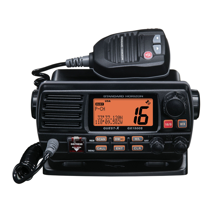
GX1500S
QUEST-X GX1500S
ITU Class D DSC Marine Transceiver
Owner's Manual
25 Watt VHF/FM
Page 1
Advertisement
Table of Contents

Related Manuals for Standard Horizon Quest-X GX1500S


Summary of Contents for Standard Horizon Quest-X GX1500S
- Page 1 One-button access to Channel 16 and 9 Oversized rotary channel knob, backlit display and keys. Navigation information shown on display when optional GPS connected GX1500S QUEST-X GX1500S ITU Class D DSC Marine Transceiver Owner's Manual 25 Watt VHF/FM Page 1...
-
Page 2: Table Of Contents
11.3.1 Tansmitting a DSC Distress Call ... 34 11.3.2 Receiving a DSC Distress Call ... 36 11.4 ALL SHIPS CALL ... 36 11.4.1 Transmitting an All Ships Call ... 37 11.4.2 Receiving an All Ships Call ... 37 Page 2 GX1500S... - Page 3 14.4.2 External Speaker AF Selection ... 77 15 MAINTENANCE ... 78 15.1 REPLACEMENT PARTS ... 78 15.2 FACTORY SERVICE ... 79 15.3 TROUBLESHOOTING CHART ... 80 16 CHANNEL ASSIGNMENTS ... 82 17 WARRANTY ... 88 18 SPECIFICATIONS ... 91 GX1500S Page 3...
-
Page 4: General Information
The Vertex Standard GX1500S is a VHF/FM transceiver designed for use in the frequency range of 156.025 to 163.275 MHz. The GX1500S can be oper- ated from 11 to 16 VDC and has a switchable RF output power of 1 watt or 25 watts. -
Page 5: Safety / Warning Information
Marine Division of Vertex Standard Web site. PRODUCT SUPPORT INQUIRIES If you have any questions or comments regarding the use of the GX1500S, you can visit the Marine Division of Vertex Standard Web site to send an E-Mail or contact the Product Support team at 800-767-2450 M-F 7:00- 5:00PST. -
Page 6: Fcc Radio License Information
Type Acceptance ... FCC Part 80 Output Power ... 1 Watt (low) and 25 Watts (high) Emission ... 16K0G3E, 16K0G2B Frequency Range ... 156.025 to 163.275 MHz FCC Type Number ... K6630173X3D Industry Canada Type Approval ... 511B-30173X3D Page 6 GX1500S... -
Page 7: Fcc Notice
- Increase the separation between the equipment and receiver. - Connect the equipment into an outlet on a circuit different from that to which the receiver is connected. - Consult the dealer or an experienced radio/TV technician for help. GX1500S NOTICE NOTICE Page 7... -
Page 8: Getting Started
A 3 foot, 3dB gain antenna represents twice as much gain over the imaginary antenna. Typically a 3 foot 3dB gain stainless steel whip is used on a sailboat mast. The longer 8 foot 6dB fiberglass whip is primarily used on power boats that require the additional gain. Page 8 GX1500S... -
Page 9: Coaxial Cable
To get your coax cable through a fitting and into your boat’s interior, you may have to cut off the end plug and reattach it later. You can do this if you follow the directions that come with the connector. Be sure to make good soldered connections. GX1500S 1/16'' 3/4'' 1 1/8''... -
Page 10: Installation
8 INSTALLATION 8.1 LOCATION The radio can be mounted at any angle. Choose a mounting location that: • is far enough from any compass to avoid any deviation in compass read- ing due to the speaker magnet • provides accessibility to the front panel controls •... -
Page 11: Accessory Cable
2. Connect the red power wire to a 13.8 VDC ±20% power source. Connect the black power wire to a negative ground. 3. If an optional remote extension speaker is to be used, refer to next section for connections. 4. It is advisable to have a Certified Marine Technician check the power output and the standing wave ratio of the antenna after installation. -
Page 12: Connection Of Gps With Nmea Output
LCD display. To see the additional GPS information, press and hold the [ H/L ( NAV )] key. The GX1500S shows the Date, Time, SOG and COG. Page 12... -
Page 13: Changing The Gps Time
8.6 CHANGING THE GPS TIME From the Factory the GX1500S shows GPS satellite time or UTC time. A time offset is needed to show the local time in your area. 1. Press and hold down the [ CALL ( MENU )] key until “... -
Page 14: Changing The Time Location
Page 14 Time Disp ” in the ( “LOCAL” mode ) Magnetic ” with the ” (representing “True”). ” and press the [ ENT ] key Exit ” or ” (rep- Exit ,” Radio GX1500S... -
Page 15: Optional Mmb-84 Flush Mount Installation
(see Figure 2). 5. Turn the adjusting screw to adjust the tension so that the transceiver is tight against the mounting surface. Bracket Lock-washer nut combination Figure 2. MMB-84 Flush Mount Installation GX1500S Adjusting Screw Page 15... -
Page 16: Optional Enhanced Ram+ Second Station Mic And/Or Vh-310 Handset Installation
8.10 OPTIONAL ENHANCED RAM+ SECOND STATION MIC AND/OR VH-310 HANDSET INSTALLATION The GX1500S is capable of using a Enhanced RAM+ mic or VH-310 Handset to remotely control the Radio, DSC, and Distress functions. In addition the GX1500S can operate as a full function intercom system. - Page 17 “ ” (External speaker on). 6. Press the [ ENT ] key to save the selection. 7. Press the [ 16/9 ] key to exit this mode. GX1500S RADIO SETUP EXT SPK ” is shown and press the ”...
-
Page 18: Controls And Indicators
Adjusting this control clockwise, sets the point at which random noise on the channel does not activate the audio circuits but a received signal does. This point is called the squelch threshold. Further adjustment of the squelch control will degrade reception of wanted transmissions. Page 18 NOTE GX1500S... - Page 19 Figure 4. Controls and Connectors GX1500S Page 19...
- Page 20 Press and hold this key, the LCD displays NAV GPS Data, Time, SOG (Speed Over Ground), and COG (Course Over Ground) when a GPS is connected to the accessory cable of the GX1500S. See section “8.4 CONNECTION OF GPS WITH NMEA OUTPUT” for details.
- Page 21 Keys the transmitter when the transceiver is in radio mode. If the transceiver is in the intercom mode (between the RAM+ or VH-310 Headset and the GX1500S), or PA mode, it activates the GX1500S microphone for voice com- munications. GX1500S GROUP CALL ,”...
- Page 22 The [ 16/9 ] key on the microphone function the same as the [ 16/9 ] key on the front panel of the transceiver. Immediately recalls channel 16 from any channel location. Holding down this key recalls channel 9. Pressing the [ 16/9 ] key again reverts to the pre- vious selected working channel. Page 22 GX1500S...
- Page 23 MEMO GX1500S Page 23...
-
Page 24: Basic Operation
The transceiver will automatically go to receive mode, even if the PTT switch is continually held down. Before transmitting again, the PTT switch must first be released and then pressed again. Page 24 ” indicator in the LCD is NOTE GX1500S... -
Page 25: Simplex/Duplex Channel Use
Follow the same procedure as for regular channels under section “10.12 SCANNING.” 2. Press the [ SCAN ] key once to start memory scanning or priority scanning (determined from the “ GX1500S NOTE NOTE Radio Setup ” selection, see page 56 for details). -
Page 26: Noaa Weather Alert Testing
10.6.2 NOAA Weather Alert Testing NOAA tests the alert system every Wednesday between 11AM and 1PM. To test the GX1500S’s NOAA Weather alert feature, on Wednesday between 11AM and 1PM, setup as in previous section and confirm the alert is heard. -
Page 27: Calling Another Vessel (Channel 16 Or 9)
Channels available for such traffic are designated Public Correspondence channels on the channel charts in this manual. Some ex- amples for USA use are Channels 24, 25, 26, 27, 28, 84, 85, 86, and 87. Call GX1500S Page 27... -
Page 28: Operating On Channels 13 And 67
2. If a transmission is received on the channel selected in step 2, the GX1500S will dual watch between the working channel and the Priority channel. 4. To stop Dual Watch, press the [ DW ( IC )] key again. -
Page 29: Scanning
6. The channel number will blink during reception. 7. To stop scanning, press the [ 16/9 ] or [ WX ] key. GX1500S SCAN Type ” in the ” appears on the LCD. Scan-... -
Page 30: Priority Scanning P-Scan
NOTE: When Ch16 is selected only lat/lon will shown. 2. To hide the position information, press and hold the [ H/L ( NAV )] key again. Page 30 P-SCAN ” appears GX1500S... -
Page 31: Intercom Operation
[ 16/9 ] or [ CLR ] key. 10.14.2 Calling While in INTERCOM mode, pressing and holding the [ DW ( IC )] key on the GX1500S, CMP25 or VH-310 will produce a calling beep at the other station. GX1500S Intercom Talk ”... -
Page 32: Digital Selective Calling
20 nautical miles. A DSC Warning sticker is included with the GX1500S. To comply with FCC regulations this sticker must be mounted in a location that can be eas- ily viewed from the location of the GX1500S. -
Page 33: Maritime Mobile Service Identity (Mmsi)
Digital Selective Calling (DSC). This number is used like a telephone number to selectively call other vessels. THIS NUMBER MUST BE PROGRAMMED INTO THE RADIO TO OPERATE THE GX1500S DSC FUCTIONS. How can I obtain an MMSI assignment? Boat US offers online registration of a MMSI. Visit www.boatus.com/mmsi 11.2.2 Programming the MMSI... -
Page 34: Dsc Distress Call
11.3 DSC DISTRESS CALL The GX1500S is capable of transmitting and receiving DSC Distress messages to all DSC radios. The GX1500S may be connected to a GPS to also transmit the Latitude, Longitude of the vessel. 11.3.1 Transmitting a DSC Distress Call To be able to transmit a DSC distress call an MMSI number must be programmed, refer to section “11.2.2 Programming the MMSI.”... - Page 35 Transmitting a DSC Distress Call with Nature of Distress The GX1500S is capable of transmitting a DSC Distress Call with the following “Nature of Distress” categories: Undesignated, Fire, Flooding, Collision, Grounding, Capsizing, Sinking, Adrift, Abandoning, Piracy, Mob 1. Lift the red spring loaded DISTRESS cover and press the [DISTRESS] key.
-
Page 36: Receiving A Dsc Distress Call
Used to transmit boating safety information to other vessels. This message usually contains information about an overdue boat, debris in the water, loss of a navigation aid or an impor- tant meteorological message. This call is the same as saying Securite, Securite, Securite.” Page 36 NOTE GX1500S... -
Page 37: Transmitting An All Ships Call
2. Press any key to stop the alarm. 3. Turn the CHANNEL selector knob to see the MMSI of the vessel transmitting the All Ships Call. 4. Monitor channel 16 or traffic channel until the UR- GENCY voice communication is completed. GX1500S Page 37... -
Page 38: Individual Call
11.5.1 Setting up the Individual / Position Call Directory The GX1500S has a DSC directory that allows you to store a vessel or person’s name and the MMSI number associated with vessels you wish to transmit Indi- vidual calls, Position Requests and Position Send transmissions. -
Page 39: Setting Up Individual Ringer
“ Manual .” 6. Press the [ ENT ] key to store the selected setting. 7. To exit this menu and return to radio operation mode press the [ 16/9 ] key. GX1500S NOTE INDIV Reply ” with Auto ”... -
Page 40: Setting Up Individual / Group Call Ringer
7. To exit this menu and return to radio operation mode press the [ 16/9 ] key. The GX1500S has the capability to turn off the Individual call ringer. 1. Press and hold down the [ CALL ( MENU )] key until “Radio Setup”... -
Page 41: Transmitting An Individual Call
5 above and a ringing tone sounds. 10. Press any key to listen to the channel to make sure it is not busy, then key the microphone and call the other vessel you desire to communicate with. GX1500S Page 41... - Page 42 [ CLR ] key. 12. When an individual call acknowledgment is received, the established chan- nel is automatically changed to the channel which is selected on step 5 above and a ringing tone sounds. Page 42 Manual ,” GX1500S...
-
Page 43: Receiving An Individual Call
11.5.6 Setting Up the Call Waiting Function Allows the GX1500S to be setup to reply (ABLE) or set the radio so it transmits a call that advises the calling vessel the person is UNABLE to reply to the call at this time. -
Page 44: Group Call
10. Turn the CHANNEL selector knob to scroll through numbers, 0-9. To enter the desired number and move one space to the right press the [ ENT ] key. Repeat this procedure until all nine space of the MMSI number are entered. Page 44 Group DIR ” with ” with the GX1500S... -
Page 45: Transmitting A Group Call
8. Listen to the channel to make sure it is not busy, then key the microphone and call the other vessels you desire to communicate with. GX1500S DSC Operation Exit ” with the CHANNEL selector ”... - Page 46 10. Listen to the channel to make sure it is not busy, then key the microphone and call the other vessels you desire to communicate with. Page 46 DSC Operation Exit ” with the CHANNEL selector ” will appear. ” Group .” Manual ,” GX1500S...
-
Page 47: Receiving A Group Call
11.6.3 Receiving a Group Call 1. When a group call is received, the GX1500S will pro- duce a ringing alarm sound. 2. The radio automatically switches to the requested channel. 3. Press any key to stop the alarm. 4. Monitor the channel for the person calling the Group for a message. -
Page 48: Position Request
Advancements in DSC have made it possible to poll the location of another vessel and show the position of that vessel on the display of the GX1500S. Standard Horizon has taken this feature one step further, if any Standard Hori-... -
Page 49: Transmitting A Position Request To Another Vessel
The GX1500S has the capability to turn off the Position Request ringer. 1. Press and hold down the [ CALL ( MENU )] key until “Radio Setup” menu appears. 2. Turn the CHANNEL selector knob to select “DSC Setup” menu. - Page 50 GPS Chart plotter. 10. If the GX1500S does not receive a reply, the display will be as shown in the illustration on the right. To send again, press the [ ENT ] key.
-
Page 51: Receiving A Position Request
“ Send CHANNEL selector knob. 3. The GX1500S display will show “ ” allowing you to send your vessels location by using the CHANNEL selector knob. ” is selected, press the [ ENT ] key. And your position will be Send 4. -
Page 52: Position Send
GX1500S to send the position. 11.8.1 Setting up a Position Send Ringer The GX1500S has the capability to turn off the Position Send ringer. 1. Press and hold down the [ CALL ( MENU )] key until “Radio Setup” menu appears. -
Page 53: Transmitting A Dsc Position Send Call
5. Enter the MMSI number (nine digits) which you want to contact, then press the [ ENT ] key. 6. Press the [ ENT ] key to send your position to the se- lected vessel. GX1500S DSC Operation ” DSC Operation ”... -
Page 54: Receiving A Dsc Position Send Call
11.8.3 Receiving a DSC Position Send Call When another vessel transmits their location to the GX1500S the following will happen: 1. A ringing sound will be produced when the call is received. 2. Press the [ 16/9 ] key to stop ringing 3. -
Page 55: Manual Inputting Of The Gps Location (Lat/Lon)
11.9 MANUAL INPUTTING OF THE GPS LOCATION ( LAT/LON ) You may send the Latitude/Longitude of your vessel manually even if the GX1500S is not connected the GPS receiver unit. After the position is entered, transmitting a DSC Distress, Position Request, or Position Send will contain the manually entered position. -
Page 56: Radio Setup Mode
5. Press the [ ENT ] key to store the selected level. 6. To exit this menu and return to radio operation mode press the [ 16/9 ] key. Page 56 NOTE Dimmer ” is selected, the lamp is ex- Contrast ” in the ” in the ” GX1500S... -
Page 57: Time Offset
GMT Greenwich Mean Time). 5. Press the [ ENT ] key to store the time offset. 6. To exit this menu and return to radio operation mode press the [ 16/9 ] key. GX1500S Time Set ” in the 0:00 ”... -
Page 58: Time Location
6. To exit this menu and return to radio operation mode press the [ 16/9 ] key. Page 58 Time Disp. ” in the ( “LOCAL” mode ) Magnetic ” in the ” (rep- ” (representing “True”). ” or GX1500S... -
Page 59: Priority Channel Set
.” 5. Press the [ ENT ] key to store the selected setting. 6. To exit this menu and return to radio operation mode press the [ 16/9 ] key. GX1500S Priority CH ” in the SCAN Type ” in the... -
Page 60: Scan Resume Time
12.8 SCAN RESUME TIME This selection is used to select the time the GX1500S waits after a transmis- sion ends before starting scanning. 1. Press and hold down the [ CALL ( MENU )] key until “ Radio Setup ” menu appears. -
Page 61: Wx Alert
On SCAN 5. Press the [ ENT ] key to store the selected setting. 6. To exit this menu and return to radio operation mode press the [ 16/9 ] key. GX1500S WX Alert ” in the ,” “ On SCAN WX ,”... -
Page 62: Channel Name Change
10. To exit this menu and return to radio operation mode press the [ 16/9 ] key. Page 62 CH Name ” in the ” menu. The LCD will return to the “ ” then press the [ ENT ] key. Exit Radio Setup ” Next ” then press GX1500S... -
Page 63: Naming The Radio Or Ram+ Stations
9. If you want to enter the name of another unit, repeat steps 4 through 8. 10. To exit this menu and return to radio operation mode press the [ 16/9 ] key. GX1500S Unit Name ”) to be named, then press the ”... -
Page 64: Enhanced Ram+ Mic Opertion
13 ENHANCED RAM+ MIC OPERATION When the RAM+ microphone is connected to the GX1500S, most VHF, DSC, and setup menus can be remotely operated. The RAM+ Mic is supplied with 23 feet (7 m) of routing cable and can be extended up to 70 feet (21 m) using three 23 feet extension cables model CT-100. - Page 65 [ CALL/SET ] Key The [CALL/SET] key functions as the enter key. Secondary use Press the [ CALL/SET ] key to access the DSC OPERATION menu. Press and hold the [ CALL/SET ] key to access the SETUP menu. GX1500S Page 65...
- Page 66 Group. NOTE: If position is displayed, this icon will be hidden. [ DISTRESS ] KEY Used to send a DSC Distress Call. To send the distress call refer to section “11.3.1. Transmitting a DSC Distress Call.” Page 66 GX1500S...
-
Page 67: Intercom Opertion
Hold down the [ DW ] key for 1 second or more, when the “INTERCOM” opera- tion is activated. A calling beep is emitted twice from the transceiver speaker. GX1500S ( RAM+ Mic’s PTT switch is pressed ) ( GX1500S’s PTT switch is pressed ) Page 67... -
Page 68: Dsc/Radio Setup Mode
6. Press the [ ] / [ ] key to select “ return to the normal operation. RADIO SETUP-menu When setup menu is selected, the GX1500S will be temporarily disabled until the RAM+ mic, exits from the setup mode. Page 68... - Page 69 MEMO GX1500S Page 69...
-
Page 70: Vh-310 Handset Operation
14 VH-310 HANDSET OPERATION When the VH-310 HANDSET is connected to the GX1500S, most VHF, DSC, and setup menus can be remotely operated. The VH-310 HANDSET is supplied with 23 feet (7 m) of routing cable and can be extended up to 70 feet (21 m) using three 23 feet extension cables model CT-100. - Page 71 Holding down the [16/9] key while pressing the [WX] key switches the Channel Group. [ ] / [ ] KEY These keys are used to select channels, adjust the volume and squelch level, and to choose the item selection of different functions (such as DSC operation). GX1500S Page 71...
- Page 72 Press the [ F ] key then press the [ 5 ( IC )] key to activate intercom function between RAM+(s) or VH-310 handset(s). Refer to section “14.2 INTERCOM OPERATION” for details. Page 72 [ 2 ( MEM )]) , will delete the channel GX1500S...
- Page 73 NAV GPS Data, Time, SOG (Speed Over Ground), and COG (Course Over Ground) when a GPS is connected to the accessory cable of the GX1500S. See section “8.4 CONNECTION OF GPS WITH NMEA OUT- PUT” for details. [ 7 ( SCRM )] Key When in radio mode, this key is used to directly select channel digit “7”...
-
Page 74: Intercom Opertion
14.2.2 Calling Press and hold the [ 5 ( IC )] key for 1 second when the “INTERCOM” operation is activated, a calling beep is emitted from the GX1500S speaker. Page 74 ( VH-310’s PTT switch is pressed ) ( GX1500S’s PTT switch is pressed ) -
Page 75: Manual Inputting Of The Gps Location Lat/Lon
14.3 MANUAL INPUTTING OF THE GPS LOCATION LAT/LON You may send the Latitude/Longitude of your vessel manually from the VH-310 Handset even if the GX1500S is not connected the GPS receiver unit. After the position is entered, transmitting a DSC Distress, Position Request, or Position Send will contain the manually entered position. -
Page 76: Dsc/Radio Setup Mode
6. Press the [ ] / [ ] key to select “ to the normal operation. RADIO SETUP-menu When the SETUP menu is selected, using the VH-310 Handset, the GX1500S will be temporarily disabled until the VH-310 Handset exits from the setup mode. Page 76 CONTRAST... -
Page 77: Changing Gps Information To Vessel Position Or Cog
External Speaker to “fixed” regardress the VOL level setting of the VH-310, which is useful to the case when use with the amplified speaker, such as the Standard Horizon MLS-310. 1. Press and hold down the [ CALL ( MENU )] key until “... -
Page 78: Maintenance
Ensure that the supply voltage to the transceiver does not exceed 16 VDC or fall below 11 VDC. • Use only STANDARD HORIZON-approved accessories and replacement parts. In the unlikely event of serious problems, please contact your Dealer or our repair facility. -
Page 79: Factory Service
15.2 FACTORY SERVICE In the unlikely event that the radio fails to perform or needs servicing, please contact the following: Standard Horizon Attention Marine Repair Department 10900 Walker Street, Cypress, CA 90630 Telephone (800) 366-4566 An “RA” Return Authorization number is not necessary to send a product in for service. -
Page 80: Troubleshooting Chart
Check the output signal format of the GPS navi- gation receiver. This radio requires NMEA0183 format with GLL, RMB, GGA, or GNS sentence as an output signal. If the GPS has a baud rate setting make sure to select 4800 and parity to NONE. GX1500S... - Page 81 MEMO GX1500S Page 81...
-
Page 82: Channel Assignments
5. Channels normally used by recreational boaters are those that include the term “non-commercial” in the Channel Use column of the chart. Some of these are shared with other users and some are used only in certain geo- graphic regions. Page 82 GX1500S... - Page 83 D 156.950 161.550 Port operation, ship movement D 157.000 161.600 Canadian Coast Guard Only, D 157.050 161.650 Port operation, ship movement D 157.100 161.700 Port operation, ship movement GX1500S VHF MARINE CHANNEL CHART CHANNEL USE 156.050 Port Operation and Commercial.
- Page 84 International: Port opertions and Ship movement 156.625 Non-commercial (Inter-ship only) 156.675 US: Port Operations, Canada: Commercial fish ing only, International: Inter-ship, Port opertions and Ship movement 156.725 US: Port Operations, Canada: Commercial fishing only, International: Inter-ship, Port opertions and Ship movement GX1500S...
- Page 85 D 157.375 161.975 Public Correspondence (Marine Operator) D 157.425 162.025 Public Correspondence (ship-to-coast) The above channels are not for use of the general public in U.S. waters, unless proper authorization is given. GX1500S VHF MARINE CHANNEL CHART CHANNEL USE 156.775 Port Operations (Inter-ship only) (1W) 156.825...
- Page 86 G u a r d a n d a t Lake Mead, Nev., ship and coast stations of the N a t i o n a l P a r k S e r v i c e , U . S . Department of the Interior. GX1500S...
- Page 87 16: The frequency 156.450 MHz is available for intership, ship and coast general purpose calling by noncommercial vessels, such as recreational boats and private coast stations. 17: The frequency 156.425 MHz is assigned by rule to private coast stations in Alaska for facsimile transmissions as well as voice communications. GX1500S Page 87...
-
Page 88: Warranty
In the event of a defect, malfunction or failure of the Product during the war- ranty period, STANDARD HORIZON’s liability for any breach of contract or any breach of express or implied warranties in connection with the sale of Products... - Page 89 This warranty only extends to Products sold within the 50 States of the United States of America and the District of Columbia. STANDARD HORIZON will pay all labor to repair the product and replacement parts charges incurred in providing the warranty service except where purchaser abuse or other qualifying exceptions exist.
- Page 90 Product Support Inquiries If you have any questions or comments regarding the use of the GX1500S, you can visit the STANDARD HORIZON Web site to send an E-Mail or contact the Product Support team at (714) 827-7600 ext 6300 M-F 7:00- 5:00PST.
-
Page 91: Specifications
Channel Spacing ... 25 kHz DSC Format ... ITU Class D NMEA Input/Output ... Output - DSC, DSE GX1500S (80 H x 180 W x 145 D mm) (64 H x 160 W x 130 D mm) pre-emphasis characteristic at 300 to 3000 Hz... - Page 92 Marine Division of VERTEX STANDARD US Headquarters 10900 Walker Street, Cypress, CA 90630, U.S.A. www.standardhorizon.com Page 92 Copyright 2005 VERTEX STANDARD CO., LTD. All rights reserved. No portion of this manual may be reproduced without the permission of VERTEX STANDARD CO., LTD. GX1500S...