
Related Manuals for Daikin FTHT35UV16W


Summary of Contents for Daikin FTHT35UV16W
- Page 1 DAIKIN 3P665364-2T M21 P077C DAIKIN ROOM AIR CONDITIONER OPERATION MANUAL l�: � �: J MODELS: FTHT35UV16W FTHT50UV16V FTHT60UV16U FTHP50UV16U 3P665364-2T M21 P077C...
-
Page 2: Safety Precautions
Safety Precautions &, CAUTI O N--------- • Keep this manual where the user can easily find it. • Read the precautions in this manual carefully before operating the unit. • Do not use the air conditioner for purposes other than •... -
Page 3: Name Of Parts
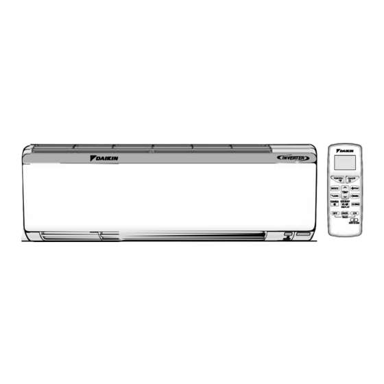
Read before Operation Name of Parts ■ Indoor Unit 1. Front panel 2.Air inlet 3. Air filter i _,a,1111 � 4. Accessory filter C �� 1 11111111 � 5. Model name plate 11111111 6. Indoor temperature sensor: • Detects the air temperature around the unit. 7.Display 8. -
Page 4: Remote Controller
■ Remote Controller 1. Signal transmitter: • Send signals to the indoor unit. �1 Display {LCD): ,,,DAIKIN • Displays the current setting. (In this illustration, each section is shown with its display on for the · ��-1,-: purpose of explanation.) --- =�... -
Page 5: Preparation Before Operation
Read before Operation Preparation before Operation CAUTION Incorrect handling of batteries can result in injury from battery leakage, rupturing or heating, or lead to equipment failure. Please observe the following precautions and use safely. • If the solution from the batteries should get in the eyes, do not rub the eyes. Instead, immediately flush the eyes with tap water and seek the attention of a medical professional. -
Page 6: Auto · Dry · Cool · Heat · Fan Operation
Operation AUTO • DRY• COOL • HEAT• FAN Operation The air conditioner operates with the operation mode of your choice. From the next time on, the air conditioner will operate with the same operation mode. ■ ■ To start operation To stop operation [t1/ 1 . - Page 7 Operation Adjusting Airflow Rate /SMELL PROOF/CHILD LOCK operation Adjusting the airflow rate You can adjust the airflow rate to increase your comfort. ■ To change the airflow rate setting . • Press [ ota F A � Each pressing of l+F A :;i changes the airflow rate setting in sequence. D----EJ----D- - - --- �...
- Page 8 You can adjust the airflow direction to increase your comfort. � CAUTION------------------ • Always use a remote controller to adjust the angles of the flaps. Moving the flaps forcibly by hand may cause a malfunction. • Be careful when adjusting the louvres. Inside the air outlet, a fan is rotating at a high speed. ■...
- Page 9 ration COANDA Operation The flow of air will be in the upward direction which will provide a comfortable air that will not come in direct contact with people. ■ To start COANDA operation COANDA J • 1. Press [ 'i' •...
- Page 10 Checking the Inverter Output and Temperature Display •□ When "Good Sleep/Display" key of remote controller push down and hold it for 2 second then "DISPLAY" IR Signal will be transmitted. • The inverter output and temperature display for the indoor unit shows the current inverter output, indoor temperature, and set temperature.
- Page 11 Operation Timer/ ECONO Operation Timer functions are useful for automatically switching the air conditioner on or off at night or in the morning. You can also use GOOD SLEEP OFF TIMER and ON TIMER in combination. ■ To cancel TIMER operation TIMER Operation ■...
- Page 12 Operation LED/ 7 SEGMENT BRIGHTNESS Control Operation The brightness of the indicator lamp/ 7 Segment can be adjusted H(high), L(low), or OFF. To set the brightness setting mode. ■ Press(<:�swlNoJ for more than 5 second's. • is displayed on the LCD. ■...
-
Page 13: Care And Cleaning
Care Care and Cleaning Before cleaning, be sure to stop the operation and � CAUTION turn off the circuit breaker. Units I ■ Indoor unit and remote controller 1. Wipe them with a dry soft cloth. ■ Front panel 1. Open the front panel. •... -
Page 14: Air Filter
Care Care and Cleaning &CAUTION • Do not touch the aluminium fins of the indoor unit. If you touch those parts, this may cause an injury. • When removing or attaching the front panel, use a robust and stable stool and watch your steps carefully. •... -
Page 15: Before A Long Idle Period
Care Care and Cleaning 1. Take off the filter. 2. Vacuum dusts, and soak in lukewarm water for about 10 to 15 minutes if dirt is heavy. • Do not remove the filter from frame when washing with water. 3. After washing, shake off remaining water and dry in the shade. •... -
Page 16: Troubleshooting
Troubleshooting Troubleshooting These cases are not problems The following cases are not air conditioner troubles but have some reasons. You may just continue using it. Case Explanation The air conditioner stops • Once the set temperature is reached, the airflow rate is reduced and generating airflow during HEAT operation stopped in order to avoid generating a cool airflow. -
Page 17: Check Again
Troubleshooting Troubleshooting Case Explanation The indoor unit gives out • This happens when smells of the room, furniture, or cigarettes are odour. absorbed into the unit and discharged with the airflow. (If this happens, we recommend you to have the indoor unit washed by a technician. - Page 18 ■ Troubleshooting Troubleshooting Call your service centre immediately & WARNING--------------- ■ when an abnormality (such as a burning smell} occurs, stop operation and turn off the circuit breaker. Continued operation in an abnormal condition may result in problems, electric shock or fire. Consult your service centre.
- Page 19 • A short beep indicates non-corresponding codes. • To cancel the code display, hold down (cANcaJ for 5 seconds. The code display also cancels itself if the button is not pressed for 1 minute. DAIKIN INDUSTRIES, LTD. Head office: Osaka Umeda Twin Towers South...
-
Page 21: Pump Down Operation
TRAIL OPERATION AND TESTING 1. Trial operation and testing • Check that the inter-unit wire is correctly connected. • Trial operation should be carried out in COOL operation. 1-1 Measure the supply voltage and make sure that it is within the specified range. 1-2 Select the lowest programmable temperature. -
Page 22: Outdoor Unit
OUTDOOR UNIT PURGING AIR AND CHECKING GAS LEAKAGE � WARNING ------------------------ • Do not mix any substance other than the specified refrigerant (R32) into the refrigeration cycle. • When refrigerant gas leaks occur, ventilate the room as soon and as much as possible. •... -
Page 23: Installing The Outdoor Unit
OUTDOOR UNIT INSTALLING THE OUTDOOR UNIT • When installing the outdoor unit, refer to "Precautions for Selecting a Location" and the "Outdoor Unit Installation Diagram". l'..111 FLARING THE PIPE END Lt_ WARNING C<rt e><act ' fal ��Remove burrs. � Incomplete flaring may result refrigerant gas leakage. Set exactly at the position shown below-. -
Page 24: Installation Tips
■ ■ ■ ■ ■ INSTALLATION TIPS Installing and Removing the indoor unit. � CAUTION---------- • Installation method 1> Push up. Be sure to wear protection gloves. Hook the claws of the bottom frame to the mounting plate. If the claws are difficult to hook, remove the front grille. •... -
Page 25: Indoor/Outdoor Unit Installation Diagram
INDOOR/OUTDOOR UNIT INSTALLATION DIAGRAM • The mounting plate should be installed on a wall which can support the weight of the indoor unit. ·:f .,.--_.. - @Moontingpl a tefodngscrewM4�25L(Jpc:s.) �oonlingplateflxlng.,,rewM4":2Ii(7pcs.) For type (i)@@@) (Refer table no. 2) For type@ (Refer table no. 3) Note: Before installation, mounting plate size shape must be matched with mounting plate available in the unit, then accordingly follow the installation instruction. - Page 26 BINDING OF INSULATION PIPE 1. The slit direction should be upward. 2. It should be sealed with vinyl tape without any gap. 3. Do not over tighten with vinyl tape. '" h1 ... rioo1 V�lap• � Wrap vinyl tape with the slit of the heat insulation pipe cover facing up so that there are no gap . If there is a gap or if it is tightened too much, it may cause condensation or water dripping.
-
Page 27: Indoor Unit
INDOOR UNIT WIRING 1) Strip wire ends (15mm). Terminal block 2) Match wire colours with terminal numbers on indoor and outdoor unit's terminal blocks and firmly screw wires to the corresponding terminals with the screw. 3) Connect the earth wires to the corresponding terminals. Attach the earth wire so that it is not connected to the fan motor connector. -
Page 28: Installing The Indoor Unit
INDOOR UNIT INSTALLING THE INDOOR UNIT ( Right-Side, Right-Back or Right-Bottom Piping) Open the front panel, open the Front grille (If Required), then open the service lid.(Refer to Installation Tips.) @Mounting plate Shape the refrigerant pipes. Refr i gerant pipes Pass the drain hose and refrigerant pipes through the wall hole. -
Page 29: Installing The Mounting Plate
INDOOR UNIT INSTALLING THE MOUNTING PLATE • The mounting plate should be installed on a wall which can support the weight of the indoor unit. 1) Temporarily secure the mounting plate to the wall, make sure that the panel is completely level, and mark the boring points on the wall. -
Page 30: Precautions For Selecting A Location
Accessories ® ~ ® Remarks Remarks ITEM ITEM QTY. QTY. ® Mountina plate ® Remote controller holder fixina screw (M3 x 20L @ Mountina elate fixina screw (M4 x 25L) CO 4-Core wire (3. 7M) 6/7" © Wireless Remote Controller (M) Tiewrap @ Dry battery (AAA) ®... - Page 31 SAFETY PRECAUTIONS • The precautions described herein are classified as WARNING and CAUTION. They both contain important information regarding safety. Be sure to observe all precautions without fail. • Meaning of WARNING and CAUTION notices � WARNING Failure to follow these instructions properly may result in personal injury or loss of life. �...
- Page 32 3P665364-2T M21 P076C DAIKIN ROOM AIR CONDITIONER INSTALLATION MANUAL C..JNVERTER> �� � �I.P' �8�1 �E'� �'=:� MODELS: FTHT35UV16W FTHT50UV16V FTHT60UV16U 3P665364-2T M21 P076C FTHP50UV16U...