Table of Contents
Advertisement
Quick Links
EB 7030 EN
Translation of original instructions
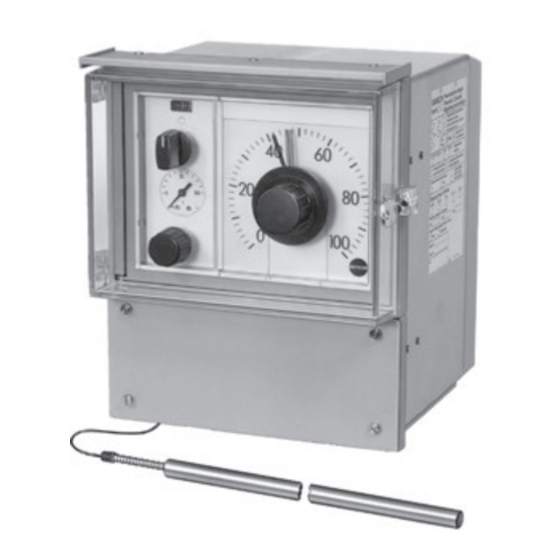
Type 3432 Controller Station
- with Type 3435 Transmitter Module for pressure
- with Type 3436 Transmitter Module for temperature
- with Type 3438 Transmitter Module for temperature (Pt 100)
- for standardized signals
The version with lockable door and installed Type 3436
Transmitter Module for temperature is shown.
Type 3430 Pneumatic Indicating Controllers
Series 430
Edition May 2018
Type 3431 Controller Station
- for standardized signals
Advertisement
Table of Contents

Related Manuals for Samson 430 Series


Summary of Contents for Samson 430 Series
- Page 1 EB 7030 EN Translation of original instructions Type 3432 Controller Station Type 3431 Controller Station - with Type 3435 Transmitter Module for pressure - for standardized signals - with Type 3436 Transmitter Module for temperature - with Type 3438 Transmitter Module for temperature (Pt 100) - for standardized signals The version with lockable door and installed Type 3436 Transmitter Module for temperature is shown.
- Page 2 WARNING! Damage to health relating to the REACH regulation. If a SAMSON device contains a substance which is listed as being a substance of very high concern on the candidate list of the REACH regulation, this circumstance is indicated on the SAMSON delivery note.
-
Page 3: Table Of Contents
Contents General safety instructions ................5 Application ....................6 Operation .....................6 Settings at the controller modules ..............6 3.1.1 Direction of action ..................6 3.1.2 Air output capacity ..................7 3.1.3 Proportional-action coefficient KP ..............8 3.1.4 Reset time Tn ....................8 3.1.5 Derivative-action time Tv .................8 3.1.6 Operating point .....................8 Adjusting the limit contacts ................9... - Page 4 Contents Connections ....................36 Pneumatic connections..................36 7.1.1 Connection examples ...................36 7.1.2 Adjusting the supply air in supply pressure regulators ........37 Electrical connections ...................38 Maintenance ....................40 Checking the air supply ................40 Conversion ....................41 Changing the controller function ..............41 Exchanging the transmitter module ..............44 Checking the controller function ..............44 Use in hazardous areas ................45 10.1...
-
Page 5: General Safety Instructions
General safety instructions General safety instructions − The device must be mounted, started up or serviced by fully trained and qualified personnel only; the accepted industry codes and practices are to be observed. Make sure employees or third persons are not exposed to any danger. -
Page 6: Application
Application Application 3.1.1 Direction of action The Series 430 Pneumatic Controllers are The direction of action for the control loop is used for the automation of process and in- set at the turnboard A, where the position of dustrial plants. its arrow symbol according to the arrow symbol on the controller module determines The controllers measure directly the the direction of action of the controller... -
Page 7: Air Output Capacity
Operation 3.1.2 Air output capacity yA Normal air delivery Approx. 1 m ³/h per % of the system (Type 3433 Controller Module only) deviation The position of turnboard B (Fig. 1) with its High air delivery R arrow symbol determines the air delivery to approx. -
Page 8: Proportional-Action Coefficient Kp
Operation 3.1.5 Derivative-action time Tv Î Undo screws (3.3) and pull off the connecting plate (3.2) together with Controller versions with derivative-action square nuts and bolts from the controller component require the derivative-action time module. Tv to be set at the adjuster (11). The setting Î... -
Page 9: Adjusting The Limit Contacts
Operation 3.2 Adjusting the limit contacts Only with controller station that have the op- tional inductive limit contacts. Before adjustment, release the lock (4, Fig. 1) and open the indicating unit (5). The contacts can be accessed on the back of the device. -
Page 10: Start-Up And Settings
Start-up and settings Start-up and settings Before start-up of the control loop, check all devices to make sure that they are connected correctly, do not leak and function properly. Release the lock (4) and open the indicating unit (5) to access the operating controls on the controller. -
Page 11: Adjusting The Operating Point In P And Pd Controllers
Start-up and settings 5. Briefly set the Tn restrictor to its minimum Should oscillations still occur despite these setting (fully open) to allow the red con- settings, slightly reduce Kp and increase Tn. trolled variable pointer to move to the Repeat these steps, if necessary, until the green set point pointer. -
Page 12: Bumpless Automatic/Manual Mode Changeover
Start-up and settings Do not set the switch (1.6) to automatic until Note the differential pressure indicator (1.8) reads If a P/PI controller is switched to P action, zero. completely open the Tn restrictor to ensure Afterwards, adjust the set point again to the the operating point adjuster can take effect required value. -
Page 13: Design And Principle Of Operation
Design and principle of operation Design and principle of For use as combined fixed set point and fol- lower controller, the controller station is fitted operation with an additional unit for w switcho- The modular controllers represent a complete ver; for use as a follower controller with an automation package consisting of a control- additional pneumatic or electric input for ex- ler station, a controller module suitable for... -
Page 14: Transmitter Modules
Design and principle of operation 5.1 Transmitter modules Type 3438 for temperature with Pt 100 resistance thermometer Type 3435 for pressure The Type 3438 Transmitter Module consists The pressure p of the process medium is fed of an electric transmitter and a downstream to the transmitter module (2) where it creates i/p converter for connection to a Pt 100 a movement at the bourdon tube measuring resistance thermometer. - Page 15 Design and principle of operation 1.41 1.4 1.3 1.41 1.4 1.3 P PI P PI 2.9 2.8 Type 3432 with Type 3435 Pneumatic Transmitter Type 3432 with Type 3436 Transmitter for for pressure temperature 1.2 1.4 1.3 1.41 1.4 1.3 P PI P PI Type 3432 with manual/automatic switch (1.6), Type 3431 and Type 3432 for pneumatic supply pressure regulator (1.9) and i/p converter...
-
Page 16: Controller Station
Design and principle of operation 5.2 Controller station 5.3 Controller modules The controlled variable signal x produces a The controller modules are plug-in units. deflection on the bellows measuring system They are plugged into the self-sealing sockets of the controlled variable display (1.3) which of the controller station and held by a fasten- is transmitted to the pointer over a gear ing screw. - Page 17 Design and principle of operation assumes a value corresponding to the controlled variable x and the adjusted pro- portional-action coefficient Kp adjustable over a screw. Outside of the controller module, the y connected to R, allowing the output pressure to be fed back to bellows R1 also over the port R and the adjustable Tn restrictor.
- Page 18 Design and principle of operation Type 3433-2 PI Controller Module The following controller module versions are almost identical to the Type 3433-2 PI Con- troller Module, except they are fitted with, for example an operating point adjuster, a de- rivative element or a selector switch, de- pending on the application.
- Page 19 Design and principle of operation Type 3433-4 PD Controller Module This module is largely identical to the Type 3433-1. However, it contains a deriva- tive element providing a rate gain of the in- put branch of the controlled variable x. It has a derivative-action gain of approx.
-
Page 20: Type 3434 Controller Module
Design and principle of operation 5.3.2 Type 3434 Controller The pressures acting in the diaphragm cham- bers R1 and R2 equal each other. Module The position of the force switch changes until The controller modules feature a box-shaped the controller output pressure assumes a val- comparator that operates according to the ue assigned to the controlled variable x and force-balance method. -
Page 21: Diaphragm Seal
Design and principle of operation 5.4.1 Mounting with diaphragm Type 3434-1 P Controller Module The design and principle of operation are al- seal most identical to that of the Type 3434-2 PI Controller Module. However, the feedback On using the Type 3430 Pneumatic Indicat- element with Tn restrictor is replaced by a ing Controller with diaphragm seal, observe spring for fixed operating point adjustment... -
Page 22: Diaphragm Seal For General Use
Design and principle of operation 5.4.2 Diaphragm seals for gen- Note eral use The diaphragm seal has been cleaned and assembled under special conditions. The See Fig. 9 process fluid connection must not come into The diaphragm seal in the version for gener- contact with oil or grease during installation. - Page 23 Design and principle of operation On installing the Type 3430 Pneumatic Indi- NOTICE cating Controller with diaphragm seal, ob- For use with flammable gases, observe the serve the following points: following: Î To prevent gas migration into another − In potentially explosive atmospheres, the zone, the attachment of the diaphragm ambient temperature must not exceed seal to the process must meet stringent...
- Page 24 Design and principle of operation Table 1: Diaphragm seals for general use, use with oxygen or flammable gases Diaphragm seal for … General use Gaseous oxygen Flammable gases Measuring ranges up to Compliant with 25 bar NACE MR 0175 Top and bottom Top and bottom Top and bottom sections sections fastened sections, diaphragm...
-
Page 25: Additional Units
Design and principle of operation 5.5 Additional units 5.5.1 Type 6112 i/p Converter External set point w and/or controlled variable x can be provided by a current sig- nal from 0/4 to 20 mA or 1 to 5 mA and converted into the pneumatic standardized signal from 0.2 to 1 bar by the i/p convert- Connecting plate with two i/p converters for controlled variable x and external set point... -
Page 26: Inductive Limit Contacts
Installation 5.5.4 Inductive limit contacts Installation The inductive limit contacts indicate when the 6.1 Mounting controlled variable x falls below and/or ex- ceeds an adjustable limit. Installation and connections The indicator shaft of the controlled variable The following types of mounting in Table 2 x is fitted with two adjustable metal tags, are possible (see Fig. 13 and Fig. 17): which operate the associated proximity... - Page 27 Installation Table 2: Types of mounting Pipe mounting With mounting part and clamp for mounting to a vertical or horizontal 2” pipe Mounting kit: order no. 1400-6302 Wall mounting With three brackets for attachment to a wall Mounting kit order no.: 1400-6301 Panel mounting With four fastening elements (IEC 61554) for attachment to the control panel Distance between center lines with door approx.
- Page 28 Installation Pipe mounting Protective roof Mounting plate order no.: 1400-6311 Clamp 2” pipe M20x1.5 Cable gland for i/p converter ), limit contacts Wall mounting Pneumatic connections Process fluid Tapped holes connection ISO 228/1-G i/p converter (w limit contacts Connections Dimensions of Type 3430 Indicating Controller for pressure Ext.
- Page 29 Installation Pipe mounting Protective roof Bulb sensor Mounting plate order no.: 1400-6311 Active sensor length Air sensor Clamp Ø19,5 Ø12 2” pipe G¾ 30 30 30 30 Cable gland M20x1.5 i/p converter (w ), limit contacts Wall mounting Ø7 Ø7 Pneumatic connections Tapped holes Sensor connection...
- Page 30 Installation Pipe mounting Accessories: protective roof Order no.: 1400-6311 Mounting plate Clamp 2” pipe 30 30 Pt100 Cable glands 2” pipe 24 V M20x1.5 Accessories: protective roof Wall mounting Order no.: 1400-6311 Ø7 i/p converter (w Pt100 limit contacts, air con- Cable glands nections behind them M20x1.5...
- Page 31 Installation Pipe mounting Accessories: protective roof Order no.: 1400-6311 Mounting plate Clamp 2” pipe 30 30 30 2” pipe Cable gland M20x1.5 Electrical connections for i/p con- verter (x and w ) and limit contacts Wall mounting Ø 7 Pneumatic connections Tapped holes ISO 228/1-G ...
- Page 32 Installation Pipe or wall mounting Accessories: protective roof Order no.: 1400-6311 Electrical Pneumatic connections connections 4 to 20 mA Version with converter module Dimensions of Type 3430 Indicating Controller for stan- Connections dardized signals Controlled variable Type 3432 Controller Station Ext. set point Pipe and wall mounting, 8/9 Z Supply air...
-
Page 33: Changing Scales
Installation 6.1.1 Changing scales 6.2 Installing the temperature sensor After releasing the lock (4, Fig. 3), the scale can be pulled out of the back of the indicat- Controller station with Type 3436 Transmit- ing unit and replaced with a special scale, if ter Module only necessary. - Page 34 Installation Fastening parts for bulb sensor d = 12 mm, 425 mm long, active length 300 mm All wetted parts of the screw gland and thermowell are made of stainless steel 1.4404/1.4571 Clamping flange Ø50 for wall mounting, e.g. depressurized tanks, ducts etc. Order no.: 1090-9547 Fasten the flange with two screws to the side and fasten the temperature sensor using two other screws in the flange.
- Page 35 Installation Weld-in thermowell (PN 63) SW 32 Order no.: 1080-4890 Thermowell with flange DN 25 (PN 40, PN 100) Order no.: 1080-4891 (PN 40) 1080-4892 (PN 100) SW 32 Fig. 18: Dimensions · Mounting parts for bulb sensor EB 7030 EN...
-
Page 36: Connections
Connections Connections Port open in controllers for standardized sig- nals. 7.1 Pneumatic connections 7.1.1 Connection examples The pneumatic connections on the bottom of the device are designed as bores with ISO 228/1-G thread. Customary fittings for tubing or plastic hoses can be used. NOTICE The supply air is dry as well as free of oil 0,2...1 bar... -
Page 37: Adjusting The Supply Air In Supply Pressure Regulators
Connections 7.1.2 Adjusting the supply air in supply pressure regula- tors Only with Type 3432 Controller Station with pressure controllers Hose connections for supply air, which are sealed by end caps, are located directly across the corners of the pressure controller on the bridge of the connecting plate (inside of the housing). -
Page 38: Electrical Connections
Connections 7.2 Electrical connections WARNING Electrical connection only applies to the con- Incorrect electrical connection will render the troller stations with additional i/p converter explosion protection unsafe. for controlled variable x, external set point Do not loosen enameled screws in or on the housing. - Page 39 Connections Installation, wiring, terminals, cable entries and other components that are relevant to Type 3432 explosion protection comply with EN 60079- Controller Station 0, EN 60079-11 and EN 60079-14 12 11 21 22 42 41 52 51 (IEC 60079-14). EN 60079-14 Explosive – + + – –...
-
Page 40: Maintenance
Maintenance Maintenance These two filters cannot be renewed. In addition, the pneumatic connections on the bottom of the housing have filters with 8.1 Checking the air supply plastic rims (order no. 0550-0189) which The modules of the pneumatic controller are can be removed for cleaning. -
Page 41: Conversion
Conversion Conversion P to PID: Same as for P to PD. In addition, replace adjuster (12) with Tn restrictor (10). P controller with set-point-dependent operat- 9.1 Changing the controller ing point function The controller function can either be changed Attach plate with restriction (15) in place of by exchanging the entire module the adjuster for operating point (12). - Page 42 Conversion P to PI P to P/PI 14.1, 14.2 11.1, 11.2 P to PD, PI to PID (15) (15) 14.1, 14.2 11.1, 11.2 Filter Restriction (7) Seals in P and PI Seals in PD and PID controllers controllers 14.4 10.2 14.3 14.4 10.2...
- Page 43 Conversion Table 3: Spare parts Part Qty. Designation Order no. Restriction with filter 1390-0183 Tn restrictor 1070-4584 10.1 M3 x 8 screws 8333-0479 10.2 O-rings 1.78 x 1.02 8421-0010 Tv restrictor 1070-4585 11.1 Cover plate 0360-1597 11.2 M3 x 8 screws 8333-0479 11.3 O-rings 2 x 1.5 8421-0023 Operating point adjuster 1.4 bar 1070-7550 Operating point adjuster 20 psi 1070-7551...
-
Page 44: Exchanging The Transmitter Module
Controlled variable Hose grommet Contact SAMSON to order the new module specifying the sensor version and required Supply air Z measuring range. Also specify the data writ- Fig. 24: Connecting plate ten on the nameplate of the old transmitter module. -
Page 45: Use In Hazardous Areas
Use in hazardous areas Use in hazardous areas Conditions for use in hazardous areas: − The control station is not labeled with the The Type 3430 Controller is suitable for use associated mark of approval for explo- in hazardous areas of Zone 1 and 2 without sion-protected equipment. -
Page 46: Servicing Explosion-Protected Devices
Armaturenbau GmbH, Adapt-FS, device must not be put back into operation PTB 12 ATEX 4001 X (SAMSON order until a qualified inspector has assessed it ac- no. 8521-1002). Special conditions of cording to explosion protection require-... -
Page 47: Technical Data
Technical data Technical data Type 3432 and Type 3431 Controller Stations Controlled variable Measuring range 0.2 to 1.0 bar (3 to 15 psi) · Accuracy class 1.6 · Scale length 212 mm display Set point adjustment Output 0.2 to 1.0 bar (3 to 15 psi) · Scale length 212 mm · Accuracy class 1.6 Adjuster for manual Output 0.2 to 1.0 bar (3 to 15 psi) ·... - Page 48 Technical data Pressure Equipment 2014/68/EU, Article 4.3 (sound engineering practice) Directive Total weight (approx.) 6 kg Type 3435 Transmitter Module Measuring range (set 0 to 1.6 · 0 to 2.5 · 0 to 4.0 · 0 to 6.0 · 0 to 10 · 0 to 16 · 0 to 25 · 0 to 40 point range) in bar Overloadable up to ...
- Page 49 Technical data i/p converter module No explosion Type 6112-02 Input impedance 200 Ω and ~5.9 mH protection With explosion Type 6112-22 Intrinsically safe input current circuit · Input impedance 200 Ω and ~0 mH 1) 1) protection Ex II 2G Ex ia IIC T6 Gb according to EC type examination certificate Explosion protection PTB 00 ATEX 2021 Input...
- Page 50 Technical data Type 3438 Transmitter Module Type 3438 · General specifications Design Type 3438 consisting of the interconnection of TTH200-E1H temperature transmitter with Type 6112-22 i/p Module Pt 100 resistance thermometer (RTD), DIN EN 60751 · Four-wire circuit, line Sensor resistance <50 Ω Input –30 to 60 °C, 0 to 40 °C, 0 to 100 °C, 0 to 150 °C, 0 to 200 °C, 0 to 400 °C, Measuring ranges others on request Pneumatic...
-
Page 51: Certificates
Certificates Certificates The ATEX certificates are included on the next pages. EB 7030 EN... - Page 52 EB 7030 EN...
- Page 53 EB 7030 EN...
- Page 54 EB 7030 EN...
- Page 55 EB 7030 EN...
- Page 56 EB 7030 EN...
- Page 57 EB 7030 EN...
- Page 58 EB 7030 EN...
- Page 59 EB 7030 EN...
- Page 60 EB 7030 EN...
- Page 61 EB 7030 EN...
- Page 62 EB 7030 EN...
- Page 63 EB 7030 EN...
- Page 64 EB 7030 EN...
- Page 65 EB 7030 EN...
- Page 66 EB 7030 EN...
- Page 67 EB 7030 EN...
- Page 68 EB 7030 EN...
- Page 69 EB 7030 EN...
- Page 70 EB 7030 EN...
- Page 71 EB 7030 EN...
- Page 72 EB 7030 EN...
- Page 73 EB 7030 EN...
- Page 74 EB 7030 EN...
- Page 75 EB 7030 EN...
- Page 76 EB 7030 EN...
- Page 77 EB 7030 EN...
- Page 78 EB 7030 EN SAMSON AKTIENGESELLSCHAFT Weismüllerstraße 3 · 60314 Frankfurt am Main, Germany Phone: +49 69 4009-0 · Fax: +49 69 4009-1507 samson@samson.de · www.samson.de...