Samson 4765 Mounting And Operating Instructions
Pneumatic positioner
Hide thumbs
Also See for 4765:
- Mounting and operating instructions (25 pages) ,
- Mounting and operating instructions (32 pages)

Related Manuals for Samson 4765


Summary of Contents for Samson 4765
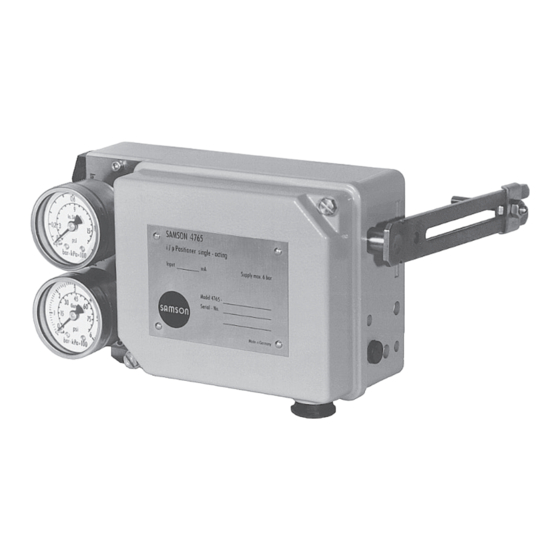
- Page 1 Type 4765 Pneumatic Positioner Type 4765 Pneumatic Positioner Mounting and Operating Instructions EB 8359-1 EN Edition April 2014...
- Page 2 Definition of signal words DANGER! NOTICE Hazardous situations which, if not Property damage message or mal- avoided, will result in death or seri- function ous injury Note: WARNING! Additional information Hazardous situations which, if not avoided, could result in death or seri- Tip: ous injury Recommended action...
-
Page 3: Table Of Contents
Contents General safety instructions ................5 Article code ....................6 Technical data ....................7 Design and principle of operation ..............8 Attachment ....................10 Attachment to valve with cast yoke ..............10 Attachment to valve with rod-type yoke ............10 Housing cover .....................10 Pneumatic connections .................12 Pressure gauge ....................12 Supply pressure ...................12 Operation ....................13 Assignment of the positioner and the actuator ..........13... -
Page 5: General Safety Instructions
General safety instructions 1 General safety instructions For your own safety, follow these instructions concerning the mounting, start-up and opera- tion of the positioner: − The positioner is to be mounted, started up or operated only by trained and experienced personnel familiar with the product. -
Page 6: Article Code
Article code 2 Article code Pneumatic positioner Type 4765- 0 Spring Spring 1, travel = 15 mm Spring 2, travel = 30 mm, split range 15 mm Spring 3, travel = 60 mm, split range 30 mm Pneumatic connections ISO 228/1 G ¼... -
Page 7: Technical Data
Technical data 3 Technical data Controlled variable (travel range) 7.5 to 60 mm, with lever extension: 7.5 to 90 mm Reference variable 0.2 to 1 bar (3 to 15 psi) Split-range 0 to 50 % or 50 to 100 % 0.2 to 0.6 bar (3 to 9 psi) and 0.6 to 1 bar (9 to 15 psi) reference variable span (up to 50 mm travel) Range spring... -
Page 8: Design And Principle Of Operation
Design and principle of operation 4 Design and principle of oper- Any change in the control signal p or the valve position causes the pressure to change ation upstream or downstream of the booster. The The pneumatic positioner is used to assign air controlled by the booster (signal pressure the valve position (controlled variable) to the ) flows through the volume restriction (14) - Page 9 Design and principle of operation 6.1 6 10.2 Fig. 1: Positioner (opened) 2 2.1 Travel 10.2 Arrangement of nozzle/ flapper plate for reverse 10.1 <> operating direction p st Output 36 12.2 10.1 Supply 9 Input Fig. 2: Functional diagram EB 8359-1 EN...
-
Page 10: Attachment
Attachment 5 Attachment 5.2 Attachment to valve with rod-type yoke To attach the positioner to valves with cast yokes), mounting parts (order no. 1400- 1. Fasten the plate (20), off-centered, to the 5745) are used. For valves with rod-type travel indicator (24) of the plug stem (23) yokes (pillars), the mounting kit (order no. - Page 11 Attachment 22 23 Fig. 3: Attachment to valves with cast yokes (NAMUR rib) 20 2.1 Fig. 4: Attachment to valves with rod-type yokes EB 8359-1 EN...
-
Page 12: Pneumatic Connections
Pneumatic connections 6 Pneumatic connections Actuator stem extends (FA) Fail-close The pneumatic connections are optionally (for globe and angle valves) designed as a bore with NPT or ISO 288/1- Required supply pressure = G thread. Upper bench range value + 0.2 bar, Customary fittings for metal or copper tubing minimum 1.4 bar or plastic hoses can be used. -
Page 13: Operation
Operation 7 Operation tends” to “actuator stem retracts” or vice ver- sa, the positioner's mounting position must 7.1 Assignment of the posi- be changed accordingly. tioner and the actuator Arrangement of the actuator, the mounting position of the positioner, the reference vari- able and the operating direction: Î... -
Page 14: Determining And Changing The Operating Direction
Operation 7.1.1 Determining and versed "plate on top of lever" is correct (Fig. 5 to Fig. 8). changing the operating direction For an increasing input signal (reference variable), the signal pressure p can either be increasing (direct action <<) or decreas- ing (reverse action <>). Similarly, as the reference variable decreas- es, the signal pressure can either decrease (direct action <<) or increase (reverse action... - Page 15 Operation Operating direction increasing/increasing (direct <<) Operating direction increasing/decreasing feeler pin on top of flapper plate (reverse <>) flapper plate on top of feeler pin Range spring Cover plate Nozzle block Feeler pin Marking Flapper Fig. 9: Position of nozzle block, cover plate removed Travel Travel Valve 2...
-
Page 16: Starting Point And Reference Variable
Operation 7.2 Starting point and refer- 7.3 Adjustment after mounting ence variable the positioner on the valve Connect the control signal input to a com- The attached lever and the installed range pressed air source of max. 1.5 bar using a spring of the positioner are assigned to the remote adjuster and a pressure gauge. - Page 17 Fig. 12: Setting the Xp restriction Table 1: Range springs Rated travel [mm] Min./max. travel [mm] Reference variable (input signal) Range spring Standard travels for SAMSON valves with lever l (40 to 127 mm in length) 100 % 7.5 to 15 50 % 100 % 14 to 32 50 %...
-
Page 18: Setting For Actuator With Fail-Safe Action "Stem Extends
Operation 7.3.2 Setting for actuator with After correcting the input signal, re-ad- just zero. Then check the upper range fail-safe action “stem ex- value again. tends” Repeat the correction procedure until both To ensure that the total closing force of the values are correct. -
Page 19: Exchanging The Range Spring
Operation 2. Increase the input signal and slowly re- 2. Exchange range spring. Slide lever with duce it again to 1 bar. Check whether shaft through sleeve (3), positioner hous- the valve starts to move at exactly ing and bracket (6.1). 0.1 bar. -
Page 20: Upgrading The Pneumatic Positioner
Note: gland (1) along with the seal. The version suitable for oxygen of the Type 4765 Pneumatic Positioner can- With Type 6112: not be converted to form a 1. Proceed as described in steps 1 and 2 of Type 4763 Electropneumatic Position- Type 6109... - Page 21 Upgrading the pneumatic positioner Type 6109 i/p Converter Type 6112 i/p Converter Fig. 13: Converting the positioner EB 8359-1 EN...
-
Page 22: Accessories, Mounting Parts And Conversion Kits
Accessories, mounting parts and conversion kits 9 Accessories, mounting parts and conversion kits Accessories – Mounting parts Order no. Range spring 1 1190-0736 Range spring 2 1190-0737 Range spring 3 1190-0738 Lever I 1690-6469 1400-6716 Lever extension Pressure gauge attachment, device index .02 and higher 1400-6718 Pressure gauge attachment, device index .03 and higher 1400-6950... -
Page 23: Dimensions In Mm
Dimensions in mm 10 Dimensions in mm tapped hole in housing with G threaded connection or NPT in housing with NPT threaded connection Useable lever length I: 40 to 127 mm (with lever extension 40 to 200 mm) Pneumatic connections: ISO-228/1-G ¼ or ¼-18 NPT EB 8359-1 EN... - Page 24 SAMSON AG · MESS- UND REGELTECHNIK Weismüllerstraße 3 · 60314 Frankfurt am Main, Germany Phone: +49 69 4009-0 · Fax: +49 69 4009-1507 EB 8359-1 EN samson@samson.de · www.samson.de...