Table of Contents
Advertisement
Quick Links
Digital Temperature Controllers
E5@Z
Compact and Intelligent
General-purpose Temperature
Controllers
• Various temperature inputs: thermocouple, platinum re-
sistance thermometer, infrared temperature sensor,
and analog inputs.
• Auto-tuning and self-tuning available. Auto-tuning is
possible even while self-tuning is being executed.
• Heating or heating/cooling control is available.
• Event input allows multi-SP selection and run/stop func-
tion.
• CE marking and UL/CSA certification.
(CE marking and UL/CSA certification are pending for
the E5EZ-PRR.)
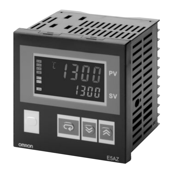
E5AZ
1/4 DIN
E5@Z Series
E5EZ
1/8 DIN
Contents
Digital Temperature Controllers
E5AZ ............................................................
E5EZ ............................................................
E5CZ ............................................................
E5EZ-PRR....................................................
Common to All Controllers
• Nomenclature ...............................................
• Operation......................................................
• Peripheral Devices .......................................
• Safety Precautions .......................................
E5CZ
E5EZ-PRR
1/16 DIN
2
7
12
29
17
19
28
52
Digital Temperature Controllers
Digital Position-
Proportional
Controller
1/8 DIN
E5@Z
®
1
Advertisement
Table of Contents

Related Manuals for Omron E5 Z Series


Summary of Contents for Omron E5 Z Series
- Page 1 Digital Temperature Controllers E5@Z Compact and Intelligent General-purpose Temperature Controllers • Various temperature inputs: thermocouple, platinum re- sistance thermometer, infrared temperature sensor, and analog inputs. • Auto-tuning and self-tuning available. Auto-tuning is possible even while self-tuning is being executed. • Heating or heating/cooling control is available. •...
-
Page 2: Model Number Structure
Digital Temperature Controllers E5AZ Next-generation Digital Temperature Controller • Depth of only 78 mm. • Various temperature inputs: thermocouple, platinum resistance thermometer, infrared temperature sensor, and analog inputs. • Auto-tuning and self-tuning are available. Auto-tuning is possi- ble even while self-tuning is being executed. •... -
Page 3: Ordering Information
Ordering Information ■ List of Models Size Power supply voltage Number of alarm Control outputs Model points 1/4 DIN 100 to 240 VAC Relay E5AZ-R3 96 × 96 × 78 mm (W × H × D) Voltage (for driving SSR) E5AZ-Q3 Current E5AZ-C3... - Page 4 ■ Input Ranges Platinum Resistance Thermometer Input Input type Pt100 JPt100 − 200 to − 199.9 to − 199.9 to Temperature 0.0 to 0.0 to 100.0°C range 850°C 500.0°C 500.0°C 100.0°C Setting number 0 Thermocouple Input Input type −200 to −20 to −100 to −20.0 to...
- Page 5 ■ Characteristics Indication accuracy Thermocouple: ( ± 0.5% of indicated value or ± 1 ° C, whichever is greater) ± 1 digit max. (See note 1.) Platinum resistance thermometer: ( ± 0.5% of indicated value or ± 1 ° C, whichever is greater) ± 1 digit max. Analog input: ±...
-
Page 6: Wiring Terminals
Dimensions Note: All units are in millimeters unless otherwise indicated. Group Mounted Mounted separately (96 × No. of units −3.5) +1.0 11.5 Recommended panel thickness is 1 to 8 mm. Group mounting is not possible in the vertica ALM1 direction. (Maintain the specified mounting space ALM2 ALM3 between Controllers when they are group... - Page 7 Digital Temperature Controllers E5EZ Next-generation Digital Temperature Controller • Depth of only 78 mm. • Various temperature inputs: thermocouple, platinum resistance thermometer, infrared temperature sensor, and analog inputs. • Auto-tuning and self-tuning are available. Auto-tuning is possi- ble even while self-tuning is being executed. •...
- Page 8 Ordering Information ■ List of Models Size Power supply voltage Number of alarm points Control outputs Model 1/8 DIN 100 to 240 VAC Relay E5EZ-R3 48 × 96 × 78 mm (W × H × D) Voltage E5EZ-Q3 (for driving SSR) Current E5EZ-C3 Additional control output...
- Page 9 ■ Input Ranges Platinum Resistance Thermometer Input Input type Pt100 JPt100 −200 to −199.9 to −199.9 to Temperature 0.0 to 0.0 to range 850°C 500.0°C 100.0°C 500.0°C 100.0°C Setting number 0 Thermocouple Input Input type −200 to −20 to −100 to −20.0 to −200 to −199.9 to...
- Page 10 ■ Characteristics Indication accuracy Thermocouple: ( ± 0.5% of indicated value or ± 1 ° C, whichever is greater) ± 1 digit max. (See note 1.) Platinum resistance thermometer: ( ± 0.5% of indicated value or ± 1 ° C, whichever is greater) ± 1 digit max. Analog input: ±...
- Page 11 Dimensions Note: All units are in millimeters unless otherwise indicated. Panel Cutouts Mounted separately Group Mounted (48 × No. of units −2.5) 11.5 Recommended panel thickness is 1 to 8 mm. ALM1 ALM2 ALM3 Group mounting is not possible in the vertical direction.
- Page 12 Digital Temperature Controllers E5CZ Next-generation Digital Temperature Controller • Depth of only 78 mm. • Various temperature inputs: thermocouple, platinum resistance thermometer, infrared temperature sensor, and analog inputs. • Auto-tuning and self-tuning are available. Auto-tuning is possi- ble even while self-tuning is being executed. •...
-
Page 13: Thermocouple Input
■ Accessories (Order Separately) Current Transformers (CTs) Model E54-CT1 E54-CT3 Hole diameter 5.8 dia. 12.0 dia. Specifications ■ Ratings Power supply voltage 100 to 240 VAC, 50/60 Hz 24 VAC/VDC, 50/60 Hz Operating voltage range 85% to 110% of rated supply voltage Power consumption 7 VA 5 VA, 3 W... -
Page 14: Analog Input
Analog Input Input type 0 to 50 mV Setting range Usable in the following ranges by scaling: −1999 to 9999 or −199.9 to 999.9 Setting number 21 Applicable standards by input type are as follows: K: GB/T 2814-98 J,L: GB/T 4994-98 T,U: GB/T 2903-98 E: GB/T 4993-98 N: GB/T 17615-98... -
Page 15: Current Transformers
Dimensions Note: All units are in millimeters unless otherwise indicated. Panel Cutouts Group Mounted Mounted separately (48 × No. of units −2.5) +1.0 +0.6 Recommended panel thickness is 1 to 8 mm. ALM1 Group mounting is not possible in the vertical direction. ALM2 OUT1 STOP... -
Page 16: Option Units
Wiring Terminals • The voltage output (control output) is not electrically insulated from the internal circuits. When using a grounded thermocouple, do not connect the control output terminals to the ground. If the control output terminals are connected to the ground, errors will occur in the measured temper- ature values as a result of leakage current. - Page 17 Nomenclature E5AZ No. 1 Display Operation Indicators Temperature Unit The temperature unit is displayed when the dis- 1. ALM1 (alarm 1) Displays the process value or param- play unit parameter is set to a temperature. In- Lights when the alarm 1 output is ON. eter type.
- Page 18 E5CZ No. 1 Display Temperature Unit Operation Indicators Displays the process value or parameter type. 1. ALM1 (alarm 1) The temperature unit is displayed when the dis- Lights when the alarm 1 output is play unit parameter is set to a temperature. Indi- cation is determined by the currently selected ALM2 (alarm 2) "temperature unit"...
-
Page 19: Operation
Operation PID Control Using Autotuning Typical Example Changing Parameters 4 T thermocouple −200 to 400°C Input type: Control method: PID control ST (self-tuning): OFF Calculate PID constants by AT (auto-tuning). Alarm type: 2 upper limit Alarm value 1: 30°C (For setting deviation) Set point: 150°C indicates that there is a pa-... - Page 20 ■ Specification Setting after Turning ON Power Outline of Operation Procedures Key Operation In the following descriptions, all the parameters are introduced in the display sequence. Some parameters may not be displayed depending on the protect settings and operation conditions. Power ON Operation level Adjustment level...
-
Page 21: Specification Setting After Turning On Power
Specification Setting after Turning ON Power Initial Setting Level Initial setting level This level is used for setting basic specifications of the Temperature Controller. Using this level, set the input type for selecting the input to be connected such as the thermocouple or platinum resistance ther- Input type mometer and set the range of set point and the alarm mode. -
Page 22: Input Type
Input Type When selecting the input type, follow the specifications listed in the following table. Specifications Set Value Input Temperature Range − 200 to 850 ( ° C)/ − 300 to 1500 ( ° F) Platinum resistance thermometer input Pt100 −... -
Page 23: Alarm Types
Alarm Types Select the alarm type from the 12 types listed in the following table. Set Value Alarm Type Alarm Output Operation When X is positive When X is negative Alarm function OFF Output OFF 1 (See note 1.) Upper- and lower-limit (deviation) (See note 2.) Upper-limit (deviation) Lower-limit (deviation) - Page 24 Parameters key 1 s min. Advanced Function Setting Level Parameters related to setting items for each level are marked in boxes in the flowcharts and brief descriptions are given as required. At the end of each setting item, press the mode key to return to the Resets to the default value.
-
Page 25: Input Shift
Power ON key 1 s min. key Less than 1 s Operation Level Initial Setting Level Adjustment Level key Less than 1 s key 3 s min. AT execute/cancel Add in the "additional Input type Process value PV display" parameter. Communications writing Process value/set point Scaling upper limit... -
Page 26: Protect Level
Protect Level Operation/adjustment protection Restricts displaying and modifying menus in operation, adjustment, and manual control levels. Initial setting/communications protection This protect level restricts movement to the initial setting, communications setting, and advanced function setting levels. Setting change protection Protects changes to setups by operating the front panel keys. -
Page 27: Troubleshooting
Communications Setting Level Set the E5AZ/E5EZ/E5CZ communications specifications in the communications setting level. For setting communications parameters, use the E5AZ/E5EZ/E5CZ panel. The communications parameters and their settings are listed in the following table. Parameter Displayed characters Set (monitor) value Set value Communications unit No. -
Page 28: Peripheral Devices
Peripheral Devices ■ Temperature Sensor / SSR Connection Example with SSR Temperature Controller Load Heater Voltage output terminal Load power (for driving SSR) Direct connection possible G3PB (Single-phase): 240 VAC 3 units (15 A, 25 A, 35 A, 45 A) 5 units (E5AZ/ E5AZ... -
Page 29: Unit Label
Digital Position-Proportional Controllers E5EZ-PRR A position proportional control model for the E5 Z-PRR series • Just 78mm depth • All types of input: temperature input type, analog (current, voltage) input type • Makes use of high-visibility LCD, with three lines of 4-digit display, for simplicity and clarity •... - Page 30 ■ Input Range • Thermocouples / Platinum Resistance Thermometer Platinum resistance ES1B Infrared Input Type Thermocouple Analog input thermometer temperature sensor Name Pt100 JPt100 0 to 50mV 70˚C 120˚C 165˚C 260˚C 1800 1800 1700 1700 Usable in the 1700 following ranges 1600 1500 by scaling:...
-
Page 31: Specifications
Specifications ■ Ratings Power supply voltage 100 to 240VAC, 50/60Hz Operating voltage range 85% to 110% of the designated source voltage Power consumption 10VA (10W) Sensor input Temperature input type Thermocouple: K, J, T, E, L, U, N, R, S,B Platinum Resistance Thermometer: Pt100,JPt100 Infrared temperature sensor: 10 to 70°C, 60 to 120°C, 115 to 165°C, 140 to 260°C Analog signal input: 0 to 50mV... - Page 32 Specifications ■ Characteristics Indication accuracy Thermocouple: (displayed value ± 0.5 % or ± 1°C, whichever is largest) ± 1 digit max. (see note 1) Platinum Resistance Thermometer: (displayed value ± 0.5 % or ± 1°C, whichever is largest) ± 1 digit max. Analog Input: ±...
-
Page 33: Package Content
Dimensions Note: All figures are in mm, unless otherwise stated. • Dimensions of Panel's Grooves ■ Main Unit Independent Installation Simultaneous Multiple Installations (Unit: mm) (Unit: mm) (48 Number of Units - 2.5) During installation, please insert a temperature gauge into During installation, please insert a temperature gauge into the grooves on the panel (thickness of 1 to 8 mm), and the grooves on the panel (thickness of 1 to 8 mm), and... - Page 34 Wiring Terminals • Standard insulation is applied to the temperature gauge's I/O sections. If reinforced insulation is required, connect the input and output terminals to a device without any exposed current-carrying parts, or to a device with standard insulation suitable for the maximum operation voltage of the power supply I/O section.
- Page 35 Nomenclature ■ E5EZ-PRR Temperature Unit The temperature unit is displayed when the display unit parameter is set to temperature. The value selected for the temperature units parameter determines the unit displayed. When set to ˚C, C is displayed, and when set to ˚F, F is displayed.
-
Page 36: Typical Example
Operation In the past, sensor input types, alarm types, and control time for controllers were set using the DIP switch. Now, these hardware settings can and M keys are used to switch between setting levels, with the level determined be performed with the parameters in the setting level. The by the amount of time the key is pressed. - Page 37 • Typical Example 2 Input type : 9T thermocouple -200˚C to 400˚C Control method : PID control Execute AT (auto-tuning) to calculate the PID constant Alarm 1 type : Upper limit of 2 Set value : 150˚C Setup steps Connect the Connect the power supply power supply Operation level...
- Page 38 ■ Setting Level Configuration and Panel Key Operations Parameters are split into groups, which are referred to as levels. Each of the set values (set items) in these levels are referred to as parameters. E5EZ-PRR parameters are categorized into the following 7 levels: Power ON Starting in manual mode Starting in automatic mode...
-
Page 39: Manual Control Level
■ Descriptions of Each Level • Protect Level • In order to switch to this level, it is necessary to press the M keys simultaneously for at least 3 seconds. This level is used to prevent unnecessary or accidental revisions to the parameters. The protected level is not displayed, so that no changes can be made to parameters within this level. - Page 40 ■ Setting the Type of Input Types of input include thermocouple, platinum resistance thermometer, infrared temperature sensor, and analog inputs. Please set your input type in accordance with the sensor to be used. Product spec- ifications also include multi input types, such as thermocouples/ plastic resistance thermometers, and analog input types, resulting in differences between set values.
-
Page 41: Alarm Output Operation
■ Alarm Types • The conditions of alarm output are jointly determined by Alarm Type and Alarm Hysteresis. • Below is an explanation of the alarm type, alarm value, upper alarm limit, and lower alarm limit parameters. Alarm output operation alt1 Type Alarm1... - Page 42 ■ Parameters Parameters related to setting items for each level are marked in boxes in the following flowchart and brief descriptions are given as required. After finishing each setting, press the mode key to return to the beginning of each level. Power ON Starting in manual mode Starting in automatic mode...
- Page 43 ■ Parameters • In each level, if you press the mode key on the final parameter, you will return to the parameter at the top of the level. Advanced function setting level Initial setting level init in-t Parameter initialization a 1lt Input type Alarm 1 latch l.ini...
- Page 44 Operation level Adjustment level Execute / cancel Stopped MV Hold: hold AT adjustment The "add process Process value value display" Open: open AT on: on l. a dj parameter must l. a dj Close: close AT off: off be on. PV error MV Communications writing cmwt...
- Page 45 ■ Operation/ Adjustment Protection Protect level The relationship between the set values and the range of protection is as shown below. oapt Operation / Set Values : Can be displayed/ changed adjustment protection Mode l.prt ❍ : Can be displayed ❍...
-
Page 46: Input Error
■ Trouble shooting When an error occurs, the main display alternately shows an error signal and the current item for display. This section explains how to inspect an error signal, as well as corresponding rectification measures. 5.err Input Error • Meaning The figure inputted has exceeded the designated input range (the designated range is between -1999 (-199.9) to 9999 (999.9)). -
Page 47: Memory Errors
S. Err indicator Value display S. Err indicator cccc indicator Value display S. Err indicator Input indicator range Input indicator range -1999 9999 -1999 Display range 9999 Display range (-199.9) (999.9) (-199.9) (999.9) S. Err indicator cccc indicator cccc indicator S. - Page 48 Ceramic Furnace Position Proportional Control Reading the extent of the valve's opening with a potentiometer, and using open and close tuning control is referred to as position proportional con- trol or on/ off servo control. ■ Examples of Application When using position proportional methods to control gas combustion furnace valves, position propor- tional control should be applied.
- Page 49 ■ Wiring Input should be connected to terminals 9, 10, and 11 depending upon input type. The Out 1 ter- minal links to the position proportional valve's open side and the Out 2 terminal links to its closed side. Ceramic kiln (combustion) CLOSE Sensor...
-
Page 50: Position Proportional Control
■ Adjustment For adjustments to PID, please execute AT. ■ Fixed Settings for After selecting position proportional control, it is possible to use closed/ floating, electro-mechanical calibration, travel time, position proportional dead band, Position Proportional switch hysteresis, potentiometer input error, and process value dead band. Control •... - Page 51 Meeting all of your temperature control needs in a wide range of applications ■ ES1B Infrared Temperature Sensor Perform measurements with a contract-free sensor at minimal costs! • Outputs electromotive forces identical to those of thermocouples, so that it can be connected directly to temperature controllers that gen- erally use thermocouple input.
-
Page 52: Safety Precautions
Safety Precautions Precautions for Safe Use !CAUTION Be sure to observe the following precautions to prevent operation Do not touch the terminals while power is being supplied. failure, malfunction, or adverse affects on the performance and Doing so may occasionally result in minor injury due to functions of the product. - Page 53 13.When inserting the Temperature Controller into the case, do not Precautions for Correct Use force it into the case. Doing so will damage internal parts. 14.The EEPROM has a limited write life. When overwriting data Service Life frequently, e.g., via communications, use RAM Mode. 15.Use the product within the rated load and power supply.
- Page 54 Mounting (E5AZ/E5EZ) Removing the Temperature Controller from the Case 1. Insert the E5AZ/E5EZ into the mounting hole in the panel from the front. To remove the Temperature Controller from case, use a suitable Phil- 2. Push the mounting bracket along the E5AZ/E5EZ body from the lips screwdriver for the screw located at the bottom on the front terminals up to the panel, and secure it temporarily.
-
Page 55: Precautions When Wiring
Setting Up Option Units (E5CZ) Precautions when Wiring • Separate input leads and power lines in order to prevent external If communications, event input, or heater burnout functions are noise. required, mount the E53-CNH03N/E53-CN03N Communications Unit or the E53-CNHBN/E53-CNBN Event Input Unit. The heater •... -
Page 56: Warranty And Application Considerations
CONTRACT, WARRANTY, NEGLIGENCE, OR STRICT LIABILITY. In no event shall the responsibility of OMRON for any act exceed the individual price of the product on which liability is asserted. IN NO EVENT SHALL OMRON BE RESPONSIBLE FOR WARRANTY, REPAIR, OR OTHER CLAIMS REGARDING THE...