Table of Contents
Advertisement
Quick Links
See also:
User Manual
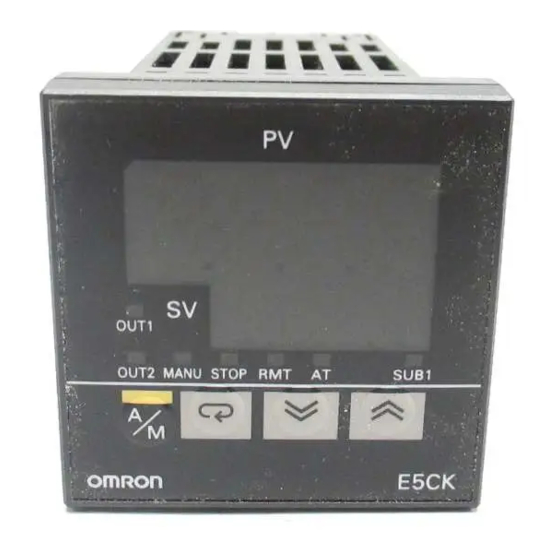
Digital Controller
E5CK
Advanced, Compact Digital Controllers
• IP66/NEMA4 (indoor use) front face.
• Modular structure, one-stock type.
• Heating/cooling control.
• Serial communications (RS-232C and RS-485).
• Temperature and analog inputs.
• High-accuracy: 100 ms sampling (for analog input).
• Advanced tuning which includes fuzzy self-tuning.
• Conforms to international EMC and safety standards.
• AC/DC24V types are also available.
Ordering Information
■ List of Models
Description
Base Unit
Note: A single Output Unit and Option Unit can be mounted to each Base Unit.
Description
Output Unit
Description
Option Unit
Inspection Report
The Digital Controller can be provided together with an inspection report.
Refer to the following legend with the suffix "K" when ordering a model provided together with an inspection report.
E5CK-AA1-K, E53-CKF-K
■ Accessories (Order Separately)
Name
Terminal Cover
E5CK-AA1 AC100-240
E5CK-AA1-500 AC100-240
E5CK-AA1 AC/DC24
E5CK-AA1-500 AC/DC24
E53-R4R4
E53-Q4R4
E53-Q4HR4
E53-C4R4
E53-C4DR4
E53-V44R4
E53-Q4Q4
E53-Q4HQ4H
E53-CK01
E53-CK03
E53-CKB
E53-CKF
Model
E53-COV07
Model
Base Unit
Base Unit with terminal cover
Base Unit
Base Unit with terminal cover
Model
Relay/Relay
Pulse (NPN)/Relay
Pulse (PNP)/Relay
Linear (4 to 20 mA)/Relay
Linear (0 to 20 mA)/Relay
Linear (0 to 10 V)/Relay
Pulse (NPN)/Pulse (NPN)
Pulse (PNP)/Pulse (PNP)
Model
RS-232C
RS-485
Event input: 1 point
Transfer output (4 to 20 mA)
Digital Controller
®
Specification
Specification
Specification
E5CK
I-65
Advertisement
Table of Contents

Related Manuals for Omron E5CK


Summary of Contents for Omron E5CK
- Page 1 Transfer output (4 to 20 mA) Inspection Report The Digital Controller can be provided together with an inspection report. Refer to the following legend with the suffix “K” when ordering a model provided together with an inspection report. E5CK-AA1-K, E53-CKF-K ■ Accessories (Order Separately)
-
Page 2: Specifications
Operating voltage range 85% to 110% of rated supply voltage Input Thermocouple: K, J, T, E, L, U, N, R, S, B, W, PLII Platinum resistance thermometer: JPt100, Pt100 Current input: 4 to 20 mA, 0 to 20 mA Voltage input:... - Page 3 Note: The indication accuracy of the K1, T, and N thermocouples at a temperature of 100 C or less is 2 C 1 digit maximum. The indication accuracy of the U, L1, and L2 thermocouples at any temperature is 2 C 1 digit maximum.
- Page 4 ■ Option Unit Ratings and Characteristics Event inputs Contact input: ON: 1 k max., OFF: 100 k min. No-contact input: ON: residual voltage 1.5 V max., OFF: leakage current 0.1 mA max. Communications Interface: RS-232C or RS-485 Transmission method: Half-duplex...
- Page 5 Panel Cutouts 65 min. +0.6 60 min. Note: 1. Recommended panel thickness is 1 to 5 mm. 2. Maintain the specified vertical and horizontal mount- +0.6 ing space between each Unit. Units must not be closely mounted vertically or horizontally.
-
Page 6: Installation
Controller). Fit the two protrusions of the Output Unit into these two holes. 2. With the Output Unit fitted into the power board, fit the Output Unit Terminals into the connector on the control board (left side of Controller). -
Page 7: Terminal Cover
■ Mounting 1. Insert the E5CK Controller into the panel’s mounting hole at the position shown in the figure below. 2. Push the adapter along the Controller body from the terminals up to the panel, and fasten temporarily. 3. Tighten the two fixing screws on the adapter. When tightening screws, tighten the two screws alternately keeping the torque to approximately 0.29 to 0.39 N·m, or 3 to 4 kgf·cm. -
Page 8: Terminal Arrangement
Wiring Power Supply Input 100 to 240 VAC or AC/DC 24 V to terminal numbers 4 and 5 according to the specification. Recommeded 24VDC power supply; eg. OMRON S8VS. Input Connect the input to terminal numbers 6 to 8 as follows according to the input type. - Page 9 Terminal numbers 9 and 10 are for control output 2 (OUT2). The three output types and internal equalizing circuits are available according to the Output Unit. Relay E53-R4R4/E53-V44R4 E53-Q4Q4 E53-Q4HQ4H E53-Q4R4/E53-C4R4 E53-Q4HR4/E53-C4DR4 The following table shows the specifications for each output type.
-
Page 10: Operation
Switching to modes other than manual or protect mode is carried out using mode selection in the menu display. The figure below shows all parameters in the order that they are displayed. Some parameters are not displayed depending on the protect mode setting and conditions of use. -
Page 11: Level 0 Mode
Level 2 Level 1, 0 The Unit will be in only level 0 mode and the menu will not be available when this parameter is set to "4" to "6." Only the "PV/SP monitor" and "set point" parameter can be used when this parameter is set to "5."... -
Page 12: Level 1 Mode
Available when the Controller has a relay or voltage output, and is in advanced PID control. Control Period (Cool) c - c p Available when the Controller has a relay or voltage output, and is in advanced PID control in heating and cooling control. E5CK... -
Page 13: Level 2 Mode
Available only when the Controller has an alarm output. 0.02 Input Shift Upper Limit i n s h Available if the input type connected to the Controller is a thermocouple or platinum resistance thermometer. Input Shift Lower Limit i n s l Available if the input type connected to the Controller is a thermocouple or platinum resistance thermometer. -
Page 14: Setup Mode
(loop break alarm) outputs. al-1 Auxiliary Output 1 Assignment s u b 1 Enables the Controller to have alarm 1, alarm 2, alarm 3, LBA (loop break alarm), error 1, and error 2 al-2 outputs. Available only when the Controller has an alarm Alarm 1 Type output (see the table on the next page). - Page 15 Always ON Upper-limit alarm (deviation) Lower-limit alarm (deviation) Upper- and lower-limit range alarm (deviation) Always OFF Upper- and lower-limit alarm with standby se- Always OFF quence (deviation) Upper-limit alarm with standby sequence (devia- tion) Lower-limit alarm with standby sequence (devia-...
-
Page 16: Expansion Mode
Available if the Controller in standard control or advanced PID control has a temperature input. ST Stable Range s t - b Available if the Controller in standard control or advanced PID control with the ST set to ON has a tem- 15.0 perature input. -
Page 17: Option Mode
Used when the communications function is being used. Transfer Output Type t r - t Set when the transfer output function is being used. Transfer Output Upper Limit t r - h Set when the transfer output function is being used. - Page 18 If the display is restored to normal, the probable cause may be external noise affecting the control system. Check for external noise. Operation at Error Control output functions turn OFF (2 mA max. at 4 to 20 mA output, and output equivalent to 0% in case of other outputs). Alarm output functions turn OFF. A/D Converter Error Meaning Internal circuits are in error.
- Page 19 In HT (hunting tuning) mode, when hunting occurs, the PID con- stants are amended to suppress the hunting. Note: Be sure to turn on the power supply to the load either before or simultaneously with the start of Temperature Controller opera- tion.
-
Page 20: Startup Conditions Of Ht
Startup Conditions of HT HT will be ON when there is hunting with four or more maximum tem- perature values (extreme values) while SRT is not being executed. Extreme value 2 Extreme value 4 Temperature Extreme Extreme value 1 value 3... - Page 21 Should the Unit malfunction during the guarantee period, OMRON The guarantee period of the Unit is three years starting from the date shall repair the Unit or replace any parts of the Unit at the expense of the Unit is shipped from the factory.
-
Page 22: Warranty And Limitations Of Liability
Warranty and Limitations of Liability ■ WARRANTY OMRON's exclusive warranty is that the products are free from defects in materials and workmanship for a period of one year (or other period if specified) from date of sale by OMRON. OMRON MAKES NO WARRANTY OR REPRESENTATION, EXPRESS OR IMPLIED, REGARDING NON-INFRINGEMENT, MERCHANTABILITY, OR FITNESS FOR PARTICULAR PURPOSE OF THE PRODUCTS.