Table of Contents
Advertisement
Quick Links
INSTALLER: Leave this manual with party responsible for use and operation.
OWNER: Retain this manual for future reference.
NOTICE: DO NOT discard this manual!
Models:
This appliance may be installed as an OEM
installation in manufactured home (USA
only) or mobile home and must be installed
in accordance with the manufacturer's
instructions and the Manufactured Home
Construction and Safety Standard, Title 24
CFR, Part 3280 in the United States, or the
Standard for Installation in Mobile Homes,
CAN/CSA Z240 MH Series, in Canada.
This appliance is only for use with the type(s)
of gas indicated on the rating plate. This
appliance is not convertible for use with other
gases, unless a certified kit is used.
In the Commonwealth of Massachusetts installation must be
performed by a licensed plumber or gas fitter.
See Table of Contents for location of additional Commonwealth
of Massachusetts requirements.
Installation Manual
Installation and Appliance Setup
Heatilator • CNXT4236IFT, CNXT4842IFT Installation Manual • 2515-980 Rev. R • 1/23
WARNING:
FIRE OR EXPLOSION HAZARD
Failure to follow safety warnings exactly
could result in serious injury, death, or
property damage.
• DO NOT store or use gasoline or other flam-
mable vapors and liquids in the vicinity of this
or any other appliance.
• What to do if you smell gas
- DO NOT try to light any appliance.
- DO NOT touch any electrical switch. DO
NOT use any phone in your building.
- Leave the building immediately.
- Immediately call your gas supplier from
a neighbor's phone. Follow the gas sup-
plier's instructions.
- If you cannot reach your gas supplier, call
the fire department.
• Installation and service must be performed
by a qualified installer, service agency, or the
gas supplier.
DANGER
DO NOT TOUCH GLASS
NEVER ALLOW CHILDREN
A barrier designed to reduce the risk of
burns from the hot viewing glass is provided
with this appliance and must be installed for
the protection of children and other at-risk
individuals.
HOT GLASS WILL
CAUSE BURNS.
UNTIL COOLED.
TO TOUCH GLASS.
1
Advertisement
Table of Contents

Related Manuals for Heatilator CNXT4236IFTH

Summary of Contents for Heatilator CNXT4236IFTH
- Page 1 In the Commonwealth of Massachusetts installation must be performed by a licensed plumber or gas fitter. See Table of Contents for location of additional Commonwealth of Massachusetts requirements. Heatilator • CNXT4236IFT, CNXT4842IFT Installation Manual • 2515-980 Rev. R • 1/23...
-
Page 2: Table Of Contents
C. Securing and Leveling the Appliance ....42 D. Installing the Non-combustible Board....42 = Contains updated information. Heatilator • CNXT4236IFT, CNXT4842IFT Installation Manual • 2515-980 Rev. R • 1/23... -
Page 3: Installation Standard Work Checklist
_____________________________________________________________________________________ _________________________________________________________________________________________________ _________________________________________________________________________________________________ Comments Communicated to party responsible ____________________ by ______________________on ___________ (Builder / Gen. Contractor/) (Installer) (Date) = Contains updated information. 2515-982 Rev. C 12/19 Heatilator • CNXT4236IFT, CNXT4842IFT Installation Manual • 2515-980 Rev. R • 1/23... -
Page 4: Product Specific And Important Safety Information
State of California to cause cancer and reproductive harm. For more information go to: www. P65Warnings.ca.gov. Heatilator • CNXT4236IFT, CNXT4842IFT Installation Manual • 2515-980 Rev. R • 1/23... -
Page 5: Requirements For The Commonwealth Of Massachusetts
VENT DIRECTLY BELOW. KEEP CLEAR OF ALL OB- of the installation. STRUCTIONS”. See Gas Connection section for additional Common- wealth of Massachusetts requirements. Heatilator • CNXT4236IFT, CNXT4842IFT Installation Manual • 2515-980 Rev. R • 1/23... -
Page 6: Getting Started
Non-corrosive leak check solution 1/2 - 3/4 in. length, #6 or #8 Self-drilling screws Caulking material (300 ºF minimum continuous exposure rating) One 1/4 in. female connection (for optional fan). Heatilator • CNXT4236IFT, CNXT4842IFT Installation Manual • 2515-980 Rev. R • 1/23... -
Page 7: Inspect Appliance And Components
DO NOT use this appliance if any part has been under water. Call a qualified service technician to inspect the appliance and to replace any part of the control system and/or gas control which has been under water. Heatilator • CNXT4236IFT, CNXT4842IFT Installation Manual • 2515-980 Rev. R • 1/23... -
Page 8: Framing And Clearances
11-11/16 1041 36-1/8 28-1/2 14-1/4 33-1/2 34-5/8 8-1/2 2-7/8 2-1/4 8-1/2 9-11/16 26-7/8 40-7/8 1038 6 dia 39-7/8 1013 14-3/16 15-3/8 Figure 3.1 Appliance Dimensions - CNXT4236IFT Models Heatilator • CNXT4236IFT, CNXT4842IFT Installation Manual • 2515-980 Rev. R • 1/23... - Page 9 Millimeters 1219 11-11/16 43-1/8 1096 35-1/2 35-1/2 17-3/4 36-5/8 8-1/2 2-7/8 2-3/8 8-1/2 9-15/16 28-7/8 42-7/8 1089 14-1/16 41-7/8 1064 17-1/16 Figure 3.2 Appliance Dimensions - CNXT4842IFT Models Heatilator • CNXT4236IFT, CNXT4842IFT Installation Manual • 2515-980 Rev. R • 1/23...
- Page 10 1-1/4 6-3/4 32-1/4 33-1/2 CRAFT-36C CNXT4236IFTH CNXT4236IFTSG 39-5/16 23-13/16 42-13/16 1-1/4 6-3/4 34-1/8 35-3/8 CNXT4842IFTT CRAFT-42C CNXT4842IFTH 1087 CNXT4842IFTSG Figure 3.3 Decorative Front dimensions - Simon and Craftsman Heatilator • CNXT4236IFT, CNXT4842IFT Installation Manual • 2515-980 Rev. R • 1/23...
- Page 11 Refer to Section 10 for finishing details. CNXT4236IFTT 20-7/8 1-3/8 37-1/4 38-1/4 CON-36C CNXT4236IFTH CNXT4236IFTSG CNXT4842IFTT 22-3/4 1-3/8 CON-42C CNXT4842IFTH 1016 1168 1016 CNXT4842IFTSG Figure 3.4 Decorative Front dimensions - Contour Heatilator • CNXT4236IFT, CNXT4842IFT Installation Manual • 2515-980 Rev. R • 1/23...
-
Page 12: Clearances To Combustibles
See Section 10.B. CNXT4236 Series Mantel Projections 1295 1067 1829 1438 55-7/8 61-1/2 19-3/4 See Section 10.B. CNXT4842 Series Mantel Projections 1419 1245 2007 1562 Figure 3.5 Appliance Locations Heatilator • CNXT4236IFT, CNXT4842IFT Installation Manual • 2515-980 Rev. R • 1/23... - Page 13 * Adjust framing dimensions for interior sheathing (such as sheetrock). C** Add 12 inches for rear venting with one 90º elbow. G*** For installations with vinyl flooring see section 3.D. Figure 3.6 Clearances to Combustibles Heatilator • CNXT4236IFT, CNXT4842IFT Installation Manual • 2515-980 Rev. R • 1/23...
-
Page 14: Constructing The Appliance Chase
• Failure to maintain airspace may cause overheating and Figure 3.7 Vinyl Flooring Recommendations a fire. Heatilator • CNXT4236IFT, CNXT4842IFT Installation Manual • 2515-980 Rev. R • 1/23... -
Page 15: Termination Location And Vent Information
* H minimum may vary depending on regional snowfall. Refer to local codes. H=Measure Horizontal Distances from H V=Measure Vertical Distances from V Figure 4.1 Minimum Height From Roof to Lowest Discharge Opening Figure 4.3 Heatilator • CNXT4236IFT, CNXT4842IFT Installation Manual • 2515-980 Rev. R • 1/23... -
Page 16: Vent Terminal Clearances
18 in. (457 mm) 12 in. (305 mm)* two sides beneath the floor.) vinyl or composite overhang 42 in. (1067 mm) 42 in. (1067 mm) Figure 4.4 Minimum Clearances for Termination Heatilator • CNXT4236IFT, CNXT4842IFT Installation Manual • 2515-980 Rev. R • 1/23... -
Page 17: Approved Pipe
WARNING! Risk of Fire or Asphyxiation. This appli- ance requires a separate vent. DO NOT vent to a pipe serving a separate solid fuel burning appliance. Heatilator • CNXT4236IFT, CNXT4842IFT Installation Manual • 2515-980 Rev. R • 1/23... -
Page 18: Use Of Elbows
4-1/4 DVP12 8-1/2 DVP24 DVP36 25-1/2 DVP48 1219 DVP6A 3 to 6 76 to 152 2-1/8-4-1/4 54-108 DVP12A 3 to 12 76 to 305 2-1/8-8-1/2 54-216 Figure 4.5 Heatilator • CNXT4236IFT, CNXT4842IFT Installation Manual • 2515-980 Rev. R • 1/23... -
Page 19: Measuring Standards
• Horizontal pipe installed level with no rise. MEASURE TO SHADED SURFACE (OUTSIDE MOUNTING SURFACE) Figure 4.7 Measure to Outside Mounting Surface Figure 4.8 Measure to Top of Last Section of Pipe Heatilator • CNXT4236IFT, CNXT4842IFT Installation Manual • 2515-980 Rev. R • 1/23... -
Page 20: Vent Diagrams
• Horizontal termination cap should have a 1/4 inch downward slant to allow any moisture in cap to be released. See Figure 4.9. 1/4 in. max. (6 mm) Figure 4.9 Heatilator • CNXT4236IFT, CNXT4842IFT Installation Manual • 2515-980 Rev. R • 1/23... - Page 21 1.2 m 20 ft. 6.1 m 6 ft. 1.9 m 25 ft. 7.6 m = 40 ft. (12.2 m) Maximum = 25 ft. (7.6 m) Maximum Figure 4.10 Heatilator • CNXT4236IFT, CNXT4842IFT Installation Manual • 2515-980 Rev. R • 1/23...
- Page 22 = 25 ft. (7.6 m) Maximum = 20 ft. (6.1 m) Maximum = 1/2 ft. (152 mm) Minimum = 1 ft. (305 mm) Minimum INSTALLED HORIZONTALLY Figure 4.11 Heatilator • CNXT4236IFT, CNXT4842IFT Installation Manual • 2515-980 Rev. R • 1/23...
- Page 23 914 mm 16 ft. * 4.9 m* 3 ft. 914 mm 14 ft.* 4.3 m* = 20 ft. (6.1 m) Maximum = 40 ft. (12.2 m) Maximum Figure 4.12 Heatilator • CNXT4236IFT, CNXT4842IFT Installation Manual • 2515-980 Rev. R • 1/23...
- Page 24 = 3 ft. Min. (914 mm) Note: If installing a vertical vent/ termination off the top of the appli- ance, the flue restrictor should be used. See Figure 4.17. Figure 4.13 Heatilator • CNXT4236IFT, CNXT4842IFT Installation Manual • 2515-980 Rev. R • 1/23...
- Page 25 REAR VENT Vertical Propane Propane 4 ft. Restrictor Restrictor Restrictor 8 ft. Restrictor 15 ft. 20 ft. 25 ft. 30 ft. 35 ft. 40 ft. 50 ft.+ Figure 4.17 Heatilator • CNXT4236IFT, CNXT4842IFT Installation Manual • 2515-980 Rev. R • 1/23...
- Page 26 Figure 4.17. Example: Top vent 40 ft. vertical with DVP pipe = 3-4 Top vent 40 ft. vertical with SLP pipe = 2-3 Figure 4.18 Setting the Flue Restrictor Heatilator • CNXT4236IFT, CNXT4842IFT Installation Manual • 2515-980 Rev. R • 1/23...
- Page 27 4 ft. 1.2 m 20 ft. 6.1 m = 60 ft. (18.3 m) Maximum *No specific restrictions on this value EXCEPT cannot exceed 60 ft (18.3 m) Figure 4.19 Heatilator • CNXT4236IFT, CNXT4842IFT Installation Manual • 2515-980 Rev. R • 1/23...
- Page 28 4 ft. 1.2 m 18 ft. 5.5 m 18 ft. 5.5 m = 20 ft. (6.1 m) Maximum = 60 ft. (18.3 m) Maximum INSTALLED HORIZONTALLY Figure 4.20 Heatilator • CNXT4236IFT, CNXT4842IFT Installation Manual • 2515-980 Rev. R • 1/23...
- Page 29 No Elbow Figure 4.21 = 9 in. (229 mm) Maximum One 45º Elbow Do not use a 45º elbow in corner installations. Use two 90º elbows instead. Figure 4.22 Heatilator • CNXT4236IFT, CNXT4842IFT Installation Manual • 2515-980 Rev. R • 1/23...
- Page 30 17 ft. 5.2 m 20 ft.* 6.1 m* = 40 ft. (12.2 m) Maximum = 3 ft. (914 mm) Maximum = 20 ft (6.1 m) Maximum Figure 4.23 Heatilator • CNXT4236IFT, CNXT4842IFT Installation Manual • 2515-980 Rev. R • 1/23...
- Page 31 5.2 m 20 ft. 6.1 m = 40 ft. (12.2 m) Maximum = 3 ft. (914 mm) Maximum = 20 ft. (6.1 m) Maximum INSTALLED HORIZONTALLY Figure 4.24 Heatilator • CNXT4236IFT, CNXT4842IFT Installation Manual • 2515-980 Rev. R • 1/23...
- Page 32 1.2 m 8 ft. 2.4 m 5 ft. 1.5 m 8 ft. 2.4 m = 40 ft. (12.2 m) Maximum = 8 ft. (2.4 m) Maximum Figure 4.25 Heatilator • CNXT4236IFT, CNXT4842IFT Installation Manual • 2515-980 Rev. R • 1/23...
- Page 33 12 ft. 3.7 m 8 ft. 2.4 m 15 ft. 4.6 m = 40 ft. (12.2 m) Maximum = 15 ft. (4.6 m) Maximum INSTALLED HORIZONTALLY Figure 4.26 Heatilator • CNXT4236IFT, CNXT4842IFT Installation Manual • 2515-980 Rev. R • 1/23...
- Page 34 10 ft. 3.1 m 18 ft. 5.5 m = 8 ft (2.4 m) Max. = 40 ft (12.2 m) Max. = 20 ft (6.1 m) Max. Figure 4.27 Heatilator • CNXT4236IFT, CNXT4842IFT Installation Manual • 2515-980 Rev. R • 1/23...
- Page 35 = 40 ft. (12.2 m) Maximum *No specific restrictions on this value EXCEPT cannot exceed 40 ft. (12.2 m) Maximum = 8 ft. (2.4 m) Maximum INSTALLED HORIZONTALLY Figure 4.28 Heatilator • CNXT4236IFT, CNXT4842IFT Installation Manual • 2515-980 Rev. R • 1/23...
-
Page 36: Vent Clearances And Framing
Top: 2-1/2 in. (64 mm) Bottom: 1/2 in. (13 mm) Sides: 1 in. (25 mm) Figure 5.1 Horizontal Venting Clearances To Combustible Materials Heatilator • CNXT4236IFT, CNXT4842IFT Installation Manual • 2515-980 Rev. R • 1/23... -
Page 37: Wall Penetration Framing/Firestops
* Shows center of vent framing hole for top or rear venting. The center of the hole is one (1) in. (25 mm) above the center of the horizontal vent pipe. Figure 5.3 Wall Penetration Heatilator • CNXT4236IFT, CNXT4842IFT Installation Manual • 2515-980 Rev. R • 1/23... -
Page 38: Ceiling Firestop/Floor Penetration Framing
INSTALL ATTIC INSULATION SHIELDS BEFORE OR AFTER INSTALLATION OF VENT SYSTEM CEILING FIRESTOP CEILING FIRESTOP INSTALLED BELOW CEILING INSTALLED ABOVE CEILING Figure 5.5 Installing the Attic Shield Heatilator • CNXT4236IFT, CNXT4842IFT Installation Manual • 2515-980 Rev. R • 1/23... -
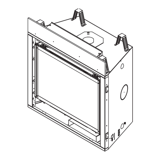
Page 39: Appliance Preparation
CNXT4842IFT models. Overheating will occur. See Section 5.A. Figure 6.5 (Generic Fireplace Shown) Remove the insulation from the outer vent pipe. Heatilator • CNXT4236IFT, CNXT4842IFT Installation Manual • 2515-980 Rev. R • 1/23... - Page 40 Figure 6.9 (Generic Fireplace Shown) Fold the center parts of the retaining band out and use to remove the seal cap. Heatilator • CNXT4236IFT, CNXT4842IFT Installation Manual • 2515-980 Rev. R • 1/23...
-
Page 41: Installing Optional Heat Management Systems
Figure 6.11 (Generic Fireplace Shown) Attach the first vent section (it will snap into place). Slide the insulation gasket onto the vent section, up against the appliance and over the tabs. Heatilator • CNXT4236IFT, CNXT4842IFT Installation Manual • 2515-980 Rev. R • 1/23... -
Page 42: Securing And Leveling The Appliance
This board must be used. See Figure 6.15. HEADER HEADER Figure 6.15 Non-combustible Board Note: Diagonal dimensions (A) and (B) must be within 1/4 inch of each other. Figure 6.13 Positioning the Appliance Squarely Heatilator • CNXT4236IFT, CNXT4842IFT Installation Manual • 2515-980 Rev. R • 1/23... -
Page 43: Venting And Chimneys
If predrilling holes, DO NOT penetrate inner pipe. INCORRECT Figure 7.4 Seams For 90º and 45º elbows that are changing the vent direction Heatilator • CNXT4236IFT, CNXT4842IFT Installation Manual • 2515-980 Rev. R • 1/23... -
Page 44: Assemble Vent Sections (Slp Pipe Only)
Use care when remov- ing termination cap from slip pipe. If slip section seals are broken during removal of the termination cap, vent could leak. Heatilator • CNXT4236IFT, CNXT4842IFT Installation Manual • 2515-980 Rev. R • 1/23... -
Page 45: Assemble Slip Sections (Dvp & Slp Pipe)
• Only outer pipes are sealed, sealing the inner flue is not required. • All unit collar, pipe, slip section, elbow and cap outer flues shall be sealed. Heatilator • CNXT4236IFT, CNXT4842IFT Installation Manual • 2515-980 Rev. R • 1/23... -
Page 46: Disassemble Vent Sections
Figure 7.11. • Pull carefully to separate the pieces of pipe. Figure 7.10 Rotate Seams for Disassembly Figure 7.11 Align and Disassemble Vent Sections Heatilator • CNXT4236IFT, CNXT4842IFT Installation Manual • 2515-980 Rev. R • 1/23... -
Page 47: Vertical Termination Requirements
Figure 7.12 Minimum Height From Roof to Lowest Discharge • Tighten nut and make sure the collar is tight against the Opening pipe section. • Caulk around the top of the storm collar. See Figure 7.15. Heatilator • CNXT4236IFT, CNXT4842IFT Installation Manual • 2515-980 Rev. R • 1/23... -
Page 48: Horizontal Termination Requirements
• Rest the small leg on the extended heat shield on top of the pipe section to properly space it from the pipe section. Figure 7.15 Figure 7.15 Important Notice: Heat shields may not be field constructed. Heatilator • CNXT4236IFT, CNXT4842IFT Installation Manual • 2515-980 Rev. R • 1/23... - Page 49 DVP-TRAP1 can adjust 1-1/2 in. (3-1/8 to 4-5/8 in.) DVP-TRAP2 can adjust 4 in. (5-3/8 to 9-3/8) DVP-HPC1 can adjust 2-1/8 in. (4-1/4 to 6-3/8) DVP-HPC2 can adjust 4-1/8 in. (6-3/8 to 10-1/2) Heatilator • CNXT4236IFT, CNXT4842IFT Installation Manual • 2515-980 Rev. R • 1/23...
-
Page 50: Electrical Information
Verify proper operation after servicing. WARNING! Risk of Shock! Replace damaged wire with type 105º C rated wire. Wire must have high temperature insulation. Heatilator • CNXT4236IFT, CNXT4842IFT Installation Manual • 2515-980 Rev. R • 1/23... - Page 51 IFT-ACM from the IFT-ECM. WIRE RETAINERS (4) IFT-ECM REAR PLACEMENT TAB IFT-ECM POWER SUPPLY IFT-ACM POWER CORD RF MODULE WIRE HARNESS IFT-ACM IFT-ECM FRONT PLACEMENT TAB Figure 8.2. Electrical Component Tray Heatilator • CNXT4236IFT, CNXT4842IFT Installation Manual • 2515-980 Rev. R • 1/23...
-
Page 52: Wiring Requirements
110-120 VAC IFT-RC150 WIRELESS GROUND WALL SWITCH (OPTIONAL) 3 PRONG 110VAC RF MODULE APPLIANCE 6V DC ON/OFF BATTERY PACK CONTROL (OPTIONAL) Figure 8.3 IntelliFire Touch Ignition System Wiring Heatilator • CNXT4236IFT, CNXT4842IFT Installation Manual • 2515-980 Rev. R • 1/23... - Page 53 Figure 8.4 Junction Box Wired to Wall Switch or BC10 (1/4 in. male) as shown. Heatilator • CNXT4236IFT, CNXT4842IFT Installation Manual • 2515-980 Rev. R • 1/23...
-
Page 54: Gas Information
4500 feet (1370 m). • If substituting for these components, please consult local codes for compliance. Check with your local gas utility to determine proper orifice size. Heatilator • CNXT4236IFT, CNXT4842IFT Installation Manual • 2515-980 Rev. R • 1/23... -
Page 55: Air Shutter Setting
NOTICE: If sooting occurs, provide more air by opening the air shutter. AIR SHUTTER WING NUT Figure 9.1 Air Shutter Air Shutter Settings Propane CNXT4236 5/8 in. Fully Open CNXT4842 5/8 in. 1/2 in. Heatilator • CNXT4236IFT, CNXT4842IFT Installation Manual • 2515-980 Rev. R • 1/23... -
Page 56: Finishing
HIGH TEMPERATURE (300 ºF/ 149 ºC MIN.) TOP AND SIDE SEAL JOINT BOTTOM 1 INCH (SHADED AREA) MAY BE COVERED WITH COMBUSTIBLE OR NON-COMBUSTIBLE MATERIAL Figure 10.1 Facing Materials Heatilator • CNXT4236IFT, CNXT4842IFT Installation Manual • 2515-980 Rev. R • 1/23... -
Page 57: Mantel And Wall Projections
= 35-1/2 IN. (CNXT4842IFT) Note: Measurement is taken from top of the opening, NOT the top of the fireplace. Figure 10.4 Minimum Vertical and Maximum Horizontal Dimensions - Non-Combustible Heatilator • CNXT4236IFT, CNXT4842IFT Installation Manual • 2515-980 Rev. R • 1/23... -
Page 58: Decorative Fronts
Craftsman Inside 0-6 Inches max. 10.8 Stop finishing material flush with opening. NON-COMBUSTIBLE FINISHING MATERIAL Figure 10.6 Finishing Material 1 Inch Thick or Less - Contour Decorative Front Heatilator • CNXT4236IFT, CNXT4842IFT Installation Manual • 2515-980 Rev. R • 1/23... - Page 59 DECORATIVE FRONT (Outside decorative front width) (Includes 1/8 in. opening each side of decorative front) Figure 10.7 Finishing Material Thickness Greater Than One Inch - Contour Decorative Front Heatilator • CNXT4236IFT, CNXT4842IFT Installation Manual • 2515-980 Rev. R • 1/23...
- Page 60 Finishing Material Thickness: 0-6 Inches Maximum (Inside Fit) NON-COMBUSTIBLE FINISHING MATERIAL DECORATIVE FRONT FINISHING MATERIAL FINISHING MATERIAL Figure 10.8 Simon/Craftsman Inside Fit Heatilator • CNXT4236IFT, CNXT4842IFT Installation Manual • 2515-980 Rev. R • 1/23...
-
Page 61: Appliance Setup
WARNING! Risk of Fire! Close the ball valve before in- stalling the splatter guard to prevent accidental lighting. Remove the splatter guard before lighting the appliance. Heatilator • CNXT4236IFT, CNXT4842IFT Installation Manual • 2515-980 Rev. R • 1/23... -
Page 62: Ember Placement
Lava rock ® Lava rock placement placement on placement on (shaded areas) sides and front sides and front of hearth pan. of hearth pan. Figure 11.3 Placement of Embers Heatilator • CNXT4236IFT, CNXT4842IFT Installation Manual • 2515-980 Rev. R • 1/23... -
Page 63: Install The Log Assembly
See Figure 3. Figure 1. Base Logs LOG PLACEMENT BRACKET LOG PLACEMENT BRACKET FOR LOG A (SRV2208-702) FOR LOG A (SRV2208-702) ALIGNMENT TABS ALIGNMENT TABS Figure 2. Figure 3. Heatilator • CNXT4236IFT, CNXT4842IFT Installation Manual • 2515-980 Rev. R • 1/23... - Page 64 FRONT FACE FRONT FACE Figure 4. Left Log and Right Log Reference Points Figure 5. Left Log in Proper Position Figure 6. Left and Right Log in Proper Position Heatilator • CNXT4236IFT, CNXT4842IFT Installation Manual • 2515-980 Rev. R • 1/23...
-
Page 65: Intellifire ® Touch Control System Setup
5. Wait to verify LED indicator on the ECM stops flash- ing. 6. Install batteries in the RC400 remote. 7. The RC400 remote will automatically pair to the appli- ance as pre-set at the factory. Heatilator • CNXT4236IFT, CNXT4842IFT Installation Manual • 2515-980 Rev. R • 1/23... -
Page 66: Reference Materials
(508 MM) 6 in. 14 IN. (152 mm) (356 MM) 12 IN. (305 MM) DVP-WS (Wall Shield Firestop) DVP-RDS ROOF DECK INSULATION SHIELD Figure 12.1 DVP Vent Components Heatilator • CNXT4236IFT, CNXT4842IFT Installation Manual • 2515-980 Rev. R • 1/23... - Page 67 79 mm 117 mm Length DVP-TRAP 5-3/8 in. 9-3/8 in. Trap2 Horizontal Termination Cap 137 mm 238 mm DVP-TRAP2 DVP-TRAP1 DVP-TRAPK2 DVP-TRAPK1 DVP-HPC1 DVP-HPC2 Figure 12.2 DVP Vent Components Heatilator • CNXT4236IFT, CNXT4842IFT Installation Manual • 2515-980 Rev. R • 1/23...
- Page 68 13-7/8 in. 9-1/2 in. (352 mm) (241 mm) 26 in. 660 mm 14 in. (356 mm) DVP-HSM-B DRC-RADIUS Extended Heat Shield Cap Shield Figure 12.3 DVP Vent Components Heatilator • CNXT4236IFT, CNXT4842IFT Installation Manual • 2515-980 Rev. R • 1/23...
- Page 69 DVP-TRAP to DVP-HPC Side Filler Kit 12-1/8 in. (181 mm) (314 mm) 8-3/4 in. (222 mm) 1-5/8 in. (41 mm) DVP-HPC High Performance Cap Figure 12.4 DVP Vent Components Heatilator • CNXT4236IFT, CNXT4842IFT Installation Manual • 2515-980 Rev. R • 1/23...
- Page 70 Only use listed decorative termination caps/shrouds with Hearth & Home Technologies approved venting systems. This applies to both DVP and SLP venting systems. Decorative Terminations Caps/Shrouds DTO134 DTO146 DTS134 DTS146 LDS33 LDS46 LDS-BV Figure 12.5 DVP Vent Components Heatilator • CNXT4236IFT, CNXT4842IFT Installation Manual • 2515-980 Rev. R • 1/23...
- Page 71 Option B: IFT-RC150, IFT-ACM, IFT-WFM and an IntelliFire App that can be downloaded from the app store. These accessories are purchased separately from the PVV-SLP. Contact your dealer to order. Figure 12.6 PVV-SLP Vent Components Heatilator • CNXT4236IFT, CNXT4842IFT Installation Manual • 2515-980 Rev. R • 1/23...
- Page 72 16-11/16 IN. (346 mm) 424 mm (424 mm) 12-1/2 IN. (318 mm) SLP-LPC SLP Low Profile Cap (Approved for use with PVI-SLP-B only) Figure 12.7 PVI-SLP-B Vent Components Heatilator • CNXT4236IFT, CNXT4842IFT Installation Manual • 2515-980 Rev. R • 1/23...
- Page 73 60 FT PV Wire Harness PVI-WH60 80 FT PV Wire Harness PVI-WH80 100 FT PV Wire Harness PVI-WH100 PVLP-HS PVLP-BEK Heat Shield Brick Kit Figure 12.8 PVLP-SLP Vent Components Heatilator • CNXT4236IFT, CNXT4842IFT Installation Manual • 2515-980 Rev. R • 1/23...
- Page 74 8-11/16 in. 1-1/2 in. 5-1/2 in. 12 in. 220 mm 38 mm 305 mm 146 mm SLP-WS SLP-FS Wall Shield Firestop Ceiling Firestop Figure 12.9 SLP Series Vent Components Heatilator • CNXT4236IFT, CNXT4842IFT Installation Manual • 2515-980 Rev. R • 1/23...
- Page 75 14-7/16 in. 59 mm 12-5/8 IN. 10-5/8 IN. 367 mm (321 mm) (270 mm) SLP-WT-BK SLP-RDS Wall Thimble-Black ROOF DECK INSULATION SHIELD Figure 12.10 SLP Series Vent Components Heatilator • CNXT4236IFT, CNXT4842IFT Installation Manual • 2515-980 Rev. R • 1/23...
- Page 76 10-11/16 in. 271mm 28-1/2 in. 4-1/8 in. 724 mm 105 mm 13-1/2 in. 4-3/4 in. 343 mm 121 mm SLK-SNKD Snorkel Termination Cap Figure 12.11 SLP Series Vent Components Heatilator • CNXT4236IFT, CNXT4842IFT Installation Manual • 2515-980 Rev. R • 1/23...
- Page 77 LDS33/LDS46 Decorative Shroud Catalog # LDS33 LDS46 1219 1829 Figure 12.12 SLP series Vent Components Heatilator • CNXT4236IFT, CNXT4842IFT Installation Manual • 2515-980 Rev. R • 1/23...
-
Page 78: Accessories
Please contact your Heatilator dealer with any questions or concerns. For the location of your nearest Heatilator dealer, please visit www.heatilator.com. Printed in U.S.A. - Copyright 2023 Heatilator • CNXT4236IFT, CNXT4842IFT Installation Manual • 2515-980 Rev. R • 1/23...