Table of Contents
Advertisement
Installation, Operation,
and Maintenance
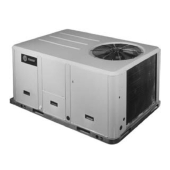
Packaged Rooftop Air Conditioners
Precedent™ — Gas/Electric
3 – 10 Tons – 60 Hz
Model Numbers
Only qualified personnel should install and service the equipment. The installation, starting up, and
servicing of heating, ventilating, and air-conditioning equipment can be hazardous and requires specific
knowledge and training. Improperly installed, adjusted or altered equipment by an unqualified person could
result in death or serious injury. When working on the equipment, observe all precautions in the literature
and on the tags, stickers, and labels that are attached to the equipment.
July 2012
YSC036E - YSC060E
YSC072F - YSC120F
YHC048F - YHC060F
SAFETY WARNING
YHC036E - YHC067E
YHC092E - YHC120E
YHC072F - YHC092F
RT-SVX21K-EN
Advertisement
Table of Contents
Troubleshooting

Related Manuals for Trane YHC092E


Summary of Contents for Trane YHC092E
- Page 1 3 – 10 Tons – 60 Hz YSC036E - YSC060E YHC036E - YHC067E Model Numbers YSC072F - YSC120F YHC092E - YHC120E YHC048F - YHC060F YHC072F - YHC092F SAFETY WARNING Only qualified personnel should install and service the equipment. The installation, starting up, and servicing of heating, ventilating, and air-conditioning equipment can be hazardous and requires specific knowledge and training.
- Page 2 Carbon (HCFCs). Not all refrigerants containing these Revision Summary compounds have the same potential impact to the RT-SVX21K-EN (18 July 2012) environment. Trane advocates the responsible handling of all refrigerants-including industry replacements for CFCs • MERV 8 filter with filter removal tool such as HCFCs and HFCs.
-
Page 3: Table Of Contents
Table of Contents Table of Contents Return Air Smoke Detector ......3 ... . .28 Main Electrical Power Requirements . - Page 4 Table of Contents Return Air Smoke Detector ReliaTel Refrigeration Module (RTRM) De- ... . . 48 fault Chart ......58 Economizer Start-Up .
-
Page 5: Model Number Description
Economizer, Dry Bulb 0-100% Convertible with Barometric Relief No Communications Interface Digit 4,5,6 - Nominal Gross Economizer, Reference Enthalpy Trane Communications Interface 0-100% without Barometric Relief LonTalk® Communications Interface Cooling Capacity (MBh) Economizer, Reference Enthalpy Novar 2024 Controls 3 Ton... -
Page 6: Model Number Notes
Model Number Description Switch without Barometric Relief for 21. Available for 3, 4, 5, 6, 7½, 8½ ton Clogged Filter Switch , Fan Failure horizontal configuration. standard/high efficiency models Switch and Condensate Drain Pan Barometric Relief for horizontal only. Overflow Switch configured units must be ordered Clogged Filter Switch , Discharge... -
Page 7: Unit Inspection
General Information Unit Inspection Compressor Nameplate As soon as the unit arrives at the job site The nameplate for the compressors are located on the side of the compressor. • Verify that the nameplate data matches the data on the sales order and bill of lading (including electrical data). -
Page 8: System Input Devices & Functions
FFS (Fan Failure Switch) If air flow through the unit is not is powered by 24 VAC. proven by the differential pressure switch connected to the RTCI - ReliaTel™ Trane Communication RTOM (factory set point 0.07 “w.c.) within 40 seconds Interface (Optional) -
Page 9: Low Pressure Control
General Information Compressor Disable (CPR1/2) Power Exhaust Control (Optional) This input incorporates the low pressure control (LPC) of ReliaTel Control each refrigeration circuit and can be activated by opening The power exhaust fan is started whenever the position of a field supplied contact installed on the LTB. the economizer dampers meets or exceed the power If this circuit is open before the compressor is started, the exhaust setpoint when the indoor fan is on. -
Page 10: Evaporator Frost Control
This electronic sensor features single setpoint capability and timed override with override cancellation. It is used ReliaTel™ Option with a Trane Integrated Comfort™ building management system. This input incorporates the Frostat™ control (FOS) mounted in the indoor coil circuit and can be activated by... -
Page 11: Smoke Detector Sensor (Optional)
General Information closing a field supplied contact installed in parallel with Maintenance Instructions provided with the literature the FOS. package for this unit. If this circuit is open before the compressor is started, the In order for the supply air smoke detector or return air compressor will not be allowed to operate. -
Page 12: Unit Dimensions
Unit Dimensions Figure 1, p. 12 illustrates the minimum operating and Providing less than the recommended clearances may service clearances for either a single or multiple unit result in condenser coil starvation, “short-circuiting” of installation. These clearances are the minimum distances exhaust and economizer airflows, or recirculation of hot necessary to assure adequate serviceability, cataloged condenser air. - Page 13 Unit Dimensions Figure 2. 3-5 ton standard efficiency, 3 ton high efficiency Notes: 1. All dimensions are in inches/millimeters. 2. ½ NPT Gas Connection Figure 3. 3-5 ton standard efficiency, 3 ton high efficiency - roof curb Note: All dimensions are in inches/millimeters. 44 MM 44 MM 1038...
- Page 14 Unit Dimensions Figure 4. 3-5 ton standard efficiency, 3 ton high efficiency - unit clearance and roof opening Note: All dimensions are in inches/millimeters. CLEARANCE 36” (914 MM) Figure 5. 6, 7½ (single) ton standard efficiency, 4-5 ton high efficiency Note: All dimensions are in inches/millimeters.
- Page 15 Unit Dimensions Figure 6. 6, 7½ (single) ton standard efficiency, 4-5 ton high efficiency - roof curb Note: All dimensions are in inches/millimeters. (356 MM) (2130 MM) Figure 7. 6, 7½ (single) ton standard efficiency, 4-5 ton high efficiency - unit clearance and roof opening Note: All dimensions are in inches/millimeters.
- Page 16 Unit Dimensions Figure 8. 7½ ton (dual) - 10 ton standard efficiency, 6 - 7½ (MCHE) ton high efficiency Note: All dimensions are in inches/millimeters. (TC MODELS) 2” ELECTRICAL CONNECTION (SINGLE POINT POWER WHEN HEAT INSTALLED) 1/2 NPT GAS CONNECTION (80 mbh, 120 mbh) 3/4 NPT GAS CONNECTION (150 mbh, 200 mbh, 250 mbh)
- Page 17 Unit Dimensions Figure 10. 7½ ton (dual) - 10 tons standard efficiency, 6 - 7½ (MCHE) ton high efficiency - unit clearance and roof opening Note: All dimensions are in inches/millimeters. Figure 11. 7½ (dehumidification) - 10 ton high efficiency Notes: 1.
- Page 18 Unit Dimensions Figure 12. 7½ (dehumidification) - 10 ton high efficiency - roof curb Notes: 1. All dimensions are in inches/millimeters. 18 1/2” (470 MM) 6 5/8” 83 7/8” (168 MM) 1” (2130 MM) (25 MM) 34 3/8” 56 3/8” (873 MM) (1432 MM) 18 1/2”...
-
Page 19: Installation
Installation Pre-Installation If an element has detached from its ceramic insulator, carefully put it back into place. Replace the heater elements if they present symptoms WARNING noted in item 2 or 3 above. Fiberglass Wool! Procedure Product contains fiberglass wool. Disturbing the insulation in this product during installation, maintenance or repair will expose you to airborne WARNING... - Page 20 YSC090F 7½ YSC092F 8½ YSC102F 1047 YSC120F 1156 1058 YHC037E YHC048E/YHC047E YHC048F YHC060E/YHC067E YHC060F YHC072F 7½ YHC092E 1552 1335 7½ YHC092F 1124 1026 204/ 8½ YHC102E 1579 1362 YHC120E 1589 1372 (a) Weights are approximate. (b) Corner weights are given for information only.
-
Page 21: Foundation
Installation (a),(b) Table 2. Factory installed options (fiops)/accessory net weights (lbs) (continued) Coil Guards Economizer Electric Heaters Hinged Doors Manual Outside Air Damper Motorized Outside Air Damper Novar Control Oversized Motor — — Powered Convenience Outlet Powered Exhaust Reheat Coil —... - Page 22 Installation Figure 17. 4-6 ton high efficiency units, 7½ Figure 19. 3-5 ton standard efficiency units & 3 ton high (Microchannel) high efficiency unit and 6-10 efficiency units - Down flow supply & return air ton standard efficiency units - horizontal openings w/ through the base utilities supply &...
-
Page 23: Roof Curb
Installation Roof Curb Figure 22. View for base to roof curb alignment YHC092-120E (except YHC092F) on 50" x Downflow 84" roof curb The roof curbs for these units consists of a “full perimeter” enclosure to support the unit just inside of the unit base rail. -
Page 24: General Unit Requirements
Installation A Rigging illustration and Center-of-Gravity dimensional Figure 25. Fork pockets - 7½ (Dehumidification) - 10 ton data table is shown in Figure 15, p. 20. Refer to the typical high efficiency units unit operating weights table before proceeding. 3. Remove all drill screws fastening wood protection to metal base rail. -
Page 25: Temperature Limit Switch Usage For Gas Heat Units
Some, but not all units require a YSC092E**(H,Z), YSC102F**(H,Z), different TCO1 limit switch, which is attached to the YSC120F**(M,Y), YSC120F**(H,Z), combustion blower motor if horizontal discharge YHC092E**(M,Y),YHC092F**(M,Y), configuration is used. YHC102E**(M,Y), YHC120E**(L,X), YHC120E**(H,Z). Note: The following units require a limit switch change out for horizontal discharge. -
Page 26: Horizontal Discharge Conversion (3 Through 5 Ton Units)
Installation Table 3. TC01 tripping values (continued) TCO1 Tripping TCO1 Tripping Unit Model Values Unit Model Values (Standard Down flow/ (High Efficiency - 15 Down flow/ Efficiency) Horizontal SEER) Horizontal YSC102F**(L,X) 225F YHC092F**(M,Y) 180F / 200F YSC102F**(M,Y) 230F YHC092F**(H,Z) 200F YSC102F**(H,Z) 200F / 260F YHC102E**(L,X) -
Page 27: Horizontal Discharge Conversion (6 Through 10 Ton Units)
Installation Figure 29. Duct cover WARNING Hazardous Voltage! Disconnect all electric power, including remote disconnects before servicing. Follow proper lockout/ tagout procedures to ensure the power can not be RTV Sealant inadvertently energized. Failure to disconnect power before servicing could result in death or serious injury. 1. -
Page 28: Tco1 Instructions
Figure 34. Horizontal view 1 the TCO1 shipped attached to the combustion blower for horizontal operation. 4. Replace heat section access panel. Figure 32. TCO1 location (YHC092E-120E) TCO1 limit is located above the burner on the YHC092E, YHC102E, YHC120E models... -
Page 29: Main Electrical Power Requirements
Figure 34, 28. For YHC047E-067E, YHC048E/F-060E/F ,YSC072F- • Inspect all control panel components; tighten any 120F , YHC092E-120E and YHC072F-092F units secure loose connections. the tab on left side to the indoor coil block off with one • Connect properly sized and protected power supply... -
Page 30: Requirements For Gas Heat
Installation Condensate Drain Configuration 4. Disconnect the 5" pipe nipple and union from the “Through the Base Gas” kit assembly. An evaporator condensate drain connection is provided 5. Using pipe sealant, attach the 6½” nipple and gas on each unit. Refer to Figure 16, p. -
Page 31: Filter Installation
Installation Field Installed Power Wiring A condensate trap must be installed at the unit due to the drain connection being on the “negative pressure” side of the fan. Install the P-Trap using the guidelines in Figure 37, WARNING A condensate drain line must be connected to the P-Trap. Proper Field Wiring and Grounding Pitch the drain lines at least 1/2 inch for every 10 feet of Required! -
Page 32: Standard Wiring
Installation Figure 38. All units except 7½ (dehumidification)-10 ton WARNING high efficiency units Hazardous Voltage! Disconnect all electric power, including remote disconnects before servicing. Follow proper lockout/ tagout procedures to ensure the power can not be inadvertently energized. Failure to disconnect power before servicing could result in death or serious injury. -
Page 33: Control Power Transformer
Installation Control Power Transformer Table 5. Electromechanical thermostat 24V AC conductors with electromechanical unit The 24 volt control power transformers are to be used only with the accessories called out in this manual. Distance from Unit Recommended to Control Wire Size Transformers rated greater than 50 VA are equipped with internal circuit breakers. - Page 34 Installation Figure 40. Typical field wiring diagrams for Figure 43. ReliaTel relative humidity sensor electromechanical (dehumidification option) Figure 44. ReliaTel humidistat (dehumidification option) Figure 41. ReliaTel conventional thermostat field wiring diagrams RTRM Figure 42. ReliaTel options module RT-SVX21K-EN...
- Page 35 Installation Figure 45. Electromechanical control customer low voltage routing (all units except 7½ (dehumidification) - 10 ton high efficiency) Figure 46. ReliaTel control customer low voltage routing (all units except 7½ (dehumidification) - 10 ton high efficiency) RT-SVX21K-EN...
- Page 36 Installation Figure 47. ReliaTel (without TBUE) control customer wire routing (7½ (dehumidification) - 10 ton high efficiency) Figure 48. ReliaTel (with TBUE) control customer wire routing (7½ (dehumidification) - 10 ton high efficiency) RT-SVX21K-EN...
- Page 37 Installation Figure 49. Electromechanical (without TBUE) control customer wire routing (7½ (dehumidification) - 10 ton high efficiency) Figure 50. Electromechanical (with TBUE) control customer wire routing (7½ (dehumidification) - 10 ton high efficiency) RT-SVX21K-EN...
-
Page 38: Smoke Detector Customer Low Voltage Wiring
Installation Smoke Detector Customer Low Figure 52. Up to 10 HVAC units If you have more than 5 HVAC units, you can connect all Voltage Wiring the supplies together on one power supply (up to 10 HVAC units), and all the returns together (up to 10 HVAC When interlocking System Sensor smoke detectors units) on another power supply. - Page 39 Installation Figure 53. Examples RT-SVX21K-EN...
- Page 40 Installation Figure 54. Typical field wiring diagrams for optional controls (ReliaTel only) BAYSENS075* BAYSENS075* BAYSENS108* BAYSENS106* BAYSENS110* BAYSENS119* BAYSENS073* BAYSENS074* BAYSENS075* ASYSTAT669A OPTIONAL REMOTE SENSOR RT-SVX21K-EN...
- Page 41 Installation Table 7. Temperature vs. resistance Table 9. Iron pipe size (SI) millimeters Temperature Iron Pipe Size (SI) Millimeters Degrees F° Degrees C° Nominal Resistance Length of Pipe 15 mm 20 mm 25 mm 32 mm 40 mm -20° -28.9° 170.1 K - Ohms (Meters) Pipe...
-
Page 42: Pre-Start
Pre-Start Use the checklist provided below in conjunction with the within the proper tolerances, notify the power company to “General Unit Requirements” checklist to ensure that the correct this situation before operating the unit. unit is properly installed and ready for operation. Excessive three phase voltage imbalance between phases will cause motors to overheat and eventually fail. -
Page 43: Compressor Crankcase Heaters (Optional)
Pre-Start • Close the field supplied main power disconnect switch Close the main power disconnect switch and the unit or circuit protector switch that provides the supply mounted disconnect switch, if applicable. power to the unit. Note: Upon closing main power disconnect and the unit Note: Upon closing main power disconnect and the unit mounted disconnect switch or circuit breaker, the mounted disconnect switch or circuit breaker, the... -
Page 44: Test Modes
Pre-Start Table 10. Service test guide for component operation Test Multi-Speed Fan Step Mode Econ Comp 1 Comp 2 Heat 1 Heat 2 Resistance Output Output Minimum Position Setpoint 0% Ω 2.2K Minimum Selectable Ventilation Economizer Ω Open 3.3K Test Open Cool Minimum Ω... - Page 45 Pre-Start Cool 1 Connect red thermostat wire (R) to yellow thermostat wire (Y1). Cool 2 Connect red thermostat wire (R) to yellow thermostat wire (Y2). Heat 1 Connect red thermostat wire (R) to brown thermostat wire (W1). Heat 2 Connect red thermostat wire (R) to brown thermostat wire (W2).
-
Page 46: Unit Start-Up
Unit Start-Up Verifying Proper Air Flow 1. Measure the supply and return duct static pressure and sum the resulting absolute values, 2. Use the accessory pressure drop table in the Service WARNING Facts, to calculate the total static pressure drop for all of the accessories installed on the unit;... -
Page 47: Units With Direct Drive Indoor Fan - Electromechanical Control
Unit Start-Up direction of rotation is indicated by an arrow on the fan Using the Service Test Guide in Table 10, p. 60, housing. momentarily jump across the Test 1 & Test 2 terminals on LTB1. Repeat process until Service Test Mode is at Cool 2 With the fan operating properly, determine the total (2-Steps of Cooling Applications Only) or Cool 3 (3-Steps system airflow (CFM) by (ReliaTel/Electromechanical):... -
Page 48: Units With Constant Cfm Direct Drive Indoor
Unit Start-Up 1. Measure the DC voltage across pins Vt and com on the provides a constant CFM base on voltage output for the MMC board or note the DC voltage shown on the ECM potentiometer on the RTOM board. Before starting the board display. -
Page 49: Economizer Start-Up
Unit Start-Up below. Failure to follow these instructions will prevent the smoke detector from performing its design function. WARNING Live Electrical Components! Economizer Start-Up During installation, testing, servicing and troubleshooting of this product, it may be necessary to WARNING work with live electrical components. Have a qualified licensed electrician or other individual who has been Live Electrical Components! properly trained in handling live electrical components... -
Page 50: Compressor Start-Up
Unit Start-Up 4. To stop the SERVICE TEST, turn the main power the supply temperature rises 10°F more than when in disconnect switch to the “Off” position or proceed to cooling mode stage 2. the next component start-up procedure. Remove Monitor the suction pressure for 15 minutes. -
Page 51: Maintenance
Maintenance Fan Belt Adjustment - Belt Drive Note: Actual belt deflection “force” must not exceed the maximum “force” value shown in Figure 56, p. Units 7. Recheck the belt tension at least twice during the first 2 to 3 days of operation. Belt tension may decrease until the new belts are “run in”... -
Page 52: Condensate Overflow Switch
Maintenance Return Air Smoke Detector Maintenance • Record this data on an “operator’s maintenance log” like the one shown in Table 14, p. 54. If the operating Airflow through the unit is affected by the amount of dirt pressures indicate a refrigerant shortage, measure the and debris accumulated on the indoor coil and filters. - Page 53 Maintenance Microchannel (MCHE) Coils 2. Protect all electrical devices such as motors and controllers from any over spray. 3. Straighten any bent coil fins with a fin comb. NOTICE: Coil Damage! WARNING DO NOT use any detergents with microchannel Hazardous Pressures! condenser coils.
-
Page 54: Annual Maintenance
Maintenance 11. Restore the unit to its operational status and check system operation. Annual Maintenance • Clean and repaint any corroded surface. Final Process For future reference, you may find it helpful to record the unit data requested in the blanks provided. Complete Model Number: Unit Serial Number: Wiring Diagram Numbers... -
Page 55: Troubleshooting
Troubleshooting ReliaTel™ Control modes. If a problem in operation is noted in any mode, you may leave the system in that mode for up to one hour while troubleshooting. Refer to the sequence of The RTRM has the ability to provide the service personnel operations for each mode, to assist in verifying proper with some unit diagnostics and system status information. -
Page 56: Method 2
Troubleshooting System Failure the previous section for the recommended troubleshooting procedure. • Measure the voltage between terminals J6-9 & J6-6. Heating Failure • Normal Operation = approximately 32 VDC Verify Heat Failure by Ignition Module (IGN) LED indicator: • System Failure = less than 1 VDC, approximately 0.75 OFF: No Power or Failure •... -
Page 57: Method 2
Troubleshooting After approximately 30 seconds, turn the “Mode” Sensor Module electrically removed from the selection switch to the desired mode, i.e. Heat, Cool or system. Auto. Test 1 - Zone Temperature Thermistor Method 2 (ZTEMP) To reset the system at the unit, cycle the unit power by This component is tested by measuring the resistance turning the disconnect switch “Off”... -
Page 58: Relative Humidity Sensor Test
Troubleshooting ReliaTel Refrigeration Module (RTRM) leads for the opposite direction. The LED should have at least 100 times more resistance in reverse direction, as Default Chart compared with the forward direction. If high resistance in If the RTCI loses input from the building management both directions, LED is open. -
Page 59: Electromechanical Control
Troubleshooting Heating Failure 5 Flashes: OA Quality Sensor 6 Flashes: OA Humidity Sensor Verify Heat Failure by Ignition Module (IGN) LED indicator: 7 Flashes: OA Temp Sensor • OFF: No Power or Failure 8 Flashes: MA Temp Sensor • ON: Normal 9 Flashes: RAM Fault •... -
Page 60: Test 1
Troubleshooting Test 1 The resistance should be approximately 390 Ohms. Replace the Switch if it is open. Verifying that the economizer actuator (ECA) is functional: Replace the ECA if it is out of range. 1. Using the “Test Mode” described in the “System Start- Up”... -
Page 61: Unit Wiring Diagrams Numbers
Unit Wiring Diagrams Numbers Note: Wiring diagrams can be accessed using e-Library by entering the diagram number in the literature order number search field or by contacting technical support. Table 17. Unit wiring diagram numbers Schematic Type Drawing Number Description 4366-7217 YHC(037-067) 4366-4571... - Page 62 Unit Wiring Diagrams Numbers Table 17. Unit wiring diagram numbers (continued) Schematic Type Drawing Number Description 4366-7340 YHC(037) (230V) 4366-7342 YHC(047-067) (230V) 4366-4564 Y(S,H)C(036,048)E/F (1-Phase), ReliaTel Controls YHC(036,048)E/F (230V 3-Phase), ReliaTel Controls, 4366-5185 X13 IDM Y(S,H)C(036-060)E/F (230V 3-Phase), ReliaTel 4366-1522 Controls, Belt-Drive IDM 230V Connection...
-
Page 63: Limited Warranty
If you wish further help or information This limited warranty is extended by Trane to the original concerning this limited warranty, contact: purchaser and to any succeeding owner of the real... - Page 64 The manufacturer has a policy of continuous product and product data improvement and reserves the right to change design and specifications without notice. © 2012 Trane All rights reserved We are committed to using environmentally RT-SVX21K-EN 18 Jul 2012 conscious print practices that reduce waste.