Table of Contents
Advertisement
Quick Links
SPECIFICATION
CONTROL
DRAWING
NOTES:
1. DESCRIPTION: G1000 Installation Documentation -
2. PAGE SIZE:
3. PAGINATION:
48
4. MATERIAL: 24 pound bond. Approved equivalents allowed.
5. COLOR: Black Ink on White Paper Stock.
6. BINDERY: Three-hole punch, shrink-wrap. Digital output preferred
7. FOLDS: Z-Fold tabloid sheets at end of document.
8. ELECTRONIC ARTWORK: Shall Conform to Garmin Archive, Filename:
The following files have been archived under the above ARCHIVE FILENAME.
Filename
190-00303-05.pdf
release.indd
Manual Elements
*.*
CONFIDENTIAL
This drawing and the specifications contained herein are the property of Garmin
Ltd. or its subsidiaries and may not be reproduced or used in whole or in part as
the basis for manufacture or sale of products without written permission .
John Sherman
Drafter:
Daniel Cobb
Checker:
Project Engineer:
Craig Parker
Released By:
SDT
REV.
DATE
Q
12/29/09
Added antenna note
R
03/23/10
Added Standalone Rack info
S
07/29/10
Added updated NAV/COM unit
3-Hole
Punch
DER REVIEW REQUIRED
Letter: Width = 8.5 inches, Height = 11 inches
Tabloid: Width = 11.0 inches, Height = 17.0 inches
double-sided letter sheets.
File Contents
Portable Document Format, contains Installation Manual and Release Specification
Adobe InDesign Format, Release Specification
Word 97 for PC, Formatted Files and Figures
Various supporting illustrations, drawings, and artwork.
Date:
TITLE:
11/17/03
11/17/03
SIZE
A
11/17/03
Scale:
11/18/03
REVISIONS
DESCRIPTION
8.5"
GIA 63/GIA 63W
Installation Manual
11"
GIA 63/GIA 63W Installation Manual
single-sided tabloid sheets.
11
GIA 63/GIA 63W Installation Manual
PART NO:
190-00303-05
N/A
DER REVIEW REQUIRED
ECO NO.
68178
70476
73976
190-00303-05.pdf
Garmin Ltd. or its subsidiaries
c/o Garmin International, Inc.
1200 E. 151st Street
Olathe, Kansas 66062 U.S.A.
1
Sheets
REV.
S
1
of
Advertisement
Table of Contents

Related Manuals for Garmin GIA 63W


Summary of Contents for Garmin GIA 63W
- Page 1 Various supporting illustrations, drawings, and artwork. Garmin Ltd. or its subsidiaries CONFIDENTIAL This drawing and the specifications contained herein are the property of Garmin c/o Garmin International, Inc. Ltd. or its subsidiaries and may not be reproduced or used in whole or in part as 1200 E.
- Page 2 GIA 63/GIA 63W Installation Manual 190-00303-05 July, 2010 Revision S...
- Page 3 Except as expressly provided herein, no part of this manual may be reproduced, copied, transmitted, disseminated, downloaded or stored in any storage medium, for any purpose without the express prior written consent of Garmin. Garmin hereby grants permission to download a single copy of this manual and of any revision to this manual onto a hard drive or other electronic...
- Page 4 Section 2 2-1 – 2-16 Section 3 3-1 – 3-6 Section 4 4-1 – 4-30 Appendix A A-1 – A-4 Appendix B B-1 – B-8 Appendix C C-1 – C-14 GIA 63/GIA 63W Installation Manual Page i 190-00303-05 Revision S...
- Page 5 This manual reflects the operation of main software version 5.31 for the GIA 63 and main software version 6.00 for the GIA 63W. Some differences in operation may be observed when comparing the information in this manual to earlier or later software versions.
-
Page 6: Table Of Contents
2.3 Rack Considerations ..........................2-9 2.4 Cabling and Wiring..........................2-10 2.5 Cooling Air ............................2-10 2.6 GIA 63 Minimum Installation Requirements ..................2-11 2.7 GIA 63W Minimum Installation Requirements ................2-12 2.8 Mounting Requirements ........................2-13 INSTALLATION PROCEDURE......................3-1 3.1 Unpacking Unit..........................3-1 3.2 Wiring Harness Installation .......................3-1 3.3 Antenna Installation...........................3-2... - Page 7 C-1 GIA 63(W) Example Interconnect (Sheet 7 of 7)................C-13 LIST OF TABLES TABLE PAGE 3-1 Pin Contact Part Numbers........................3-1 3-2 Recommended Crimp Tools ......................3-1 3-3 Long Term Power Interrupt Category A (200 mS) Mod Status ............3-4 Page iv GIA 63/GIA 63W Installation Manual Revision S 190-00303-05...
- Page 8 The table is current at the time of publication of this manual (see date on front cover) and is subject to change without notice. Authorized Garmin Sales and Service Centers are encouraged to access the most up-to-date bulletin and advisory information on the Garmin Dealer Resource web site at www.garmin.com using their Garmin-provided user name and password.
- Page 9 GIA 63W HARDWARE MOD LEVEL HISTORY The following table identifies hardware modification (Mod) Levels for the GIA 63W. Mod Levels are listed with the associated service bulletin number, service bulletin date, and the purpose of the modification. The table is current at the time of publication of this manual (see date on front cover) and is subject to change without notice.
-
Page 10: General Description
This manual presents mechanical and electrical installation requirements for installing the GIA 63(W) as part of a Garmin Integrated Flight Deck. The GIA 63(W) can be integrated into a variety of airframes under an appropriate TC or STC. Each airframe installation may vary. Use only approved (type or supplemental type) data for specific installation instructions in a particular aircraft. -
Page 11: Interface Summary
• Autopilot • Altitude encoder/serializer • Fuel management systems • Lightning detection systems • Traffic awareness systems • Data link systems • External annunciators • DME (including King Serial) • Page 1-2 GIA 63/GIA 63W Installation Manual Revision S 190-00303-05... -
Page 12: Technical Specifications
GIA 63 Environmental Qualification Form, Garmin part number 005-00148-02 GIA 63W Environmental Qualification Form, Garmin part number 005-00235-00 To obtain a copy of this form, see the dealer/OEM portion of the Garmin web site (www.garmin.com). 1.4.2 Physical Characteristics Characteristics... - Page 13 1.4.5 WAAS Specific GPS Specifications (GIA 63W only) Characteristics Specifications Number of channels 15 (12 GPS and 3 GPS/WAAS/SBAS) Frequency 1575.42 MHz L1, C/A code Sensitivity (acquisition) -116 dBm to -134.5 dBm GPS -116 dBm to -134.5 dBm WAAS Sensitivity (drop lock)
- Page 14 500 Ω load when the transmitter is Sidetone 1.4 V modulated at least 70%. Demodulated Audio Response Shall be less than 6 dB when the audio input frequency is varied from 350 to 2500 Hz. GIA 63/GIA 63W Installation Manual Page 1-5 190-00303-05 Revision S...
- Page 15 20 dB. Audio Distortion The distortion in the receiver audio output shall not exceed 10% at all levels up to 100 mW. Selectivity 6 dB BW is greater than 16.5 kHz. Page 1-6 GIA 63/GIA 63W Installation Manual Revision S 190-00303-05...
- Page 16 1020 Hz shall be attenuated at least 20 dB. Audio Distortion The distortion in the receiver audio output shall not exceed 10% at all levels up to 100 mW. GIA 63/GIA 63W Installation Manual Page 1-7 190-00303-05 Revision S...
- Page 17 (see Sections 4.7.2.1 and 4.10.7) (Main 2 Connector) Power Requirements for P605 1.0 A max @ 27.5 Vdc (Without Superflags Active) (Main 2 Connector) 2.0 A max @ 13.75 Vdc (Without Superflags Active) Page 1-8 GIA 63/GIA 63W Installation Manual Revision S 190-00303-05...
- Page 18 GIA 63W 011-01105-01 A (200mS) 011-01105-20 A (200mS) * Refer to Mod Status Table in front of manual for applicable mod levels. ** Refer to the Section 3.8 for Continued Airworthiness. GIA 63/GIA 63W Installation Manual Page 1-9 190-00303-05 Revision S...
-
Page 19: License Requirements
The article may be installed only if performed under 14 CFR part 43 or the applicable airworthiness requirements. At the time of publication, installations of this TSO approved article are only approved when installed in an aircraft as part of a Garmin Integrated Flight Deck. - Page 20 006-C0044-() TSO-C129a 006-B0093-00 except Class A1 ETSO-C129a 006-B0190-00 006-B0093-01 006-C0047-() through 006-B0190-04 006-C0046-() TSO-C151b Class A and B 006-B0190-() 006-C0044-() except TAWS 006-B0190-00 006-C0047-() ETSO-C151a Class B through 006-C0039-01 006-B0190-29 GIA 63/GIA 63W Installation Manual Page 1-11 190-00303-05 Revision S...
- Page 21 3. Garmin was granted a deviation from TSO-C9c subpart A (c), which requires marking the weight of the unit on the unit. Garmin will provide this information in the installation manual in lieu of marking on the serial tag. Garmin does not currently list the weight on other avionics units.
- Page 22 For abnormal operating conditions power input tests, satellite acquisition time of 5 minutes applies. TSO-C151b 1. Garmin was granted a deviation from TSO-C151b 4.a. to mark the unit with the serial number instead of the date of manufacture. GIA 63/GIA 63W Installation Manual...
- Page 23 1.6.3 GIA 63W TSO/ETSO Compliance Applicable LRU SW Part Applicable CLD Part Function TSO/ETSO Category Numbers Numbers 006-C0084-0() except 006-B0544-1() 006-C0084-00 through 006-C0072-0() 006-B0544-3() TSO-C9c and all 006-C0085-0() Automatic Pilots ETSO-C9c 006-B0544-B() except 006-C0039-0() 006-B0544-BA except through 006-C0039-00 006-B0544-BB through...
- Page 24 GIA 63W TSO/ETSO Compliance, Continued Applicable LRU SW Part Applicable CLD Part Function TSO/ETSO Category Numbers Numbers 006-C0084-0() except 006-C0084-00 006-C0072-0() 006-B0544-1() through 006-C0085-0() 006-B0544-3() 006-B0082-0() TSO-C40c and all except 006-C0039-0() VOR Receiver ETSO-2C40c 006-B0544-B() 006-B0082-00 except except through 006-C0039-00...
- Page 25 GIA 63W TSO/ETSO Compliance, Continued Applicable LRU SW Part Applicable CLD Part Function TSO/ETSO Category Numbers Numbers 006-C0084-0() TSO-C151b Class A except and B 006-B0544-1() 006-C0084-00 through 006-C0072-0() 006-B0544-3() 006-C0085-0() and all TAWS 006-B0544-B() except 006-C0039-0() 006-B0544-BA ETSO-C151a Class B...
- Page 26 3. Garmin was granted a deviation from TSO-C9c subpart A (c), which requires marking the weight of the unit on the unit. Garmin will provide this information in the installation manual in lieu of marking on the serial tag. Garmin does not currently list the weight on other avionics units.
- Page 27 160D. TSO-C52b 1. Garmin was granted a deviation from SAE AS 8008 paragraph 3.6 to limit flight director operation to attitudes considered safe for the certified aircraft. 2. Garmin was granted a deviation from TSO-C52b to use DO-160E instead of DO-160C.
- Page 28 TSO-C151b 1. Garmin was granted a deviation from TSO-C151b to use DO-160E instead of DO-160D. 2. Garmin was granted a deviation from TSO-C151b 4.a. to mark the unit with the serial number instead of the date of manufacture. GIA 63/GIA 63W Installation Manual...
- Page 29 TSO/ETSO Deviations, continued TSO/ETSO Deviation ETSO-C151a 1. Garmin was granted a deviation from ETSO-C151a to use DO-160E instead of DO- 160D. TSO-C169 1. Garmin was granted a deviation from TSO-C169 to use DO-160E instead of DO-160D. 2. Garmin was granted a deviation to TSO-C169, paragraph 4.d requirement to mark the installation procedures drawing number on the equipment.
- Page 30 1.6.5 GIA 63W Updated NAV/COM TSO/ETSO Compliance Applicable LRU SW Part Applicable CLD Part Function TSO/ETSO Category Numbers Numbers 006-C0084-0() 006-B0544-3() except except 006-C0084-00 006-B0544-30 006-C0072-0() through 006-B0544-34 Automatic Pilots TSO-C9c and all 006-B0544-B() except 006-C0085-0() 006-B0544-BA through 006-B0544-BD 006-C0084-0()
- Page 31 GIA 63W Updated NAV/COM TSO/ETSO Compliance, Continued Applicable LRU SW Part Applicable CLD Part Function TSO/ETSO Category Numbers Numbers 006-B0544-3() 006-C0084-0() except except 006-B0544-30 006-C0084-00 through 006-C0072-0() 006-B0082-1() 006-B0544-34 VOR Receiver TSO-C40c 006-C0085-0() except and all 006-B0082-10 006-B0544-B() except 006-C0124-0()
- Page 32 GIA 63W Updated NAV/COM TSO/ETSO Compliance, Continued Applicable LRU SW Part Applicable CLD Part Function TSO/ETSO Category Numbers Numbers 006-C0084-0() 006-B0544-3() except except 006-C0084-00 006-B0544-30 006-C0072-0() through TSO-C151b Class A 006-B0544-34 TAWS and B and all 006-B0544-B() except 006-C0085-0() 006-B0544-BA...
- Page 33 3. Garmin was granted a deviation from TSO-C9c subpart A (c), which requires marking the weight of the unit on the unit. Garmin will provide this information in the installation manual in lieu of marking on the serial tag. Garmin does not currently list the weight on other avionics units.
- Page 34 FAA, authorization to conduct any GPS or WAAS operation under Instrument Flight Rules (IFR) requires that: 1. Aircraft using the GPS or WAAS capability of the GIA 63W navigation equipment under IFR must be equipped with an approved and operational alternate means of navigation appropriate to the flight with the exception of oceanic and remote operations.
- Page 35 GARMIN GNSS (GPS/SBAS) NAVIGATION SYSTEM EQUIPMENT APPROVALS The Garmin GNSS navigation system installed in this aircraft is a GPS system with a Satellite Based Augmentation System (SBAS) comprised of [two TSO-C145a Class 3 approved Garmin GIA 63Ws, TSO-C146a Class 3 approved Garmin GDU 1XXX Display Units, Garmin GA36 and GA37 antennas, and GPS software version 3.2 or later approved version].
- Page 36 BRNAV operations in accordance with AC 90-96A and JAA TGL-10 Rev 1. This does not constitute an operational approval. Garmin International holds an FAA Type 2 Letter of Acceptance (LOA) in accordance with AC 20-153 for database integrity, quality, and database management practices for the Navigation database. Pilots and operators can view the LOA status at www.garmin.com...
- Page 37 The navigation equipment required to join and fly an instrument approach procedure is indicated by the title of the procedure and notes on the IAP chart. Use of the Garmin GPS/SBAS receivers to provide navigation guidance during the final approach segment of an ILS, LOC, LOC-BC, LDA, SDF, MLS or any other type of approach not approved for “or GPS”...
- Page 38 (Glideslope Receiver) EUROCAE ED-72A (GPS) SAE AS 402B (Automatic Pilots) SAE AS 8008 (Flight Director Equipment) 1.6.9 Other Regulatory Criteria (GIA 63W) RTCA/DO-254 Level A and C** (CLD devices) RTCA/DO-254 Level A*** (CLD devices) RTCA/DO-178B Level A*, B, C, D (Software)
-
Page 39: Referenced Documents
GA 56W Antenna Installation Instructions Antenna Minimum Performance Specification 004-00287-00 for Garmin’s GPS/WAAS Receiver System * GA 55 technical specifications and antenna performance is contained in the GDL 69/69A Installation Manual. Page 1-30 GIA 63/GIA 63W Installation Manual Revision S 190-00303-05... -
Page 40: Limited Warranty
(iv) damage caused by service performed by anyone who is not an authorized service provider of Garmin; or (v) damage to a product that has been modified or altered without the written permission of Garmin. - Page 41 This page intentionally left blank Page 1-32 GIA 63/GIA 63W Installation Manual Revision S 190-00303-05...
-
Page 42: Installation Overview
AC 43.13-1B and AC 43.13-2B, where applicable, may be found useful for making retro-fit installations that comply with FAA regulations. Refer to the G1000 System Installation Manual, Garmin part number 190-00303-00 for further details on the mechanical aspects. For installation in an aircraft using the remote mounted standalone rack, refer to Appendix B for rack drawings and dimensions. - Page 43 In addition, TSO-C144 antennas can also meet TSO-C129a requirements for the GIA 63 (non-WAAS) if their additional gain (which is about 16dB at 1.5 GHz for antennas produced by Garmin) is offset by added attenuation in-line with the GIA 63 (non-WAAS). If an in-line attenuator is used, it must pass DC current (40 mA max at 4.6 VDC) which is provided from the GPS receiver to the antenna pre-amplifier.
- Page 44 2.1.3.2 Required WAAS Antennas for the GIA 63W The following is a list of TSO-C144 antennas that allow the GIA 63W with GPS software version 3.00 or later to meet TSO-C145a requirements without requiring the operational limitations specified in Section 1.6.5 of this manual:...
- Page 45 The following is a list of known TSO-C144 antennas that allow the GIA 63W with any version of GPS software version to meet TSO-C145a requirements with the operational limitations specified in Section 1.6.5 of this manual: SATCOM Antenna Garmin Mount...
-
Page 46: Installation Considerations
4. Obtain FAA Advisory Circular AC-183C and identify a DER from the roster of individuals in it. 5. Contact an aviation industry organization such as the Aircraft Electronics Association for assistance. GIA 63/GIA 63W Installation Manual Page 2-5 190-00303-05 Revision S... - Page 47 (re-radiating) ELT transmitter. Note: The separation requirement does not apply to GPS and COM combination antennas, provided the antenna model is TSO authorized and has been tested to meet Garmin’s minimum performance standards. The separating requirement includes the combination with an XM antenna element as well.
- Page 48 Figure 2-1 shows the recommended placement of antennas. Figure 2-1. GPS Antenna Considerations GIA 63/GIA 63W Installation Manual Page 2-7 190-00303-05 Revision S...
- Page 49 No special precautions need to be taken to provide a bonding path between the GPS antenna and the aircraft structure. Follow the manufacturers’ instructions for the COM, VOR/LOC and Glideslope antennas. Page 2-8 GIA 63/GIA 63W Installation Manual Revision S 190-00303-05...
-
Page 50: Rack Considerations
Locate the GIA 63(W) as far as possible from all COM antennas. If a COM antenna is found to be the problem, a 1.57542 GHz notch filter (Garmin P/N 330-00067-00) may be installed in the VHF COM coax, as close to the COM as possible. This filter is not required for the GIA 63(W) transmitter. -
Page 51: Cabling And Wiring
2.4 Cabling and Wiring Extended barrel contacts for AWG #16, #18 and #20 wire are available from Garmin, if required. Special thin-wall heat shrink tubing is also provided to insulate the extended barrels inside the backshell. If using AWG #16 or #18 barrel contacts, ensure that no two contacts are mounted directly adjacent to each other. -
Page 52: Gia 63 Minimum Installation Requirements
2.6 GIA 63 Minimum Installation Requirements Below is a list of required devices for TSO-C129a category A1 certification. Pressure Altitude Device This device delivers pressure altitude data to the GIA 63. This data comes from the Garmin GDC 74A Air Data Computer. Manual Course Device This device delivers the manual course select to the GIA 63, which is required for the VOR receiver, and optional for the GPS receiver. -
Page 53: Gia 63W Minimum Installation Requirements
Below is a list of required devices for TSO-C145a Class 3 certification. Manual Course Device This device delivers the manual course select to the GIA 63W, which is required for the VOR receiver, and optional for the GPS receiver. Course information can come from an analog resolver, or from the GDU PFD/MFD via Ethernet HSDB. -
Page 54: Mounting Requirements
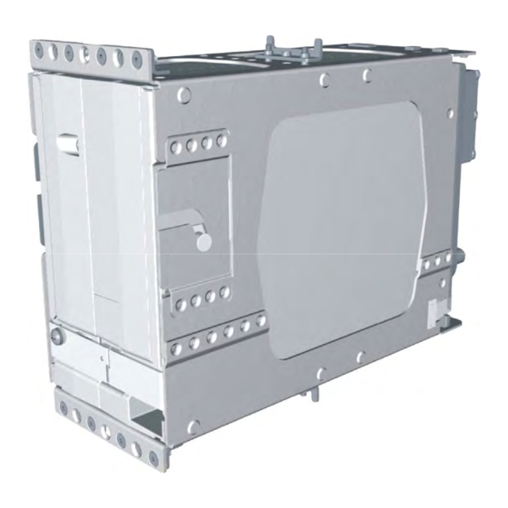
Figure B-2 are to be used when mounting the GIA 63(W) modular rack outside of the G1000 system rack. Aircraft manufacturer must fabricate any additional mounting equipment needed, use outline and installation drawings in Appendix B for reference. Figure 2-2 GIA 63(W) Modular Rack GIA 63/GIA 63W Installation Manual Page 2-13 190-00303-05 Revision S... -
Page 55: Gia 63(W) Standalone Rack
After the cable assemblies are made and wiring installed to the rack back plate, route wiring bundle as appropriate. Use cable ties to secure the cable assemblies and coax to provide strain relief for the cable assemblies. Figure 2-3 GIA 63(W) Standalone Rack Page 2-14 GIA 63/GIA 63W Installation Manual Revision S 190-00303-05... -
Page 56: Gia 63(W) Standalone Rack, Suggested Mounting Locations
Figure 2-4 GIA 63(W) Standalone Rack, Suggested Mounting Locations GIA 63/GIA 63W Installation Manual Page 2-15 190-00303-05 Revision S... - Page 57 This page intentionally left blank Page 2-16 GIA 63/GIA 63W Installation Manual Revision S 190-00303-05...
-
Page 58: Installation Procedure
If the unit is damaged, notify the carrier and file a claim. To justify a claim, save the original shipping container and all packing materials. Do not return the unit to Garmin until the carrier has authorized the claim. -
Page 59: Antenna Installation
NOTES 1. Non-Garmin part numbers shown are not maintained by Garmin and consequently are subject to change without notice. 2. Extraction of 16 and 18 AWG contacts requires cutting off the wire barrel from the contact. It may also be necessary to push the pin out from the face of the connector when using an extractor. -
Page 60: Backshell Assembly
3.5 Backshell Assembly The GIA 63(W) connector kit includes six Garmin backshell connectors. The backshell assemblies house the configuration module/temperature sensor, if applicable. Garmin’s backshell also gives the installer the ability to easily terminate shield grounds at the backshell housing using one of two methods available (SPIDER or Shield Block). -
Page 61: Post Installation Configuration & Checkout
3.7 Post Installation Configuration & Checkout All configuration and checkout procedures take place upon completion of the installation of the Garmin Integrated Flight Deck. The GDU serves as the graphics user interface to the installer configuring the system. For sample configuration and checkout procedures, refer to the G1000 Line Maintenance and Configuration Manual, Garmin part number 190-00303-04. -
Page 62: Gia Status Page
NOTE In order to comply with this procedure GIA 63 main software version must be 5.30 or later, GIA 63W main software version must be 5.21 or later, and GDU main software version must be 7.10 or later. 1. Verify the air temperature around both GIA’s is at least 70° Fahrenheit. - Page 63 This page intentionally left blank Page 3-6 GIA 63/GIA 63W Installation Manual Revision S 190-00303-05...
-
Page 64: System Interconnects
SPARE AIRCRAFT POWER 2 SPARE AIRCRAFT POWER 2 SPARE AIRCRAFT POWER 2 RESERVED RESERVED POWER GROUND POWER GROUND RESERVED RESERVED RESERVED * Indicates Active Low † Pin not currently supported GIA 63/GIA 63W Installation Manual Page 4-1 190-00303-05 Revision S... - Page 65 Connector P601, continued Pin Name RESERVED RESERVED RESERVED RESERVED RESERVED RESERVED RESERVED RESERVED POWER GROUND POWER GROUND * Indicates Active Low † Pin not currently supported Page 4-2 GIA 63/GIA 63W Installation Manual Revision S 190-00303-05...
- Page 66 ILS ENERGIZE* RESERVED RESERVED GLIDESLOPE +FLAG PARALLEL DME 1 MHZ-D GLIDESLOPE +UP VOR/ILS ARINC 429 IN B VOR/ILS ARINC 429 IN A * Indicates Active Low † Pin not currently supported GIA 63/GIA 63W Installation Manual Page 4-3 190-00303-05 Revision S...
- Page 67 GLIDESLOPE +DOWN (NAV COMMON) (011-01105-20 ONLY) PARALLEL DME 1MHZ-E RESERVED SPARE GLIDESLOPE COMPOSITE OUT (011-01105-20 ONLY) VOR/LOC DIGITAL AUDIO OUT SIGNAL GROUND POWER GROUND POWER GROUND * Indicates Active Low † Pin not currently supported Page 4-4 GIA 63/GIA 63W Installation Manual Revision S 190-00303-05...
- Page 68 MAIN ARINC 429 IN 2 A CAN BUS 1 TERMINATION MAIN ARINC 429 IN 2 B RS-485 5 A/RS-422 OUT A * Indicates Active Low † Pin not currently supported GIA 63/GIA 63W Installation Manual Page 4-5 190-00303-05 Revision S...
- Page 69 MAIN ARINC 429 OUT 2 A MAIN ARINC 429 OUT 3 B MAIN ARINC 429 OUT 3 A ETHERNET IN A ETHERNET IN B RESERVED * Indicates Active Low † Pin not currently supported Page 4-6 GIA 63/GIA 63W Installation Manual Revision S 190-00303-05...
- Page 70 ANNUNCIATE* 6 ANNUNCIATE* 7 ANNUNCIATE* 8 ANNUNCIATE* 9 ANNUNCIATE* 10 ANNUNCIATE* 11 ANNUNCIATE* 12 ANNUNCIATE* 13 ANNUNCIATE* 14 ANNUNCIATE* 15 ANNUNCIATE* 16 * Indicates Active Low † Pin not currently supported GIA 63/GIA 63W Installation Manual Page 4-7 190-00303-05 Revision S...
- Page 71 Connector P604, continued Pin Name ANNUNCIATE* 17 ANNUNCIATE* 18 ANNUNCIATE* 19 ANNUNCIATE* 20 ANNUNCIATE* 21 * Indicates Active Low † Pin not currently supported Page 4-8 GIA 63/GIA 63W Installation Manual Revision S 190-00303-05...
- Page 72 AIRCRAFT POWER 1 POTENTIOMETER REF OUT HI† AIRCRAFT POWER 2 POTENTIOMETER REF OUT LO (GROUND)† AIRCRAFT POWER 2 GIA REMOTE POWER OFF * Indicates Active Low † Pin not currently supported GIA 63/GIA 63W Installation Manual Page 4-9 190-00303-05 Revision S...
- Page 73 DISCRETE OUT* 4A ANNUNCIATE* 1A ANNUNCIATE* 2A DISCRETE IN* 17A DISCRETE IN 24A SUPERFLAG 2A POWER GROUND SUPERFLAG 3A POWER GROUND * Indicates Active Low † Pin not currently supported Page 4-10 GIA 63/GIA 63W Installation Manual Revision S 190-00303-05...
- Page 74 SPARE SPARE RESERVED SIGNAL GROUND RESERVED ADF DC REF IN RESERVED ANALOG ROLL STEERING HI RESERVED ANALOG ROLL STEERING LO (GROUND) * Indicates Active Low † Pin not currently supported GIA 63/GIA 63W Installation Manual Page 4-11 190-00303-05 Revision S...
- Page 75 DISCRETE OUT* 4B DISCRETE OUT* 5B DISCRETE OUT* 6B DISCRETE OUT* 7B DISCRETE OUT* 8B DISCRETE OUT* 9B RESERVED DISCRETE OUT* 10B RESERVED * Indicates Active Low † Pin not currently supported Page 4-12 GIA 63/GIA 63W Installation Manual Revision S 190-00303-05...
-
Page 76: Power And Antennas
Source current is internally limited to 1.5 mA max for a 10-33VDC input 4.2.1.3 Antennas Pin Name Connector GPS ANTENNA P611 COM ANTENNA P612 VOR/LOC ANTENNA P613 GLIDESLOPE ANTENNA P614 GIA 63/GIA 63W Installation Manual Page 4-13 190-00303-05 Revision S... -
Page 77: Gia System Id Program
P603 MAIN RS-232 OUT 8 P603 The RS-232 outputs conform to EIA Standard RS-232C with an output voltage swing of at least ± 5V when driving a standard RS-232 load. Page 4-14 GIA 63/GIA 63W Installation Manual Revision S 190-00303-05... - Page 78 P602 VOR/ILS ARINC 429 IN A P602 The MAIN and VOR/ILS ARINC 429 outputs conform to ARINC 429 electrical specifications when loaded with up to 5 standard ARINC 429 receivers. GIA 63/GIA 63W Installation Manual Page 4-15 190-00303-05 Revision S...
- Page 79 P603 This Ethernet based high speed data bus (HSDB) provides communications capability with the GDU. HSDB meets the hardware aspects of IEEE standard 802.3 for 10 base T Ethernet communications. Page 4-16 GIA 63/GIA 63W Installation Manual Revision S 190-00303-05...
-
Page 80: Discrete I/O
Leakage current in the INACTIVE state is typically ≤ 250 uA to ground ACTIVE: Vout ≤ 0.5VDC with ≤ 5 00 mA sink current Sink current must be externally limited to 500 mA max GIA 63/GIA 63W Installation Manual Page 4-17 190-00303-05... -
Page 81: Com/Vor/Ils/Digital Audio
The microphone gain adjustment is accessible through the top cover. When a 125 mV signal at 1000 Hz is applied to the INTERCOM MIC input, the level on the COM AUDIO output is not less than 7.07 V Page 4-18 GIA 63/GIA 63W Installation Manual Revision S 190-00303-05... - Page 82 4.6.2.6 Marker Beacon Pin Name Connector OUTER MARKER LAMP IN P605 MIDDLE MARKER LAMP IN P605 AIRWAY/INNER MARKER LAMP IN P605 Active high inputs used for outer/middle/inner marker lamp inputs. GIA 63/GIA 63W Installation Manual Page 4-19 190-00303-05 Revision S...
-
Page 83: Vor/Ils Indicator
The deviation outputs are each capable of driving up to three 1000 Ω meter loads with ±150 mV ±10% with respect to 2.5V Common for full-scale deflection. The drive circuit provides for more than full-scale ±10%. deflection with a maximum course deviation output voltage of ±300 mV Page 4-20 GIA 63/GIA 63W Installation Manual Revision S 190-00303-05... - Page 84 OBS STATOR D and VOR OBS STATOR F are each phase and amplitude shifted version of the VOR ROTOR C output. Each pair is intended to read one of the two windings of the indicator’s OBS stator. GIA 63/GIA 63W Installation Manual Page 4-21...
- Page 85 Leakage current in the INACTIVE state is typically ≤ 10 uA to ground ACTIVE: Vout ≤ 0.5VDC with ≤ 2 0 mA sink current Sink current must be externally limited to 20 mA max Page 4-22 GIA 63/GIA 63W Installation Manual Revision S 190-00303-05...
-
Page 86: Rmi/Obi
Leakage current in the INACTIVE state is typically ≤ 10 uA to ground ACTIVE: Vout ≤ 0.5VDC with ≤ 2 0 mA sink current Sink current must be externally limited to 20 mA max GIA 63/GIA 63W Installation Manual Page 4-23 190-00303-05... -
Page 87: Dme Tuning And Adf
INACTIVE: 10 ≤ V in ≤ 3 3VDC or Rin ≥ 100kΩ ACTIVE: Vin ≤ 1.9VDC with ≥ 7 5 uA sink current, or Rin ≤ 375Ω Sink current is internally limited to 200 uA max for a grounded input Page 4-24 GIA 63/GIA 63W Installation Manual Revision S 190-00303-05... - Page 88 -8 Vdc to +8 Vdc Input Impedance: > 80 kΩ Range: 0 to 360 degrees Resolution: ±0.1 degree or better Accuracy: ±3.0 degrees DC Reference Input: 0 to 5 Vdc maximum (>40 kΩ) GIA 63/GIA 63W Installation Manual Page 4-25 190-00303-05 Revision S...
-
Page 89: Auto Pilot
PITCH +DOWN. Otherwise the input voltage is negative. The input voltage is positive if FLIGHT DIRECTOR ROLL +RIGHT is greater than FLIGHT DIRECTOR ROLL +LEFT. Otherwise the input voltage is negative. Page 4-26 GIA 63/GIA 63W Installation Manual Revision S 190-00303-05... - Page 90 -15 to +15 Vdc Load Impedance: > 5 kΩ Scaling: 0.21 Vdc per degree of course error Range: 0 ± 71 degrees Resolution: ± 0.15° or better Accuracy: ± 1° GIA 63/GIA 63W Installation Manual Page 4-27 190-00303-05 Revision S...
- Page 91 ) when the flag is to be OUT OF VIEW. The output voltage with respect to ground is less than 0.25 V when the flag is to be IN VIEW. Page 4-28 GIA 63/GIA 63W Installation Manual Revision S 190-00303-05...
- Page 92 No pull-up resistors are required for the GIA 63W. NOTE The GIA 63W will function properly if the pull-up resistors are installed in the aircraft harness. GIA 63/GIA 63W Installation Manual...
- Page 93 This page intentionally left blank Page 4-30 GIA 63/GIA 63W Installation Manual Revision S 190-00303-05...
-
Page 94: Appendix A Gia 63 Main Boot Block Uploading Instructions
APPENDIX A GIA 63 MAIN BOOT BLOCK UPLOADING INSTRUCTIONS NOTE This appendix applies to the GIA 63 only, and does not apply to the GIA 63W. Introduction This appendix contains instructions on how to upgrade main boot block software for the GIA 63. Boot block version 4.01 is required for GIA Main Software Version 4.00 or later. -
Page 95: Loading Boot Block Version 4.01
9. Press the LOAD softkey. 10. Press the ENT key at the “BEGIN FILE UPLOAD?” prompt. CAUTION Do not turn power off or cancel the software upload while the boot block is loading. Page A-2 GIA 63/GIA 63W Installation Manual Revision S 190-00303-05... -
Page 96: Loading Gia Main Software (Only If Gia Main Software Was Cancelled In Section
8. Use the FMS knob to highlight GIA 6X software. 9. Press the LOAD softkey. 10. Press the ENT key at the “BEGIN FILE UPLOAD?” prompt. 11. Confirm update completion and press the ENT key. GIA 63/GIA 63W Installation Manual Page A-3 190-00303-05 Revision S... - Page 97 This page intentionally left blank Page A-4 GIA 63/GIA 63W Installation Manual Revision S 190-00303-05...
-
Page 98: Gia 63(W) Modular Installation Outline Drawing
MOUNTING HOLE FOR #6 FLAT HEAD 100 CSK SCREW (42 PLCS). .480 12.19 1.8 46 .44 11.1 .377 9.58 3.727 94.67 Figure B-1. GIA 63(W) Modular Installation Outline Drawing GIA 63/GIA 63W Installation Manual Page B-1 (Page B-2 blank) 190-00303-05 Revision S... -
Page 99: Gia 63(W) Modular Installation Drawing
GIA 63X RACK 115-00426-00 GIA 63X CONNECTOR KIT 011-01000-01 GIA 63X BACK PLATE KIT 011-00963-00 3-POSITION NUTPLATE KIT 011-00915-01 (PREFERRED WITH GARMIN SYSTEM RACK) 011-01148-01 (NOT SHOWN) QTY 2 NOTE: GIA 63 MINIMUM OF FOUR SCREWS REQUIRED PER NUTPLATE 011-00781-( ) -
Page 100: Gia 63(W) Standalone Installation Outline Drawing
MOUNTING HOLE FOR #8 PAN HEAD SCREW (4 PLCS). 2X .56 14.3 2X 4.458 113.23 2X 2.75 69.85 4X NOTE 4 Figure B-3. GIA 63(W) Standalone Installation Outline Drawing GIA 63/GIA 63W Installation Manual Page B-5 (Page B-6 blank) 190-00303-05 Revision S... -
Page 101: Gia 63(W) Standalone Installation Drawing
115-01239-00 GIA 63X CONNECTOR KIT 011-01000-01 GIA 63X BACK PLATE KIT 011-00963-00 GIA 63 011-00781-( ) GIA 63W 011-01105-( ) Figure B-4. GIA 63(W) Standalone Installation Drawing GIA 63/GIA 63W Installation Manual Page B-7 (Page B-8 blank) 190-00303-05 Revision S... -
Page 102: Appendix C Interconnect Examples
APPENDIX C INTERCONNECT EXAMPLES Figure C-1. GIA 63(W) Example Interconnect (Sheet 1 of 7) GIA 63/GIA 63W Installation Manual Page C-1 (Page C-2 blank) 190-00303-05 Revision S... -
Page 103: Gia 63(W) Example Interconnect (Sheet 2
APPENDIX C INTERCONNECT EXAMPLES Figure C-1. GIA 63(W) Example Interconnect (Sheet 2 of 7) GIA 63/GIA 63W Installation Manual Page C-3 (Page C-4 blank) 190-00303-05 Revision S... -
Page 104: Gia 63(W) Example Interconnect (Sheet 3
APPENDIX C INTERCONNECT EXAMPLES Figure C-1. GIA 63(W) Example Interconnect (Sheet 3 of 7) GIA 63/GIA 63W Installation Manual Page C-5 (Page C-6 blank) 190-00303-05 Revision S... -
Page 105: Gia 63(W) Example Interconnect (Sheet 4
APPENDIX C INTERCONNECT EXAMPLES Figure C-1. GIA 63(W) Example Interconnect (Sheet 4 of 7) GIA 63/GIA 63W Installation Manual Page C-7 (Page C-8 blank) 190-00303-05 Revision S... -
Page 106: Gia 63(W) Example Interconnect (Sheet 5
APPENDIX C INTERCONNECT EXAMPLES Figure C-1. GIA 63(W) Example Interconnect (Sheet 5 of 7) GIA 63/GIA 63W Installation Manual Page C-9 (Page C-10 blank) 190-00303-05 Revision S... -
Page 107: Gia 63(W) Example Interconnect (Sheet 6
APPENDIX C INTERCONNECT EXAMPLES Figure C-1. GIA 63(W) Example Interconnect (Sheet 6 of 7) GIA 63/GIA 63W Installation Manual Page C-11 (Page C-12 blank) 190-00303-05 Revision S... -
Page 108: Gia 63(W) Example Interconnect (Sheet 7
APPENDIX C INTERCONNECT EXAMPLES Figure C-1. GIA 63(W) Example Interconnect (Sheet 7 of 7) GIA 63/GIA 63W Installation Manual Page C-13 (Page C-14 blank) 190-00303-05 Revision S...