Table of Contents
Advertisement
Quick Links
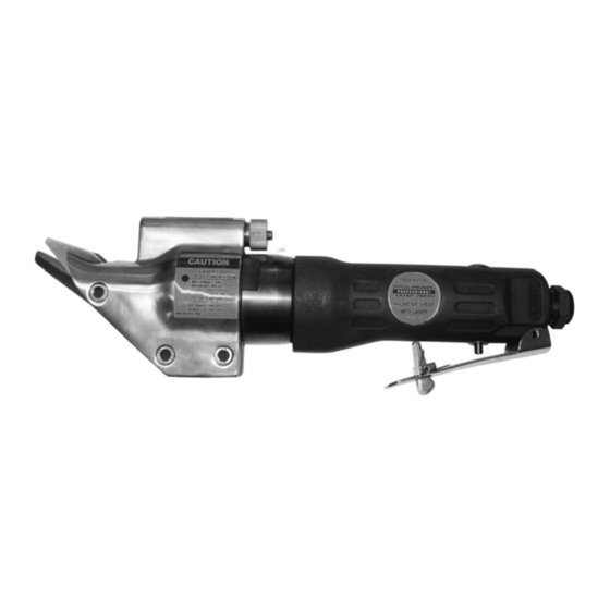
Laser In-LIne aIr shear
set up and OperatIng InstructIOns
distributed exclusively by harbor Freight tools
Visit our website at: http://www.harborfreight.com
read this material before using this product.
Failure to do so can result in serious injury.
saVe thIs manuaL.
©
Copyright
2008 by Harbor Freight Tools
contained herein may be reproduced in any shape or form without the express written consent of
Harbor Freight Tools. Diagrams within this manual may not be drawn proportionally. Due to continuing
improvements, actual product may differ slightly from the product described herein. Tools required for
assembly and service may not be included.
For technical questions or replacement parts, please call 1-800-444-3353.
REV 11h
3491 Mission Oaks Blvd., Camarillo, CA 93011
®
. All rights reserved. No portion of this manual or any artwork
65706
®
.
Advertisement
Table of Contents

Related Manuals for Central Pneumatic Professional Laser Series

Summary of Contents for Central Pneumatic Professional Laser Series
- Page 1 Laser In-LIne aIr shear 65706 set up and OperatIng InstructIOns ® distributed exclusively by harbor Freight tools 3491 Mission Oaks Blvd., Camarillo, CA 93011 Visit our website at: http://www.harborfreight.com read this material before using this product. Failure to do so can result in serious injury. saVe thIs manuaL.
-
Page 2: Safety Alert Symbol And Signal Words
saVe thIs manuaL cautIOn, used with the safety Keep this manual for the safety warn- alert symbol, ings and precautions, assembly, operat- indicates a hazardous ing, inspection, maintenance and cleaning situation which, if not procedures. Write the product’s serial avoided, could result in minor number in the back of the manual near the or moderate injury. -
Page 3: Personal Safety
do not operate the tool in explo- use safety equipment. A sive atmospheres, such as in the dust mask, non-skid safety presence of flammable liquids, shoes and a hard hat must gases, or dust. The tool is able to be used for the applicable create sparks resulting in the ignition conditions. -
Page 4: Air Source
service safer at the rate for which the tool is designed. Tool service must be performed do not use the tool if the switch only by qualified repair personnel. does not turn the tool on or off. When servicing a tool, use only Any tool that cannot be controlled identical replacement parts. -
Page 5: Specific Safety Instructions
sYmBOLs and cannot be built into this product, but must be supplied by the operator. specIFIc saFetY WARNING: The brass components InstructIOns of this product contain lead, a chemi- cal known to the State of California Symbol Definitions to cause birth defects (or other repro- ductive harm). - Page 6 physical symptoms related to vibra- tion (such as tingling, numbness, and white or blue fingers), seek medical advice as soon as possible. Do not smoke during use. Nico- tine reduces the blood supply to the hands and fingers, increasing the risk of vibration-related injury.
-
Page 7: Functional Description
FunctIOnaL descrIptIOn • This air tool may be shipped with a protective plug covering the air inlet. Remove this plug before set up. Specifications air supply Maximum Air 90 PSI Pressure tO preVent Air Inlet 1/4” -18 NPT expLOsIOn: Strokes per Minute* 2800 SPM use only clean, Air Consumption 9 SCFM @ 90 PSI... - Page 8 operation. Add a few more drops while checking the air output gauge after each hour of continual use. to set the right pressure range. Attach an air hose to the compres- Inspect the air connections for leaks. sor’s air outlet. Connect the air hose Repair any leaks found.
- Page 9 OperatIng InstructIOns putty and tighten enough to ensure an air-tight seal. read the entIre ImpOrtant This tool has a safety Trigger (9). saFetY InFOrmatIOn To depress the Trigger, you must section at the beginning of this first press the safety lock part of the manual including all text under Trigger out of the way.
- Page 10 general Operating Instructions Remove the clamps securing the work piece to the work table. If an automatic oiler is not used, If the tool requires more force to a few drops of Pneumatic Tool Oil accomplish the task, verify that the to the airline connection before use.
-
Page 11: User Maintenance Instructions
user-maIntenance cleaning, maintenance, and Lubrication InstructIOns note: These procedures are in addition to Procedures not specifically the regular checks and maintenance explained in this manual explained as part of the regular op- must be performed only by a eration of the air-operated tool. qualified technician. -
Page 12: Troubleshooting
If the Laser Light ceases to function, check the batteries. troubleshooting problem possible causes Likely solutions Decreased output. Not enough air pressure and/ Check for loose connections and make sure or air flow. that air supply is providing enough air flow (CFM) at required pressure (PSI) to the tool’s air inlet. -
Page 13: Parts List
parts LIst part # description QtY. part # description QtY. Gear Housing Spindle Valve Plug Gear Pin O-Ring Ball Bearing Spring Valve Spindle Washer O-Ring Ball Bearing Valve Spindle Eccentric Nut Cutter Housing Trigger Lock Screw End Plate Cap Right Blade Ball Bearing Left Blade Rear End Plate... -
Page 14: Assembly Diagram
assemBLY dIagram SKU 65706 For technical questions, please call 1-800-444-3353. Page 14... - Page 15 90 daY WarrantY Harbor Freight Tools Co. makes every effort to assure that its products meet high quality and durability standards, and warrants to the original purchaser that this product is free from defects in materials and workmanship for the period of 90 days from the date of purchase.