Table of Contents
Advertisement
Available languages
Available languages
Quick Links
Advertisement
Table of Contents

Related Manuals for 3Com 2800 Series


Summary of Contents for 3Com 2800 Series
- Page 1 3Com Baseline Switch 2800 Family (3CBLUG16A, 3CBLUG24A) User Guide...
-
Page 2: Table Of Contents
Table of Contents 1 Product Overview ..................1 Introduction .................... 1 Summary of Hardware Features ............1 Physical Features .................. 4 Front Panel ..................4 Rear Panel ..................4 Description of LEDs ................5 Technical Specifications ................ 6 Network Design ..................7 2 Installing The Switch ................ - Page 3 Informações de segurança importantes ..........31 Appendix B - Regulatory Information ............. 34 FCC Statement ................34 Information to the User ..............34 CE Statement (Europe) ............... 35 ICES Statement ................35 VCCI Statement ................36 Appendix C - Collection List of the Hazardous Substances ....37...
-
Page 4: Product Overview
Product Overview Introduction The 3Com Baseline Switch 2824 and the 3Com Baseline Switch 2816 are versatile, easy-to-use, unmanaged gigabit switches. It is ideal for users who want the high-speed performance of 10/100/1000 switching but do not need sophisticated management functions. The Switch is shipped ready for use, Operational straight out of the box. - Page 5 Table 1-1 Hardware Features Feature Description Auto-negotiation Supported on all ports. Forwarding Modes Store and Forward. Mac Address Table 2816: 32Gbps Port throughput 2824: 48Gbps Auto MDI/MDIX Supported on all ports. The Switch offers priority queuing, which means all packets that are received are examined to see if they have been priority encoded.
- Page 6 Feature Description The Switch has 24/16 10/100/1000 Mbps auto-negotiating ports. Each port automatically negotiates with the attached device to determine the correct speed and duplex mode of operation. Once negotiated, the port will operate in one of the following modes: 10BASE-T half duplex 10BASE-T full duplex 100BASE-TX half duplex...
-
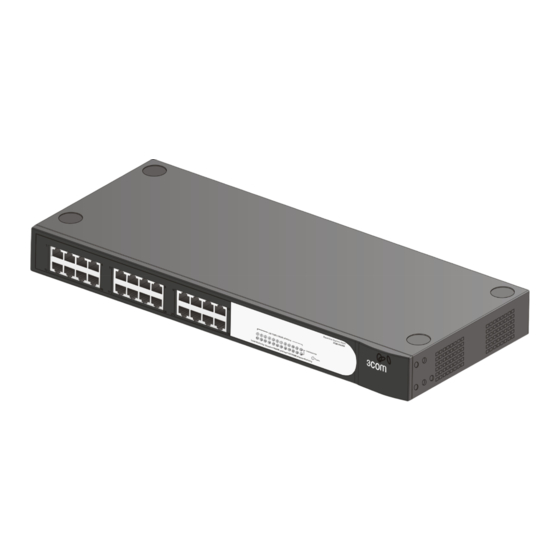
Page 7: Physical Features
Physical Features Front Panel Figure 1-2 2816 Figure 1-3 2824 Rear Panel Figure 1-4 Rear Panel... -
Page 8: Description Of Leds
Description of LEDs Table 1-2 Description of LEDs The Switch provides LED indicators on the front panel for your convenience to monitor the switch. Table 1-3 describes the meanings of the LEDs. Table 1-3 Description on the LEDs of the Switch Status Description The unit is powered on and ready for... -
Page 9: Technical Specifications
Technical Specifications Table 1-4 contains the technical specifications of the Switch. Table 1-4 Technical specifications of the Switch. Specification 2816 2824 Physical 44 mm×440 44 mm×440 dimensions mm×173 mm mm×173 mm (H×W×D) Weight <1.65 kg <1.75 kg Physical Ethernet port Free standing, or 19-inch rack Mounting mounted using the mounting kit... -
Page 10: Network Design
Specification 2816 2824 SO 8802-3, IEEE 802.3 (Ethernet), IEEE 802.3u (Fast Ethernet), IEEE 802.3ab (Gigabit Ethernet), IEEE 802.3x(Flow Functional control on full duplex links), IEEE 802.3d(Bridging), IEEE 802.1 p (VLAN tagging/ priority queuing) Related UL 60950-1, IEC60950-1, CSA Safety Standards 22.2 #60950-1, EN 60950-1 EN 55022 Class A, FCC Part 15 Subpart B Class A, ICES-003... - Page 11 Figure 1-5 Network Design...
-
Page 12: Installing The Switch
Installing The Switch WARNING: Safety Information. Before you install or remove any components from the Switch or carry out any maintenance procedures, you must read the safety information in Appendix A: Safety Information in this guide. AVERTISSEMENT: Consignes de sécurité. Avant d'installer ou d'enlever tout composant de Switch ou d'entamer une procédure de maintenance, lisez les informations relatives à... -
Page 13: Package Contents
OSTRZE ENIE: Informacje o zabezpieczeniach. Przed instalacją lub usunięciem jakichkolwiek elementów z product lub przeprowadzeniem prac konserwacyjnych nale y zapoznać się z informacjami o bezpieczeństwie zawartymi w Załączniku A niniejszego podręcznika. ADVERTÊNCIA: Informações de segurança Antes de instalar ou remover quaisquer componentes do Switch ou de executar quaisquer procedimentos de manutenção, leia as informações de segurança no Appendix A: Safety Information deste guia. -
Page 14: Rack Mounting
Water or moisture cannot enter the case of the switch. Air flow is not restricted around the switch or through the vents in the side of the switch. 3Com recommends that you provide a minimum of 25 mm (1 in.) clearance. - Page 15 Disconnect all cables from the switch before continuing. Remove all self adhesive pads from the underside of the switch if they have been fitted. If you use a shelf or support ensure that it will not obstruct the air flow through the side panels of the switch. To rack-mount the switch: 1) Place the switch the right way up on a hard flat surface, with the front facing towards you.
-
Page 16: Powering On
You must use the screws supplied with the securing brackets. Damage caused to the unit by using incorrect screws invalidates your warranty. 4) Repeat steps 2 and 3 for the other side of the switch. 5) Insert the switch into the 19-inch rack and secure with suitable screws. -
Page 17: Problem Solving
Problem Solving At regular intervals you should visually check the Switch. Regular checks can give you an early warning of a possible failure; any problems can then be attended to when there will be least effect on users. Check that all external cabling connections are secure and that no cables are pulled taut. - Page 18 If the problem persists and the unit still does not operate successfully, contact your supplier with the following information before returning the unit: 1) Product number and serial number (printed on a label supplied with the unit). 2) A brief description of the fault condition.
-
Page 19: Obtaining Support For Your Product
Warranty and other service benefits are enabled through product registration. Register your product at http://eSupport.3com.com/. 3Com eSupport services are based on accounts that you create or have authorization to access. First time users must apply for a user name and password that provides access to a number of eSupport features including Product Registration, Repair Services, and Service Request. -
Page 20: Troubleshoot Online
A list of system hardware and software, including revision level Diagnostic error messages Details about recent configuration changes, if applicable To send a product directly to 3Com for repair, you must first obtain a return authorization number (RMA). Products sent to 3Com, without... - Page 21 If your product is registered and under warranty, you can obtain an RMA number online at http://eSupport.3com.com/. First time users will need to apply for a user name and password.
- Page 22 You can also obtain support in this region using the following: Spanish speakers, enter the URL: http://lat.3com.com/lat/support/form.html Portuguese speakers, enter the URL: http: //lat. 3com. com/br/support/form.html English speakers in Latin America should send e-mail to: lat_support_anc@3com.com US and Canada Telephone Technical Support and Repair 1 800 876 3266...
-
Page 23: Appendix A - Safety Information
Appendix A - Safety Information Safety Information Please read the following safety information carefully before installing the Switch. Installation and removal of the unit must be carried out by qualified personnel only. If installing the Switch unit in a stack with other Baseline units, the Switch must be installed below the narrower Hub units. - Page 24 These ports are shielded RJ-45 data sockets. They cannot be used as standard traditional telephone sockets or to connect the unit to a traditional PBX or public telephone network. Connect only RJ-45 data connectors, network telephony systems, or network telephones to these sockets. Either shielded or unshielded data cables with shielded or unshielded jacks can be connected to these data sockets.
-
Page 25: L'information De Sécurité Importante
Switzerland The supply plug must comply with SEV/ASE 1011. L’information de Sécurité Importante L’installation et la dépose de ce groupe doivent être confiés à un personnel qualifié. Si vous entassez l’unité Switch avec les unités Baseline, l’unité Switch doit être installée en dessous des unités Hub plus étroites. - Page 26 Ceux-ci sont protégés par desprises de données. Ils ne peuvent pas être utilisés comme prises detéléphone conventionnelles standard, ni pour la connection de l’unité à un réseau téléphonique central privé ou public. Raccorder seulement connecteurs de données RJ-45, systèmes de réseaux de téléphonie ou téléphones de réseaux à...
-
Page 27: Wichtige Sicherheitsinformationen
Wichtige Sicherheitsinformationen Die Installation und der Ausbau des Geräts darf nur durch Fachpersonal erfolgen. Wenn der Switch mit anderen 3Com Hubs oder Switch gestackt werden soll, müssen grössere Geräte unter den schmaleren Hubs eingebaut werden. Das Gerät muß geerdet sein. -
Page 28: Información De Seguridad Importante
Diese Porte sind geschützte Datensteckdosen. Sie dürfen weder wie normale traditionelle Telefonsteckdosen noch für die Verbindung der Einheit mit einem traditionellem privatem oder öffentlichem Telefonnetzwerk gebraucht werden. Nur RJ-45-Datenanscluße, Telefonnetzsysteme or Netztelefone an diese Steckdosen anschließen. Entweder geschützte oder ungeschützte Buchsen dürfen an diese Datensteckdosen angeschlossen werden. - Page 29 al que esté conectada la unidad también cumple los requisitos SELV. Sólo para Francia y Perú: † Esta unidad no puede recibir corriente de fuentes IT . Si las fuentes de suministro de corriente son de tipo IT, esta unidad debe recibir 230 V (2P+T) a través de un transformador aislador con relación 1:1, con el punto de conexión secundario etiquetado como neutro conectado directamente a tierra.
-
Page 30: Importanti Informazioni Di Sicurezza
El conjunto de cables debe estar EE.UU. y homologado por UL y tener la certificación Canadá CSA. La especificación mínima del cable flexible Nº 18 AWG Tipo SV o SJ Tres conductores El conjunto de cables debe tener una capacidad de corriente nominal de al menos 10 A. - Page 31 Per rispettare gli standard di sicurezza, è necessario collegare l'unità a una fonte di alimentazione dotata di messa a terra. L'accoppiatore (il connettore all'unità e non la spina a muro) deve avere una configurazione abbinabile a una presa EN60320/IEC320. La presa deve trovarsi vicino all'unità ed essere facilmente accessibile.
-
Page 32: Wa Ne Informacje O Zabezpieczeniach
Il cavo deve avere l'approvazione UL e la Stati Uniti e certificazione CSA Canada La specifica minima per il cavo flessibile è: N. 18 AWG Tipo SV o SJ 3 conduttori Il set di cavi deve avere una capacità nominale di almeno 10 A. La spina di collegamento deve essere dotata di messa a terra, con configurazione NEMA 5-15P (15 A, 125 V) o NEMA 6-15P (15 A,... - Page 33 Złączka urządzenia (podłączona do przełącznika, a nie do wtyczki ściennej) musi być odpowiednio dopasowana do normy EN60320/IEC320 otworu wlotowego. Gniazdo zasilające musi być umieszczone w pobli u urządzenia i musi być łatwo dostępne. Odłączenie zasilania od urządzenia mo e nastąpić tylko przez odłączenie przewodu zasilającego. Urządzenie to pracuje w warunkach SELV (Safety Extra Low Voltage –...
-
Page 34: Informações De Segurança Importantes
Zestaw przewodów musi posiadać Stany zezwolenie UL oraz certyfikat CSA. Zjednoczone i Minimalna specyfikacja przewodu giętkiego: Kanada Przewód typu SV lub SJ 3 o średnicy 18 wg specyfikacji AWG. Zestaw przewodów musi posiadać pojemność prądu znamionowego przynajmniej 10A. Wtyczka musi być uziemiająca z układem typu NEMA 5-15P (15A, 125V) lub NEMA 6-15P (15A, 250V). - Page 35 Conectar a unidade a uma fonte de alimentação aterrada para cumprir os padrões de segurança. O acoplador do aparelho (a peça que faz a conexão com a unidade e não o conector com a tomada da parede) deve ser configurado para compatibilidade com a entrada do aparelho de padrão EN60320/IEC320.
- Page 36 O cabo de alimentação deve ser aprovado E.U.A. e pelo UL e certificado pela CSA. Canadá A especificação mínima do cabo flexível é a seguinte: No. 18 AWG Tipo SV or SJ 3-fios O conjunto do cabo deve ter capacidade nominal para corrente de 10A, no mínimo.
-
Page 37: Appendix B - Regulatory Information
Appendix B - Regulatory Information FCC Statement This equipment has been tested and found to comply with the limits for a Class A digital device, pursuant to part 15 of the FCC rules. These limits are designed to provide reasonable protection against harmful interference when the equipment is operated in a commercial environment. -
Page 38: Ce Statement (Europe)
Washington, DC 20402, Stock No. 004-000-00345-4. In order to meet FCC emissions limits, this equipment must be used only with cables which comply with IEEE 802.3. CE Statement (Europe) EU Representative: 3Com Europe Limited Peoplebuilding 2, Peoplebuilding Estate Maylands Avenue Hemel Hempstead, Hertfordshire HP2 4NW... -
Page 39: Vcci Statement
VCCI Statement... -
Page 40: Appendix C - Collection List Of The Hazardous Substances
Appendix C - Collection List of the Hazardous Substances 有 毒 有 害 物 质 或 元 素 Hazardous Substances 部 件 名 称 多 溴 多 溴 二 Parts Name 铅 汞 镉 六 价 铬 联 苯 苯 醚 PBDE PCBA 焊... - Page 41 有 毒 有 害 物 质 或 元 素 Hazardous Substances 部 件 名 称 多 溴 多 溴 二 Parts Name 铅 汞 镉 六 价 铬 联 苯 苯 醚 PBDE 、 荧 光 管 、 电 子 元 器 件...
- Page 42 “ ” SJ/T 11363-2006 × × × × RoHS 2002/95/EC 2005/717/EC 2005/747/EC 2006/310/EC 2006/690/EC 2006/691/EC 2006/692/EC The “ × × × × ” sign indicates that the marked substance does not satisfy the “Requirements for Concentration Limits for Certain Hazardous Substances in Electronic Information Products SJ/T 11363-2006”, but it is listed in the exemption list specified by the related EU RoHS Directive, including 2002/95/EC, 2005/717/EC, 2005/747/EC, 2006/310/EC, 2006/690/EC,...