Table of Contents
Advertisement
Advertisement
Table of Contents

Related Manuals for 3Com 2816-SFP Plus (3C16485)


Summary of Contents for 3Com 2816-SFP Plus (3C16485)
- Page 1 ® 3Com Baseline Switch 2816-SFP Plus (3C16485) User Guide DUA1648-5AAA02...
- Page 2 LICENSE.TXT. If you are unable to locate a copy, please contact 3Com and a copy will be provided to you.
-
Page 3: Table Of Contents
Conventions Feedback about this User Guide Product Registration Introduction Baseline Switch 2816-SFP Plus Package Contents How to Use the Baseline Switch 2816-SFP Plus Front and Rear Panels Front Panel Features Rear Panel Features Installation Recommendations Positioning the Switch Rack Mounting or Free Standing... - Page 4 Membership VLANs Trunking Traffic Monitoring System Tools Restart Configuration Upgrade Spanning Tree 802.1p Prioritization Support Using Discovery Running the Discovery Application Windows Installation (95/98/XP/2000/2003 Server/NT) Problem Solving Safety Information L'INFORMATION DE SÉCURITÉ IMPORTANTE WICHTIGE SICHERHEITSINFORMATIONEN Technical Information Related Standards Environmental Physical Electrical Technical Support...
-
Page 5: About This Guide
LANs (Local Area Networks). If a release note is shipped with this 3Com Baseline Switch 2816-SFP Plus and contains information that differs from the information in this guide, follow the information in the release note. -
Page 6: Feedback About This User Guide
For information about contacting Technical Support, please refer to “Support” on page 37. The Switch is part of the extensive Baseline range of 3Com prod- ucts. This range includes hubs, switches, power systems and other networking equipment, and is continually being devel- oped. -
Page 7: Introduction
This offers you the flexibility of using SFP transceivers to provide connectivity between the Switch and a 1000 Mbps core network. The Switch is suitable for office use where it can be free-standing, or rack mounted (in a wiring closet or equipment room). -
Page 8: Package Contents
Package Contents The Switch comes with: One power cord Four standard height, self-adhesive rubber pads One mounting kit Installation CD This User Guide Warranty flyer The Switch is powered from the AC supply. -
Page 9: How To Use The Baseline Switch 2816-Sfp Plus
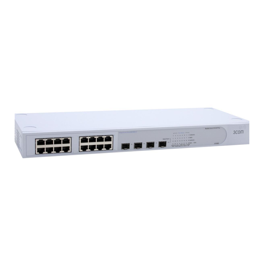
OW TO SE THE Front and Rear Panels The front panel of the Switch contains a series of indicator lights (LEDs) that help describe the state of various networking and connection operations. The numbers in this diagram refer to numbered sections in “Front Panel Features”... - Page 10 (even if the attached device is operating in full duplex mode). In such a configuration, you may notice some degradation of network performance. 3Com recommends that you use devices that are capable of auto-negotiation (and that you ensure that auto-negotiation is enabled, if it is a configurable option).
-
Page 11: Rear Panel Features
Flashing Power-on self test is in progress. Green Yellow Power-on self test or loopback test failed. Switch is in fail- safe mode. 7 Self-adhesive Pads The unit is supplied with four self-adhesive rubber pads. Do not apply the pads if you intend to rack mount the unit. - Page 12 CAUTION: 3Com recommends that you back up your configuration settings before you recover the Switch, otherwise your configuration will be lost. Refer to “Configuration” on page 33 for details.
-
Page 13: Installation Recommendations
Water or moisture cannot enter the case of the unit. Air flow around the unit and through the vents in the side of the case is not restricted (3Com recommends that you provide a minimum of 25 mm (1 in.) clearance). -
Page 14: Spot Checks
100 m (328 ft). Connect one end of the cable to an RJ-45 port on the Switch and the other end to the appropriate RJ-45 port on the connecting device. 3Com recommends the use of Category 5e or 6 cables for 1000BASE-T operation. SFP Operation The following sections describe how to insert an SFP transceiver into an SFP slot. -
Page 15: Removing An Sfp Transceiver
Use of non-3Com SFPs is not recommended. If the SFP transceiver is invalid it will not be recognised by the Switch. Use the following sequence of steps to activate the SFP ports: Hold the transceiver so that the fiber connector is toward you and the product label is visible, as shown in wire release lever is closed (in the upright position). -
Page 17: Mounting Kit Instructions
“Positioning the Switch” on page 13. Rack Mounting the Units The Switch is 1U high and will fit in a standard 19-inch rack. CAUTION: Disconnect all cables from the unit before continuing. Remove the self-adhesive pads from the underside of unit, if already fitted. -
Page 19: Automatic Ip Configuration
Switch’s MAC address in the DHCP server’s lease list. Refer to “IP Settings” on page 23. 3Com recommends that you do not use DHCP Addressing, unless you have experience of configuring and managing a DHCP server. How Automatic IP Configuration Works... - Page 20 The Switch repeats step 2 until an unused IP address is found.
-
Page 21: Switch Configuration
URL is http://169.254.x.y., where x and y are assigned by the process described in “How Automatic IP Configuration Works” on page 19. If you changed the Switch LAN IP address during initial configuration, use the new IP address instead. When you have browsed to the Switch, log in using your system password. -
Page 22: Fan Status
6. At the right hand side of the panel Figure 7 Summary Screen under the 3Com company name is an image depicting two fans. These represent the Switch’s fans and their current status. A green fan indicates normal operation, a red fan indicates that the fan has failed to start. -
Page 23: Password
The password is case sensitive. IP Settings The IP Settings menu allows you to view and amend your Switch’s IP settings. Figure 9 IP Settings Screen Management VLAN — This is the only VLAN through which you can gain management access to the Switch. -
Page 24: Port Configuration
IP configuration, manual configuration (static) or dynamically using DHCP (Dynamic Host Configuration Protocol). IP Address — The IP address of the Switch, and the address of the default VLAN (VLAN1). Subnet Mask — This mask identifies the host address bits used for routing to specific subnets. -
Page 25: Vlans
Packet Rate Threshold — Shows the broadcast storm threshold. (500 - 15000 packets per second) VLANs The Switch uses VLANs to organise any group of ports into separate broadcast domains. VLANs confine broadcast traffic to the originating group and can eliminate broadcast storms in large networks. -
Page 26: Vlan Configuration Examples
VLAN 2 This example explains how you can set up a simple VLAN Configuration on your Switch using desktop connections. If you want to add ports 7, 8 and 16 to VLAN2, as shown in Figure 12, so that the ports on the default VLAN1 and the ports on VLAN2... - Page 27 To set up the configuration shown in Figure 13, do the following: Use the Create VLANs screen (Figure 14) to create VLAN2 on both Switch 1 and Switch 2, and assign the same name to it. (VLAN1 is the default VLAN and already exists.)
-
Page 28: Create Vlans
Create VLANs Use the Create VLANs page to set up VLANs. To propagate information about VLAN groups used on this switch to external devices, you must specify a VLAN ID for each of these groups. Figure 14 Create VLANs Screen VLAN ID —... -
Page 29: Modify Vlans
VLANs, or only with a selected VLAN. Uplink - if you select this, the port is able to communicate with all VLANs on the Switch. Desktop - if you select this, the port can only communi- cate with other ports assigned to the VLAN selected in the VLAN ID drop down list. -
Page 30: Trunking
Guidelines for creating Trunks Any of the ports on the Switch can be used for creating a trunk. This switch can support a maximum of 4 trunks. Each trunk may contain up to 8 members. - Page 31 Use the Trunking Membership page to add ports to a group membership. Figure 19 Trunking Membership Screen Port — The port number. Status — The status refers to the speed and duplex mode of the trunk members. Trunk — ID of trunk. Use the Trunking Summary page to display all of the configuration settings for the created trunks.
-
Page 32: Traffic Monitoring
Restart, Configuration, Upgrade, Spanning Tree and 802.1p Prioritization. Restart Pressing the Restart the Switch button has the same effect as power cycling the unit. No configuration information will be lost. This function may be of use if you are experiencing problems and you wish to re-establish your Internet connection. -
Page 33: Configuration
Upgrade The Upgrade facility allows you to install on the Switch any new releases of system software that 3Com may make available. The newer version of software can be downloaded via HTTP and once copied to the Switch; the Switch will restart and apply the newer system software version. - Page 34 The file will be copied to the Switch, and once this has completed, the Switch will restart. Although the upgrade process has been designed to preserve your configuration settings, 3Com recommends that you make a backup of the configuration beforehand, in case the upgrade process fails for any reason (for example, the connection between the computer and the Switch is lost while the new software is being copied to the Switch).
-
Page 35: Spanning Tree
The Switch does not forward BPDUs to other ports. The Switch does not participate as a bridge node in the spanning tree, it can only be configured to forward or block spanning tree BPDUs. If the Switch is connected to other bridging devices, such as switches, that are part of the spanning tree network, set the Switch to "Forward."... -
Page 36: 802.1P Prioritization
It differentiates traffic into classes and prioritizes those classes automatically. Traffic prioritization uses the multiple traffic queues that are present in the hardware of the Switch to ensure that high priority traffic is forwarded on a different queue from lower priority traffic, and is given preference over that traffic. -
Page 37: Support
Figure 27 802.1p Prioritization screen Support Selecting Support on the main menu displays the support links screen, which contains a list of Internet links that provide information and support concerning the Switch. (Figure Figure 28 Support Screen... -
Page 39: Using Discovery
SING ISCOVERY Running the Discovery Application 3Com provides a user-friendly Discovery application for detecting the Switch on the network. If your computers are configured with static addresses (also known as fixed addresses) and you do not wish to change this, then you should use the Discovery program on the Switch CD-ROM to detect and configure your Switch. - Page 40 LAN. Figure 30 Discovered Switch Figure 30 shows an example Discovered Devices screen. Highlight the Secure Switch by clicking on it, and click Next. Figure 31 Discovery Finish Screen 7UHF46B9C2A9C Click on Finish to launch a web browser and display the login...
-
Page 41: Problem Solving
The fiber cable is in good condition. The SFP module is correctly inserted. A 3Com SFP module is being used. Refer to “Approved SFP Transceivers” on page 14 for details. The equipment at the far end is installed and correctly configured. - Page 42 Otherwise, you can restore the default settings, using the recovery button on the rear panel of the Switch. For details on how to use Discovery to detect the Switch on the network, refer to “Using Discovery” on page 39.
- Page 43 5 seconds, or when the LED flashes, release the recovery button. The Switch will now enter fail safe mode, whereby the Switch’s IP address, user name and password will be reset to the factory defaults. Click on the RESTART THE SWITCH button.
-
Page 45: Safety Information
WARNING: Installation and removal of the unit must be carried out by qualified personnel only. If installing the Switch unit in a stack with other units, the Switch unit must be installed below the narrower units and above the deeper units. -
Page 46: L'information De Sécurité Importante
AVERTISSEMENT: L’installation et la dépose de ce groupe doivent être confiés à un personnel qualifié. Si vous entassez l’unité Switch avec les unités SuperStack 3 Hub, l’unité Baseline Switch 2816-SFP Plus doit être installée en dessous des unités Hub plus étroites. -
Page 47: Wichtige Sicherheitsinformationen
WARNUNG: Die Installation und der Ausbau des Geräts darf nur durch Fachpersonal erfolgen. Wenn der Baseline Switch 2816-SFP Plus mit anderen 3Com Hubs oder Switche gestapelt werden soll, müssen grössere Geräte unter den schmaleren Hubs eingebaut werden. Das Gerät sollte nicht an eine ungeerdete Wechselstromsteckdose angeschlossen werden. -
Page 49: Technical Information
ECHNICAL NFORMATION Related Standards The Baseline Switch 2816-SFP Plus has been designed to the following standards: Functional ISO 8802-3, IEEE 802.3 (Ethernet), IEEE 802.3u (Fast Ethernet), IEEE 802.3ab and IEEE 802.3z (Gigabit Ethernet), IEEE 802.3x (Flow Control), IEEE 802.1D 1998... -
Page 51: Technical Support
3Com eSupport services are based on accounts that you create or have authorization to access. First time users must apply for a user name and password that provides access to a number of eSupport features including Product Registration, Repair Services, and Service Request. -
Page 52: Telephone Technical Support And Repair
Diagnostic error messages Details about recent configuration changes, if applicable Before you send a product directly to 3Com for repair, you must first obtain an authorization number. Products sent to 3Com, without authorization numbers clearly marked on the outside of the package, will be returned to the sender unopened, at the sender’s expense. - Page 53 Trinidad and Tobago Uruguay Venezuela Virgin Islands Telephone Number 1 800 988 2112 0 810 444 3COM 1 800 998 2112 1 800 998 2112 1 800 998 2112 52 5 201 0010 1 800 998 2112 1 800 998 2112...
- Page 54 Country Telephone Number You can also obtain support in this region using the following: Spanish speakers, enter the URL: http://lat.3com.com/lat/support/form.html Portuguese speakers, enter the URL: http://lat.3com.com/br/support/form.html English speakers in Latin America should send e-mail to: lat_support_anc@3com.com US and Canada Telephone Technical Support and Repair...
-
Page 55: Glossary
LOSSARY 10BASE-T The IEEE specification for 10 Mbps Ethernet over Category 3, 4 or 5 twisted pair cable. 100BASE-TX The IEEE specification for 100 Mbps Fast Ethernet over Category 5 twisted-pair cable. 1000BASE-LX IEEE 802.3z specification for Gigabit Ethernet over 9/125 micron core single-mode fiber cable. - Page 56 Category 5e Cables One of five grades of Twisted Pair (TP) cabling defined by the EIA/TIA-568 standard. Category 5e can be used in Ethernet (10BASE-T), Fast Ethernet (100BASE-TX) and Gigabit Ethernet (1000BASE-T) networks, and can transmit data at speeds of up to 1000 Mbps.
- Page 57 IEEE 802.1Q VLAN Tagging - Defines Ethernet frame tags which carry VLAN information. It allows switches to assign endstations to different virtual LANs, and defines a standard way for VLANs to communicate across switched networks. IEEE 802.1p An IEEE standard for providing quality of service (QoS) in Ethernet networks.
- Page 58 InterNIC). Subnets A network that is a component of a larger network. Switch A device that interconnects several LANs to form a single logical LAN that comprises of several LAN segments. Switches are similar to bridges, in that they connect LANs of a different type;...
- Page 59 Traffic Monitoring Enables the monitoring of port traffic by attaching a network analyzer to one switch port, in order to monitor the traffic of other ports on the Switch. Trunking A method which specifies how to create a single high-speed logical link that combines several lower-speed physical links.
-
Page 61: Index
1000BASE-SX 1000BASE-T 100BASE-TX 10BASE-T 802.1p Prioritization admin password changing 23 automatic IP configuration bandwidth Baseline Switch 2816-SFP Plus category 3 cables category 5 cables Category 5e Cables Category 6 Cables changing the admin password client configuring computers configuring the Switch... - Page 62 DHCP addressing 19 Discovery program 19 static IP configuration 19 IP defined IP Precedence ISP defined LAN defined LAN settings configuring 23 loading Switch configuration local area network MAC address main menu manual configuration media access control network defined obtaining support/feedback password...
- Page 63 Switch configuration server defined setting up computers subnet mask support Support for your product Switch changing the password 23 configuration 21 positioning 13 restarting 32 switch defined system tools TCP/IP defined 59 technical specifications traffic traffic prioritization upgrading firmware...
-
Page 65: Regulatory Notices
EGULATORY OTICES FCC Statement This equipment has been tested and found to comply with the limits for a Class A digital device, pursuant to Part 15 of the FCC Rules. These limits are designed to provide reasonable protection against harmful interference in a commerical environment. This equipment generates, uses and can radiate radio frequency energy and, if not installed and used in accordance with the instructions, may cause harmful interference to radio communications. - Page 66 Part Number: DUA1648-5AAA02 Published: September 2004...