Table of Contents
Advertisement
Available languages
Available languages
Quick Links
OPERATOR'S MANUAL
26 Gallon Portable Air Compressor
F226VWD / 585-819
Your air compressor has been engineered and manufactured to Husky's high standard for dependability,
ease of operation, and operator safety. When properly cared for, it will give you years of rugged, trouble-
free performance.
WARNING:
Thank you for buying a Husky product.
SAVE THIS MANUAL FOR FUTURE REFERENCE
To reduce the risk of injury, the user must read and understand the operator's manual before
using this product.
02/09/2009
Advertisement
Chapters
Table of Contents

Related Manuals for Husky F226VWD


Summary of Contents for Husky F226VWD
- Page 1 26 Gallon Portable Air Compressor F226VWD / 585-819 Your air compressor has been engineered and manufactured to Husky’s high standard for dependability, ease of operation, and operator safety. When properly cared for, it will give you years of rugged, trouble- free performance.
-
Page 2: Table Of Contents
If this compressor is altered in any way, existing warranties shall be voided. Husky and MAT Holdings, Inc. disclaim any liabilities whatsoever for any loss, personal injury, or damage. -
Page 3: General Safety Rules
GENERAL SAFETY RULES g The employer and/or user must ensure that proper eye protection is worn. We recommend a Wide Vision Safety WARNING Mask for use over eyeglasses or standard safety glasses Read and understand all instructions. Failure to follow all that provide protection against flying particles both from the instructions listed below may result in electric shock, fire, front and side. Always use eye protection which is marked and/or serious personal injury. to comply with ANSI Z87.1. - Page 4 GENERAL SAFETY RULES SERVICE g Maintain tools with care. Follow maintenance instructions. Properly maintained tools are easier to control. g Tool service must be performed only by qualified repair personnel. Service or maintenance performed by g Check for misalignment or binding of moving parts, unqualified personnel may result in a risk of injury.
-
Page 5: Specific Safety Rules
SPECIFIC SAFETY RULES g Never store tool with air connected. Storing the tool with g Know your power tool. Read operator’s manual carefully. Learn its applications and limitations, as well as the specific air connected can result in unexpected firing and possible potential hazards related to this tool. Following this rule will serious personal injury. reduce the risk of electric shock, fire, or serious injury. g Always follow all safety rules recommended by the g Drain tank of moisture after each day’s use. -
Page 6: Symbols
SYMBOLS Some of the following symbols may be used on this tool. Please study them and learn their meaning. Proper interpretation of these symbols will allow you to operate the tool better and safer. SYMBOL NAME DESIGNATION/EXPLANATION Volts Voltage Amperes Current Hertz Frequenct (cycles per second) - Page 7 SYMBOLS The following signal words and meanings are intended to explain the levels of risk associated with this product. SYMBOL SIGNAL MEANING Indicates an imminently hazardous situation, which, if not avoided, will result in death or DANGER serious injury. Indicates a potentially hazardous situation, which, if not avoided, could result in death or WARNING serious injury.
-
Page 8: Electrical
ELECTRICAL EXTENSION CORDS SPEED AND WIRING Use only 3-wire extension cords that have 3-prong grounding The no-load speed of this product is approximately 3,450 rpm. plugs and 3-pole receptacles that accept the product’s plug. This speed is not constant and decreases under a load or with When using a power tool at a considerable distance from the lower voltage. For voltage, the wiring in a shop is as impor- power source, use an extension cord heavy enough to carry tant as the motor’s horsepower rating. -
Page 9: Glossary Of Terms
GLOSSARY OF TERMS Air Filter Pressure Regulator Knob Porous element contained within a metal or plastic housing Regulates the outgoing pressure from the air outlet to the tool. attached to the compressor cylinder head which removes It is possible to increase or decrease the pressure at the outlet impurities from the intake air of the compressor. by adjusting this control knob. -
Page 10: Features
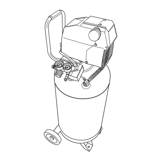
FEATURES PRODUCT SPECIFICATIONS Running Horsepower .............1.5 HP Lubrication ..............Oil-Free Air Tank Capacity ............26 gal. Gauges ............... 2 in. diameter Air Pressure ............150 psi max. Input........120 V, 60 Hz, AC Only, 15.0 Amps Air Delivery ..........4.0 SCFM @ 90 psi Net Weight ..............111.0 lbs. PRESSURE REGULATOR TANK PRESSURE GAUGE GAUGE HANDLE MOTOR RESET BUTTON PRESSURE AUTOMATIC / OFF REGULATOR KNOB PRESSURE RELIEF VALVE... -
Page 11: Assembly
FEATURES KNOW YOUR AIR COMPRESSOR See Figure 2. The safe use of this product requires an understanding of the information on the product and in this operator’s manual as well as a knowledge of the project you are attempting. Before use of this product, familiarize yourself with all operating features and safety rules. HANDLE PRESSURE RELIEF VALVE The air compressor is equipped with a padded carrying handle The pressure relief valve is designed to automatically release for ease of use. -
Page 12: Operation
OPERATION UNPACKING g Carefully remove the product from the box. Make sure that all items listed in the packing list are included. g Inspect the product carefully to make sure no breakage or damage occurred during shipping. g Do not discard the packing material until you have carfully inspected and satisfactorily operated the product. g If any parts are damaged or missing, please call 1-866-340-3912 for assistance. PACKING LIST Air compressor 1 Instruction manual 1 WARNING... - Page 13 OPERATION APPLICATIONS Air compressors are utilized in a variety of air system applications. Match hoses, connectors, air tools, and accessories to the capabilities of the air compressor. You may use this tool for the purposes listed below: g Operating some light duty air powered tools. g Inflating tires, air beds, sports equipment, etc. (Inflation accessories sold separately) OFF/AUTOMATIC TURNING THE AIR COMPRESSOR ON/OFF See Figure 4.
- Page 14 OPERATION WARNING Always disconnect the air supply and power supply before making adjustments, servicing a tool, or when a tool is not in use. DRAINING THE TANK See Figure 6-1, 6-2. To help prevent tank corrosion and keep moisture out of the air used, the tank of the compressor should be drained daily.
- Page 15 OPERATION CHECKING THE PRESSURE RELIEF VALVE See Figure 7-8. DANGER Do not attempt to tamper with the pressure relief valve. Anything loosened from this device could fly up and hit CHECK VALVE you. Failure to heed this warning could result in death or serious personal injury. The pressure relief valve will automatically release air if the air receiver pressure exceeds the preset maximum. The valve should be checked before each day of use by pulling the ring by hand.
-
Page 16: Maintenance
MAINTENANCE WARNING When servicing, use only identical Husky replacement parts. Use of any other parts may create a hazard or cause product damage. WARNING Do not attempt to modify this product or create Always wear safety goggles or safety glasses with side shields during power tool operation or when blowing dust. -
Page 17: Troubleshooting
TROUBLESHOOTING PROBLEM POSSIBLE CAUSE SOLUTION Compressor will not run Loss of power or overheating Check for proper use of extension cord No electrical power Check to be sure unit is plugged in Blown shop/house fuse Check fuse/breaker or motor overload Shop/house breaker open Replace shop/house blown fuse Push Button overload is actuated Reset shop/house breaker, determining why... -
Page 18: Exploded View
EXPLODED VIEW - Item Item #103155 | Model #F226VWD | SKU# 585-819 Page 16... -
Page 19: Parts List
PARTS LIST - Item #103155 | Model #F226VWD | SKU# 585-819 Item Part Item Part Description Quantity Description Quantity Number Number Number Number Number Number E100296 Shroud, Front, F2, Black E103744 Gauge, 2”, 150psi Red Line, Air Filter, Base 250psi max, Back Inlet Air Filter, Element E103753 Regulator, with Tall Knob Air Filter, Cap Nipple, 1/4” mnpt x 40mm Screw, M5 x 0.8 x 15mm, E103744 Gauge, 2”, 150psi Red Line, Left hand threads... -
Page 20: Warranty
WARRANTY ALL IMPLIED WARRANTIES ARE LIMITED IN DURATION LIMITED WARRANTY STATEMENT TO THE STATED WARRANTY PERIOD. ACCORDINGLY, MAT Holdings, Inc. warrants to the original retail purchaser ANY SUCH IMPLIED WARRANTIES INCLUDING MER- that this MAT Holdings, Inc. product is free from defect in CHANTABILITY, FITNESS FOR A PARTICULAR PUR- material and workmanship and agrees to repair or replace, POSE, OR OTHERWISE, ARE DISCLAIMED IN THEIR at MAT Holdings, Inc.’s discretion, any defective product ENTIRETY AFTER THE EXPIRATION OF THE APPROPRI-... -
Page 21: Notes
NOTES Page 19... - Page 23 Compresor de aire portportátil de 98,4 LITROS (26 galones) F226VWD / 585-819 Su compresor de aire ha sido diseñado y fabricado de conformidad con las estrictas normas de Husky para brindar fiabilidad, facilidad de uso y seguridad para el operador. Con el debido cuidado, le brindará muchos años de sólido y eficiente funcionamiento. ADVERTENCIA: Para reducir el riesgo de lesiones, el usuario debe leer y comprender el manual del operador antes de usar este producto.
- Page 24 Si se altera de cualquier forma este compresor, quedan anuladas todas las garantías presentes. Husky y MAT Holdings, Inc., se eximen de toda responsabilidad de cualquier tipo por cualquier pérdida, lesión corporal o daño material.
-
Page 25: Reglas De Seguridad Generales
REGLAS DE SEGURIDAD GENERALES SEGURIDAD PERSONAL ADVERTENCIA g Al cargar, utilizar y dar servicio a esta herramienta, el Lea y comprenda todas las instrucciones. El incumplim- operador y demás personas SIEMPRE deben llevar iento de las instrucciones señaladas abajo puede causar puesta protección ocular que cumpla con las especifi descargas eléctricas, incendios y lesiones serias. -
Page 26: Reglas De Seguridad Específicas
REGLAS DE SEGURIDAD GENERALES volver a utilizarla. Numerosos accidentes son causados EMPLEO Y CUIDADO DE LA HERRAMIENTA por herramientas mal cuidadas. g No sobrepase la presión nominal de ningún componente g Nunca apunte ninguna herramienta hacia sí u otras del sistema. personas. - Page 27 REGLAS DE SEGURIDAD ESPECÍFICAS g Solamente utilice el compresor de aire para el propósito g Nunca use un adaptador eléctrico con esta clavija de especificado. No altere ni modifique la unidad con conexión a tierra. respecto a su diseño y funcionamiento originales. g Revise para ver si hay piezas dañadas.
-
Page 28: Símbolos
SÍMBOLOS Es posible que se empleen en esta herramienta algunos de los siguientes símbolos. Le suplicamos estudiarlos y aprender su significado. Una correcta interpretación de estos símbolos le permitirá utilizar mejor y de manera más segura la herramienta. SÍMBOLO NOMBRE DENOMINACIÓN/EXPLICACIÓN Volts Voltaje Amperes Corriente Hertz Frecuencia (ciclos por segundo) Corriente alterna Type of current Fabricación Clase II Double-insulated constructon Alerta de condiciones húmedas No exponga la unidad a la lluvia ni la use en lugares húme- dos. - Page 29 SÍMBOLOS Las siguientes palabras de señalización y sus significados tienen el objeto de explicar los niveles de riesgo relacionados con este producto. SÍMBOLO SEÑAL SIGNIFICADO Indica una situación peligrosa inminente, la cual, si no se evita, causará la muerte o le- PELIGRO siones serias. ADVERTENCIA Indica una situación peligrosa posible, la cual, si no se evita, podría causar la muerte o lesiones serias. Indica una situación peligrosa posible, la cual, si no se evita, podría PRECAUCIÓN causar lesiones menores o leves.
-
Page 30: Aspectos Eléctricos
ASPECTOS ELÉCTRICOS CORDONES DE EXTENSIÓN VELOCIDAD Y CABLEADO Sólo utilice cordones de extensión de tres conductores con La velocidad en vacío de este compresor es 3 450 rpm aproxi- clavijas de tres patillas y receptáculos de tres polos que madamente. Esta velocidad no es constante y disminuye du- acepten la clavija del cordón del compresor. Al utilizar el com- rante el corte o con un voltaje bajo. -
Page 31: Glosario De Términos
GLOSARIO DE TÉRMINOS Bomba NPT (Norma Nacional de Roscado de Tubos) Es el dispositivo que produce el aire comprimido mediante un Debe utilizarse una cinta selladora de roscas para tener un pistón de vaivén contenido dentro del cilindro. sello a prueba de fugas en las conexiones roscadas de tu- bos. -
Page 32: Características
CARACTERÍSTICAS ESPECIFICACIONES DEL PRODUCTO Potencia de funcionamiento ..........1.5 HP Lubricación ........Lubricación permanente Capacidad del tanque de aire......98,4 Lb (26 gal.) Manómetros....50,8 mm (2 pulg.) de diámetroCorriente Presión de aire ......1034,4 kPA (150 psi), máx. de entrada ......120 V, 60 Hz, 15.0 A, sólo corr. alt. Suministro de aire.....113,28 DCPM (4,0 PCEPM)@ Peso neto ............. 50,3 kg (111,0 lb) 620 kPa (90 psi) MANóMETRO DEL MANóMETRO DEL PERILLA DE REGULACIóN TANQUE MANGO DE ACARREO MOTOR... -
Page 33: Armado
CARACTERÍSTICAS FAMILIARÍCESE CON EL COMPRESOR Vea la Figura 2. El uso seguro que este producto requiere la comprensión de la información impresa en la herramienta y en el manual del operador así como ciertos conocimientos sobre el proyecto a realizar. Antes de usar este producto, familiarícese con todas las características de funcionamiento y normas de seguridad. -
Page 34: Funcionamiento
FUNCIONAMIENTO DESEMPAQUETADO g Extraiga cuidadosamente de la caja la herramienta. Asegúrese de que estén presentes todos los artículos enumerados en la lista de empaquetado. g Inspeccione cuidadosamente la herramienta para asegurarse de que no haya sufrido ninguna rotura o daño durante el transporte. g No deseche el material de empaquetado sin haber inspeccionado cuidadosamente la herramienta y haberla utilizado satisfactoriamente. - Page 35 FUNCIONAMIENTO CÓMO ENCENDER/APAGAR EL COMPRESOR DE AIRE Vea la Figura 4. g Gire el interruptor de corriente a la posición de AUTOMÁTICO para encender el compresor. g Para apagar el compresor, gire el interruptor de corriente a la posición de APAGADO. USO DEL COMPRESOR APAGADO/AUTOMÁTICO Vea las figuras 4-5. g Asegúrese de que el interruptor de corriente esté en la posición de AUTOMÁTICO (O) y el compresor esté...
- Page 36 FUNCIONAMIENTO ADVERTENCIA Siempre desconecte el suministro de aire y el de cor- riente antes de efectuar ajustes, dar servicio a la herra- mienta o cuando no esté usándose ésta. DRENADO DEL TANQUE Vea la figura 6-1, 6-2. Como ayuda para impedir la corrosión del tanque y mantener el aire libre de humedad, debe drenarse diariamente el tanque del compresor.
- Page 37 FUNCIONAMIENTO REVISIÓN DE LA VÁLVULA DE PRESIÓN ALIVIO Vea las figuras 7-8. PELIGRO No intente forzar o alterar la válvula de presión alivio. Cualquier pieza floja de este dispositivo puede volar y VÁVáLVULA DE golpearlo. La inobservancia de esta advertencia podría CHEQUE causar lesiones serias, e incluso la muerte.
-
Page 38: Mantenimiento
ADVERTENCIA Al dar servicio a la unidad, sólo utilice piezas de repuesto Do not at any time let brake fluids, gasoline, petroleum- Husky idénticas. El empleo de piezas diferentes puede based products, penetrating oils, etc., come in contact causar un peligro o dañar el producto. with plastic parts. Chemicals can damage, weaken or destroy plastic which may result in serious personal injury. Electric tools used on fiberglass material, wallboard,... -
Page 39: Solución De Problemas
SOLUCIÓN DE PROBLEMAS PROBLEMA CAUSA POSIBLE SOLUCIÓN El compresor no arranca Recalentamiento o pérdida de potencia Verifique cordón de extensión esté usándose de forma correcta No hay corriente eléctrica Revise para asegurarse de que esté conecta- da la unidad; Revise fusible, disyuntor o pro- tector contra sobrecarga térmica Fusible fundido en el taller o casa Reemplace el fusible fundido del taller o casa Disyuntor abierto en el taller o casa Restablezca el disyuntor del taller o casa, y determine la causa del problema La sobrecarga del pulsador es accionada Deprima la sobrecarga del pulsador Interruptor de presión defectuoso... -
Page 40: Diagrama De Los Componentes
DIAGRAMA DE LOS COMPONENTES Página 16... -
Page 41: Lista De Las Piezas
LISTA DE LAS PIEZAS - Artículo #103155 | Modelo #F226VWD | SKU# 585-819 # de Juego Número # de Juego Número Descripción Cantidad Descripción Cantidad ref. de pieza ref. de pieza E100296 Guardera delantera F2 negra E103753 Regulador con pomo alto Base del filtro de aire Niple de 1/4 de pulgada Elemento del filtro de aire mnpt x 40 mm Tapa del filtro de aire E103744 Manómetro de 2 pulgadas,... -
Page 42: Garantía
GARANTÍA miento, desempeño o durabilidad. DECLARACIÓN DE LA GARANTÍA LIMITADA MAT Holdings, Inc. garantiza al comprador original al menu- MAT Holdings, Inc. se reserva el derecho a cambiar o me- deo que este producto de MAT Holdings, Inc. carece de de- jorar el diseño de cualquier producto de MAT Holdings, Inc. -
Page 43: Notas
NOTAS Página 19...