
Related Manuals for Rinnai CNTRLDRCIPB


Summary of Contents for Rinnai CNTRLDRCIPB
- Page 1 MODELS CNTRLDRCIPB / CNTRLDRCIPW °C 26.5°C Deluxe wired remote controllers Operation and installation guide...
- Page 2 Must be installed, maintained and removed only by an authorised person. Warning Improper installation, adjustment, alteration, service and maintenance can cause property damage, personal injury or loss of life. For more information about buying, using, and servicing of Rinnai appliances call: 0800 RINNAI (0800 746 624).
-
Page 3: Table Of Contents
Contents Safety and important information........Installation ................Controller operation LCD Display................ Controller buttons ............... Operation ................Special functions setting ............. Fault codes ................. Wi-Fi control ............... Wi-Fi registration and connection ........ -
Page 4: Safety And Important Information
Safety and important information DO NOT install the controller in a place exposed to leakage or flammable gases. Once flammable gases are leaked and left around the controller, fire may occur. DO NOT operate with wet hands or let water enter the wired controller—electric shock may occur. -
Page 5: Installation
Installation 20 mm 120 mm 46 mm 60 mm Backing plate Backing Screwdriver plate Remove the backing plate by inserting locations a flat screwdriver in the lower part of the controller, rotate (do not pry up and down) to remove the backing plate. The PCB is mounted in the upper part of the controller, be careful not to damage. - Page 6 Loom access point Remove plastic knockout from the backing plate. Create a hole in the wall to access the wall cavity Remove for routing the loom from the indoor unit to the knockout controller. Put on a flat surface. Be careful not to distort the back plate by over tightening the mounting screws.
- Page 7 Thermostat connection to the indoor unit Loom knockout Indoor unit 60 mm Indoor unit Connect the terminals on the wired controller (HA, HB), and the terminals on the indoor unit (HA, HB). There is no polarity between HA and HB, refer image below. Indoor unit HA HB Wired controller...
- Page 8 Setting up two controllers Up to two controllers can be connected to the HA and HB terminals on the indoor unit as shown. From the factory all controllers are supplied with SW1 Controller 1 (primary) dip switch setting 1 OFF and dip switch setting 2 OFF.
- Page 9 One controller to multiple units For some units, one wired controller can support multiple units (a maximum of 16). For configuration of multiple indoor units loom connection is polarity sensitive and HA must connect to HA on all indoor units, the same applies to HB.
- Page 10 Reattach backing plate of the wired controller To reconnect the fascia to the back plate, anchor the top lugs first as shown below then swing the fascia down and press lightly to engage the bottom tabs. Be careful not to pinch the loom during the process. DO NOT allow water to enter the controller, use trap and putty to seal the connectors.
-
Page 11: Controller Operation
Controller operation Functions • Mode: Auto-Cool-Dry-Heat-Fan • Fan speed: Auto/Low/Med/High • Timer ON/OFF • Temperature setting • Weekly timer • Follow me • Turbo • Child lock • Clock... -
Page 12: Lcd Display
LCD display Time Status Bar MODE display FAN SPEED display Displays the current Displays selected fan mode,including: speed: AUTO COOL DRY HEAT FAN HIGH °C TURBO Function display AUTO 26.5°C Navigation Bar Child lock Wireless control Choose Room temperature Timer Temperature Set up Mode... -
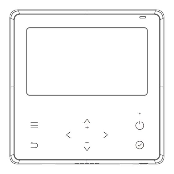
Page 13: Controller Buttons
Controller buttons ON/OFF Menu Enter Return Left / Right / Up / Down | 13... -
Page 14: Operation
Operation To start press the power button on the controller. The main page display will appear. °C °C 26.5°C 26.5°C Power-on status Power-on status main page display main page display AM , Sun, Nov 19 AM , Sun, Nov 19 Shutdown status Shutdown status main page display... - Page 15 Standby and screen off Standby occurs after 30 seconds if no button is pressed. After entering the standby state, the controller exits all setting states and restores the main page display. AM , Sun, Nov 19 °C °C Screen off occurs after 60 seconds if no button is pressed. Press any key to return to the home page screen.
- Page 16 Date and time setting The lower section of date and time setting can be set to 12/24 hour system switching, wired controller time setting or wired controller date setting. Date & Time Setting 24-Hour Time Timer Setting 09:00 Date Setting Nov-17-2021 The time, and date setting interface on the wired controller is as follows:...
- Page 17 Mode setting (M) Press the left or right buttons to select ‘Mode’. Press the up or down buttons to select the mode of operation and press the enter button (tick) to adjust the settings. If Auto or Dry mode is selected, the fan speed is fixed and cannot be adjusted—the set temperature is adjustable.
- Page 18 Fan speed setting Press the left or right buttons to select ‘Fan’. Fan speed is unavailable in ‘Auto’ or ‘Dry’ modes. Press the up or down buttons to select the fan speed and then press enter (tick) to change the fan speed. High Auto Press the up or down buttons to select customised fan speed, then...
- Page 19 Fan direction setting (model dependent) Press the left or right buttons to select louver swing. Vertical Louver Swing Horizontal Louver Swing Press the up or down buttons to select the fan direction function, press enter (tick) to enable or disable the function. When the horizontal louver swing is selected, press enter (tick) to enable/disable the horizontal swing function.
-
Page 20: Special Functions Setting
Special function settings Turbo This mode allows you to cool indoor air quickly in summer or warm it quickly in winter. In turbo mode the fan is set to operate at the maximum output. Menu > up or down buttons > function icon > enter > turbo turn on The turbo wind speed icon on the home page is displayed. - Page 21 ECO (available under cool mode only) Under cooling mode press ECO, the controller will adjust the temperature automatically to 24 °C with a fan speed of auto to save energy. Modifying the mode or adjusting the set temperature less than 24 °C will stop the ECO operation.
- Page 22 Special function setting (model dependent) This allows additional controls depending on the parameter selected. What is available will be dependent on the indoor model. Menu -> up or down buttons -> function icon -> Smart Control / Timer / or System settings -> enter or right button to enter next menu -> up or down buttons to adjust parameters ->...
- Page 23 Active Clean should be done at least twice a year, at the end of summer, and at the end of winter. This does not replace the requirement for yearly servicing of your unit. Contact you installer or Rinnai to schedule annual servicing. | 23...
- Page 24 Daily timer Daily Timer Timer On Daily Timer Timer On 09:00 : - - - Weekly timer Menu Weekly Timer Daily Timer Weekly Timer Daily Timer Use the up or down buttons to select the timer day, and use ADD to add the set time, timer on, timer off, temp, mode, and fan speed.
- Page 25 Weekly timer continued Weekly Timer Weekly Timer Weekly Timer Timer On 09:00 AM 02:00 PM Temp 26.0°C Mode Save Delete Once the first timer has been added and saved there will be a ‘Copy Timer’ option available for additional days. Weekly Timer Copy Timer Weekly Timer...
- Page 26 The delay off setting has a power-down memory function. When the delay off has been activated, when the timer function is pressed, a reminder of the delay off function will pop up. Languages English Francais Deutsch Italia Espana 26 |...
-
Page 27: Fault Codes
There are a number fault / error codes that could show on the controller. For a full list of what these are refer to the installation guide, available online at www.rinnai.co.nz. There is one error code that relates to a communication error between the wired controller and that of the indoor unit, this is EH63, this will require a service call. -
Page 28: Wi-Fi Control
• App Store Please note NetHome Plus is a third party App not run by Rinnai. For this App to run the home’s Internet router must be running on 2.4 GHz (not 5 GHz)—check the Wi-Fi settings on your device. -
Page 29: Wi-Fi Registration And Connection
As technology and App updates are frequent it has not been placed in this guide. If you are registering and connecting using the Wi-Fi App, please refer to the online user guide available on the Rinnai NZ website. Just enter ‘NetHome Plus app’ in the search field. - Page 30 Notes...
- Page 31 Notes...
- Page 32 Rinnai.co.nz Tel: 0800 746 624 http://www.youtube.com/rinnainz R32 deluxe controller op & install guide http://facebook.com.rinnainz 15130-B I 02-23...