
Related Manuals for Rinnai CNTRLDRCINW


Summary of Contents for Rinnai CNTRLDRCINW
- Page 1 MODEL CNTRLDRCINW Standard wired remote controller Operation and installation guide...
- Page 2 Must be installed, maintained and removed only by an authorised person. Warning Improper installation, adjustment, alteration, service and maintenance can cause property damage, personal injury or loss of life. For more information about buying, using, and servicing of Rinnai appliances call: 0800 RINNAI (0800 746 624).
-
Page 3: Table Of Contents
Contents Safety and important information........Installation ................Controller operation LCD display ................ Controller buttons ............... Operation ................Timer functions ..............Fault codes ................. Wi-Fi control ............... Wi-Fi registration and connection ........ -
Page 4: Safety And Important Information
Safety and important information DO NOT install the controller in a place exposed to leakage or flammable gases. Once flammable gases are leaked and left around the controller, fire may occur. DO NOT operate with wet hands or let water enter the wired controller—electric shock may occur. -
Page 5: Installation
Installation 120 mm 20 mm 46 mm 60 mm Backing plate Backing Screwdriver plate Remove the backing plate by inserting locations a flat screwdriver in the lower part of the controller, rotate (do not pry up and down) to remove the backing plate. The PCB is mounted in the upper part of the controller be careful not to damage. - Page 6 Loom access point Remove plastic knockout from the backing plate. Create a hole in the wall to access the wall cavity Remove for routing the loom from the indoor unit to the knockout controller. Put on a flat surface. Be careful not to distort the back plate of the wired controller by over tightening the mounting screws.
- Page 7 Thermostat connection to the indoor unit Loom knockout Indoor unit 60 mm Indoor unit Connect the terminals on the wired controller (HA, HB), and the terminals on the indoor unit (HA, HB). There is no polarity between HA and HB, refer image below. Indoor unit HA HB Wired controller...
- Page 8 Setting up two controllers Up to two controllers can be connected to the HA and HB terminals on the indoor unit as shown. From the factory all controllers are supplied with SW1 Controller 1 (primary) dip switch setting 1 OFF and dip switch setting 2 OFF.
- Page 9 One controller to multiple units For some units, one wired controller can support multiple units (a maximum of 16). For configuration of multiple indoor units loom connection is polarity sensitive and HA must connect to HA on all indoor units, the same applies to HB.
- Page 10 Reattach backing plate of the wired controller To reconnect the fascia to the back plate, anchor the top lugs first as shown below then swing the fascia down and press lightly to engage the bottom tabs. Be careful not to pinch the loom during the process. DO NOT allow water to enter the controller, use trap and putty to seal the connectors.
-
Page 11: Controller Operation
Controller operation Functions • Mode: Auto-Cool-Dry-Heat-Fan • Fan speed: Auto/Low/Med/High • Timer ON/OFF • Temperature setting • Weekly timer • Follow me • Turbo • Child lock • Clock... -
Page 12: Lcd Display
LCD display MODE display Temperature display Displays current mode incl. Lock display °C / °F display Room temperature Wireless control feature display (on some models) Follow me Delay off Turbo Weekly timer / ON/OFF timer Clock Filter reminder Sleep feature Fan speed Active clean Horizontal swing... -
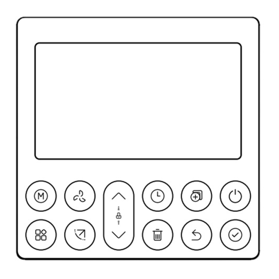
Page 13: Controller Buttons
Controller buttons Fan speed Copy Mode Power Function Confirm Swing (some models) 10. Back Adjust 11. Day off* / delay Timer * This means single day schedule deactivation. | 13... - Page 14 Setting the current day and time Press the timer button for two seconds or more. The timer display will flash. Press the down or up button to set the day. The selected day will flash. Press the timer button then press the down or up button to set the current time.
-
Page 15: Operation
Operation Turn on and off Press the power button. Selecting operation mode Press the Mode button to cycle through the different modes of operation. Adjusting room temperature setting Press the up or down button to set the room temperature. Indoor setting temperature range 16-30 °C. - Page 16 Keypad tone setting Press the swing and function buttons together for three seconds to turn on or turn off the keypad tone. Child lock function Press the up and down buttons at the same time for three seconds to activate the child lock function and lock all the buttons on the controller. Press the same two buttons again to deactivate.
- Page 17 Follow me Press the function button until the Follow me icon appears. Press confirm to activate. When Follow me is activated the room temperature is detected at the sensor in the wired controller. When Follow me is not active the room temperature is detected at the air inlet of the indoor unit.
- Page 18 Active clean should be done at least twice a year, at the end of summer, and at the end of winter. This does not replace the requirement for yearly servicing of your unit. Contact your installer or Rinnai to schedule annual servicing. 18 |...
-
Page 19: Timer Functions
Timer functions WEEKLY timer WEEK Use this timer function to set operating times for each day of the week. On timer Use this timer to start operation. The timer operates and operation starts after the time has passed. Off timer Use this timer to stop operation. - Page 20 To set the ON or OFF timer Press the timer button to select the ON day or OFF day. Press the confirm button, the timer display will blink. Press the up or down buttons to set the time. After this is done the timer will automatically start or stop.
- Page 21 Weekly timer 1 Up to four timer settings can be saved for each day of the week. Press the timer button to select the week 1. Press the confirm button. Press the up or down buttons to select the day of the week, then press confirm.
- Page 22 Weekly timer operation To activate weekly timer operation, press the timer button while ‘Week 1’ is displayed on the LCD. To deactivate weekly timer operation, press the timer button when ‘Week 1’ has disappeared from the LCD. Turning off the system during the weekly timer Press the power button once (quickly), the system will turn off temporarily but will come back on when the next timer is scheduled.
- Page 23 To set a day off During the weekly timer setting, press the confirm button. Press the up or down button to select the day in the week. Press the ‘Day off’ button to set the day off, in this example Wed. The day off can be set for other days by repeating steps 2 and 3.
- Page 24 Delay function During the weekly timer, press the function button. Select delay function and press the confirm button. The display will show “Oh” “1h” “2h”, wait three seconds to confirm. When the delay function is activated, the delay off symbol will appear. The delay function can only be enabled in Weekly Timer 1 and Weekly Timer 2.
- Page 25 The WE mark flashes quickly For example, copying the Monday setting to Wednesday. Weekly timer 2 Press the timer button to select week 2, then press confirm. Various modes such as day of the week, on timers, time setting, operation mode setting, and room temperature are set here.
- Page 26 Operation mode setting Press the up or down button to select operation mode, then press confirm. Room temperature setting Press the up or down button to set the room temperature, then press confirm. This setting is not available when in FAN or OFF modes. Fan speed setting Press the up or down button to set the fan speed, then press confirm.
- Page 27 Delete the time scale in one day When in a weekly timer setting press confirm. Press the up or down button to select the day of the week and confirm. Press the up or down button to select the setting time to be deleted. The setting time, mode and fan speed will appear on the LCD, and can be deleted by pressing the DELETE button.
-
Page 28: Fault Codes
There are a number fault / error codes that could show on the controller. For a full list of what these are refer to the installation guide, available online at www.rinnai.co.nz. There is one error code that relates to a communication error between the wired controller and that of the indoor unit, this is EH63, this will require a service call. -
Page 29: Wi-Fi Control
• App Store Please note NetHome Plus is a third party App not run by Rinnai. For this App to run the home’s Internet router must be running on 2.4 GHz (not 5 GHz)—check the Wi-Fi settings on your device. -
Page 30: Wi-Fi Registration And Connection
As technology and App updates are frequent it has not been placed in this guide. If you are registering and connecting using the Wi-Fi App, please refer to the online user guide available on the Rinnai NZ website. Just enter ‘NetHome Plus app’ in the search field. - Page 32 Rinnai.co.nz Tel: 0800 746 624 http://www.youtube.com/rinnainz R32 standard controller op & install guide http://facebook.com.rinnainz 15129-B I 02-23...