Graco President C Series Instructions-Parts List Manual
4:1 ratio pump
Hide thumbs
Also See for President C Series:
- Instructions-parts list manual (16 pages) ,
- Instructions-parts list manual (18 pages)
Table of Contents
Advertisement
Quick Links
Instructions - - Parts List
4:1 Ratio Presidentr Pump
400 psi (28 bar) Maximum Fluid Working Pressure
100 psi (7 bar) Maximum Air Input Pressure
Part No. 223183, Series C
55 Gallon (200 Liter) Drum Size, UHMWPE and Leather Packed
Part No. 223184, Series C
Stubby Size, UHMWPE and Leather Packed
Important Safety Instructions
Read all warnings and instructions in this manual.
Save these instructions.
Table of Contents
. . . . . . . . . . . . . . . . . . . . . . . . . . . . . . . . . . . . . .
. . . . . . . . . . . . . . . . . . . . . . . . . . . . . . . . . . . . .
. . . . . . . . . . . . . . . . . . . . . . . . . . . . . . . . . . . . .
. . . . . . . . . . . . . . . . . . . . . . . . . . . . . . . . . .
. . . . . . . . . . . . . . . . . . . . . . . . . . . . . . .
. . . . . . . . . . . . . . . . . . . . . . . . . . . . . . . . . . . . . .
. . . . . . . . . . . . . . . . . . . . . . . . . . . . . . . . . . . . . . . .
. . . . . . . . . . . . . . . . . . . . . . . . . . . . . . . . . . .
. . . . . . . . . . . . . . . . . . . . . . . . . . . . . . . .
GRACO INC. P.O. BOX 1441 MINNEAPOLIS, MN 55440- -1441
Copyright 1989, Graco Inc. is registered to I.S. EN ISO 9001
II 1/2 G Ex h IIB T6 Ga/Gb
ETL23ATEX0276
ITS21UKEX0322
II 2 G T6
. . . . . . . . . . . . . . . . . . . . . . . . . .
. . . . . . . . . . . . . . . . . . . . . .
. . . . . . . . . . . . . . . . . . . . . . . . . . . . .
2
5
8
11
12
13
14
16
16
17
18
18
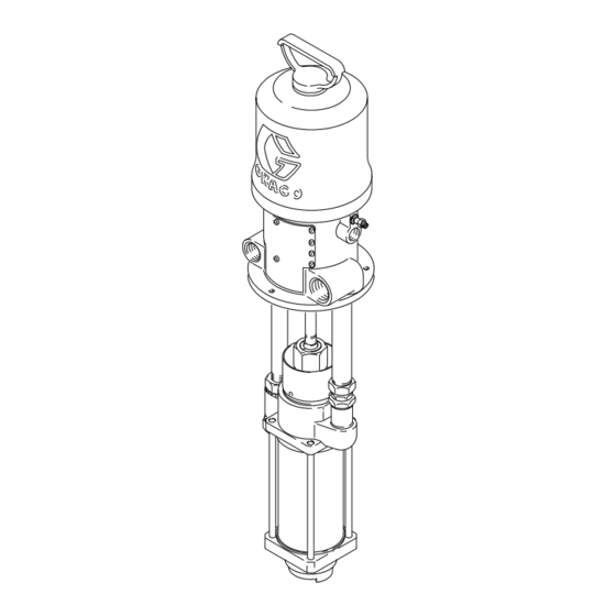
Model 223184 Shown
307986L
06107
Advertisement
Table of Contents

Related Manuals for Graco President C Series


Summary of Contents for Graco President C Series
-
Page 1: Table Of Contents
......06107 Model 223184 Shown GRACO INC. P.O. BOX 1441 MINNEAPOLIS, MN 55440- -1441 Copyright 1989, Graco Inc. is registered to I.S. EN ISO 9001... -
Page 2: Warnings
D This equipment is for professional use only. D Read all instruction manuals, tags, and labels before operating the equipment. D Use the equipment only for its intended purpose. If you are not sure, call your Graco distributor. D Do not alter or modify this equipment. - Page 3 WARNING FIRE AND EXPLOSION HAZARD Improper grounding, poor ventilation, open flames or sparks can cause a hazardous condition and result in a fire or explosion and serious injury. D Ground the equipment and the object being sprayed. Refer to Grounding on page 5. D If there is any static sparking or you feel an electric shock while using this equipment, stop spray- ing immediately.
- Page 4 Notes 307986...
-
Page 5: Installation
NOTE: Reference numbers and letters in parentheses in the text refer to the callouts in the figures and the parts drawing. NOTE: Always use Genuine Graco Parts and Acces- sories, available from your Graco distributor. If you supply your own accessories, be sure they are ade- 0864 quately sized and pressure rated for your system. - Page 6 Installation Bleed-Type Master Air Valve Fluid Shutoff Valves M Air Supply Line Main Fluid Return Line (required, for pump) G Fluid Filter Bleed-Type Master Air Valves Secondary Fluid Return Line Air Filter/Regulator Fluid Pressure Regulator (for accessories) Ground Wire (required; Air Line Lubricator Air Spray Gun Main Fluid Supply Line...
- Page 7 Installation Available Accessories (must be Fluid Line Accessories purchased separately) WARNING Air Line Accessories A fluid drain valve (D) is required in your system to WARNING help reduce the risk of serious injury, including splashing of fluid in the eyes or on the skin. A bleed-type master air valve (A) is required in your system to help reduce the risk of serious injury, The fluid drain valve assists in relieving fluid pres-...
-
Page 8: Operation
Operation Pressure Relief Procedure If the pump is not immersed, fill the packing nut/wet- cup 1/2 full with a compatible solvent. Keep the cup filled at all times to help prevent the fluid you are WARNING pumping from drying on the exposed displacement rod and damaging the throat packings. - Page 9 Operation Prime the Pump WARNING 1. See Fig. 2. Remove the spray nozzle from the To reduce the risk of serious injury whenever you gun. See the gun instruction manual. are instructed to relieve pressure, always follow the 2. Close all bleed-type air valves (A, N). Pressure Relief Procedure on page 8.
- Page 10 Notes 10 307986...
-
Page 11: Maintenance
Maintenance Shutdown and Care of the Pump CAUTION WARNING Never leave water or water-base fluid in the pump overnight. If you are pumping water-base fluid, flush with water first, then with a rust inhibitor such as To reduce the risk of serious injury whenever you mineral spirits. -
Page 12: Troubleshooting
Troubleshooting 1. Relieve the pressure. WARNING To reduce the risk of serious injury whenever you are instructed to relieve pressure, always follow the 2. Check all possible problems and solutions before Pressure Relief Procedure on page 8. disassembling pump. Problem Cause Solution Pump fails to operate. -
Page 13: Service
Service Disconnecting the Displacement Pump 6. Turn on the air to the motor and run the pump slowly. Adjust the locknuts (14) on the return NOTE: For displacement pump repair instructions, mounting tube (11) as necessary until the pump refer to the separate displacement pump manual operates smoothly at minimum air pressure to the 307983, supplied. -
Page 14: Parts
Parts Model 223183, Series C 4:1 Ratio President Pump, 55 Gallon (200 Liter) Drum Size; UHMWPE and Leather Packed Part Description 205038 AIR MOTOR, President See 306982 for parts 191733 ROD, connecting; 18.25 in. (463.6 mm) long 223177 PUMP, displacement; See 307983 for parts 100579 PIN, cotter... - Page 15 Parts Model 223184, Series C 4:1 Ratio President Pump, Stubby Size; UHMWPE and Leather Packed Part Description 205038 AIR MOTOR, President See 306982 for parts 190116 ROD, connecting; 5.69 in. (144.5 mm) long 223177 PUMP, displacement; See 307983 for parts 100579 PIN, cotter 156082...
-
Page 16: Dimensions
Dimensions Mounting Hole Layout 0.375 in. 2.254 in. (9.52 mm) (57.25 mm) diameter 2.254 in. (57.25 mm) 3.188 in. (80.97 mm) 2.625 in. (66.67 mm) 5.250 in. (133.4 mm) 3/4 npt(f) 1 in. npt(f) return outlet NOTE: Use mounting gasket 161322. 06088 Manual Change Summary... -
Page 17: Technical Data
Technical Data Category Data Ratio Maximum fluid working pressure 400 psi (28 bar) Maximum air input pressure 100 psi (7 bar) Pump cycles per 1 gallon (3.8 liters) Fluid flow at 60 cycles per minute 8 gpm (30.4 liters/min) Fluid inlet size 1--1/2 npt(f) Fluid outlet size 1 in. -
Page 18: Graco Standard Warranty
With the exception of any special, extended, or limited warranty published by Graco, Graco will, for a period of twelve months from the date of sale, repair or replace any part of the equipment determined by Graco to be defective.