Graco Dura-Flo 2400 Instructions-Parts List Manual
Stainless steel
Hide thumbs
Also See for Dura-Flo 2400:
- Instructions-parts list manual (46 pages) ,
- Instructions manual (32 pages) ,
- Instructions and parts list (10 pages)
Advertisement
Quick Links
Instructions–Parts List
STAINLESS STEEL
Dura–Flot 2400 Pumps
Severe–Duty rod and cylinder, for abrasive coatings.
Important Safety Instructions
Read all warnings and instructions in this manual.
Save these instructions.
See page 2 for Model Numbers, Maximum
Working Pressures and Table of Contents.
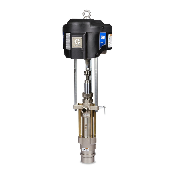
Part No. 222899 Shown
308152Z1
0566B
Advertisement

Related Manuals for Graco Dura-Flo 2400


Summary of Contents for Graco Dura-Flo 2400
- Page 1 Instructions–Parts List STAINLESS STEEL Dura–Flot 2400 Pumps 308152Z1 Severe–Duty rod and cylinder, for abrasive coatings. Important Safety Instructions Read all warnings and instructions in this manual. Save these instructions. See page 2 for Model Numbers, Maximum Working Pressures and Table of Contents. 0566B Part No.
- Page 2 ......Graco Standard Warranty ..... .
- Page 3 D This equipment is for professional use only. D Read all instruction manuals, tags, and labels before operating the equipment. D Use the equipment only for its intended purpose. If you are uncertain about usage, call your Graco distributor. D Do not alter or modify this equipment. Use only genuine Graco parts and accessories.
- Page 4 Permanently coupled hoses cannot be repaired; replace the entire hose. D Use only Graco approved hoses. Do not remove any spring guard that is used to help protect the hose from rupture caused by kinks or bends near the couplings.
- Page 5 WARNING FIRE AND EXPLOSION HAZARD Improper grounding, poor ventilation, open flames, or sparks can cause a hazardous condition and result in a fire or explosion and serious injury. D Ground the equipment and the object being sprayed. Refer to Grounding on page 7. D If there is any static sparking or you feel an electric shock while using this equipment, stop spray- ing immediately.
- Page 6 Notes 308152...
- Page 7 Part No. 184470 Fluid Outlet Fitting is available for applications requiring a smaller fluid outlet fitting than the standard 1–1/2 in. npt(m). The 184470 Fitting is 0864 3/4 npt(m) x M42 x 2.0. Contact your Graco distributor Fig. 2 to order. 308152...
- Page 8 NOTE: Always use Graco Parts and Accessories, available from your Graco distributor. If you supply your own accessories, be sure they are adequately sized and pressure rated for your system.
- Page 9 Installation (AIR-POWERED PUMPS) D A bleed-type master air valve (E) is required in System Accessories your system to relieve air trapped between it and the air motor when the valve is closed (see the WARNING WARNING at left). Be sure the bleed valve is easily accessible from the pump, and is located down- A bleed-type master air valve (E) and a fluid drain stream from the air regulator.
- Page 10 Be sure that all hydraulic fluid lines are absolutely clean. Blow out the lines with air and flush thoroughly NOTE: Accessories are available from your Graco with solvent before connecting to the hydraulic distributor. If you supply your own accessories, be sure...
- Page 11 Use a whip hose (P) and of hydraulic fluid. Use only Graco-approved hydraulic a swivel (R) between the main fluid hose (N) and the oil. Order Part No. 169236, 19 liter (5 gal.) or Part No.
- Page 12 Notes 308152...
- Page 13 (All PUMPS) Pressure Relief Procedure Packing Nut/Wet-Cup Before starting, fill the packing nut (3) 1/3 full with WARNING Graco Throat Seal Liquid (TSL) or compatible solvent. See Fig. 5. SKIN INJECTION HAZARD The system pressure must be manually WARNING relieved to prevent the system from starting or spraying accidentally.
- Page 14 Operation/Maintenance (AIR-POWERED PUMPS) Flush the Pump Before First Use CAUTION The pump is tested with lightweight oil, which is left in to protect the pump parts. If the fluid you are using Do not allow the pump to run dry. It will quickly may be contaminated by the oil, flush it out with a accelerate to a high speed, causing damage.
- Page 15 Operation/Maintenance (AIR-POWERED PUMPS) Shutdown and Care of the Pump WARNING WARNING To reduce the risk of serious injury whenever you are instructed to relieve pressure, always follow the To reduce the risk of serious injury whenever you Pressure Relief Procedure on page 13. are instructed to relieve pressure, always follow the Pressure Relief Procedure on page 13.
- Page 16 Operation/Maintenance (HYDRAULIC-POWERED PUMPS) Flush the Pump Before First Use CAUTION The pump is tested with lightweight oil, which is left in Do not allow the pump to run dry. It will quickly to protect the pump parts. If the fluid you are using accelerate to a high speed, causing damage.
- Page 17 Operation/Maintenance (HYDRAULIC-POWERED PUMPS) Shutdown and Care of the Pump WARNING WARNING To reduce the risk of serious injury whenever you are instructed to relieve pressure, always follow the To reduce the risk of serious injury whenever you Pressure Relief Procedure on page 13. are instructed to relieve pressure, always follow the Pressure Relief Procedure on page 13.
- Page 18 Turn on the air/hydraulic power just enough to start the pump. If the pump starts when the air/hydraulic power is turned on, the obstruction is in the fluid hose or gun. NOTE: If you experience air motor icing, call your Graco Distributor. 308152...
- Page 19 Service Required Tools CAUTION D Set of socket wrenches D Set of adjustable wrenches Be sure to use at least two people when lifting, mov- D 24 in. adjustable wrench ing, or disconnecting the pump. This pump is too D Torque wrench heavy for one person.
- Page 20 Fill the wet-cup (3) 1/3 full of torque is necessary to prevent the rod adapter from Graco Throat Seal Liquid or compatible solvent. loosening during the pump operation. 6. Turn on the air or hydraulic power supply. On...
- Page 21 Service Premier Pumps King, Bulldog, and Viscount Pumps (Model 222943 shown) (Model 222899 shown) 0567B 01397C Torque to 196–210 NSm (145–155 ft-lb) Square hole is for use with torque wrench. Torque to 129–142 NSm (95–105 ft-lb) Torque to 128–156 NSm (95–115 ft-lb). Torque to 312–340 NSm (230–250 ft-lb) Torque to 81–89 NSm (60–66 ft-lb) Apply LoctiteR 2760t (or equivalent) to threads.
- Page 22 Service Displacement Pump Service CAUTION Disassembly When disassembling the pump, lay out all the removed To reduce the possibility of costly damage to the rod parts in sequence, to ease reassembly. Clean all parts (1) and cylinder (7), always use a rubber mallet or an with a compatible solvent and inspect them for wear or arbor press to drive the rod out of the cylinder.
- Page 23 Service Included only on Displacement Pumps 222803, 222994, and 241648 with stainless steel cap screws (20). Fig. 7 0421A 308152...
- Page 24 Service Reassembly 7. Lubricate the throat packings (T). Place the male gland (28*) into the outlet housing (19). Install the 1. If it was necessary to remove the ball guide (9) five v-packings one at a time with the lips facing from the displacement rod (1), place the flats of down.
- Page 25 Service Torque to 141–185 NSm (104–136 ft-lb) Torque to 60–70 NSm (45–55 ft-lbs). For displacement pump 241648 only, limit packing nut torque to 27–40 NSm (20–30 ft-lb). Torque to 444–492 NSm (327–363 ft-lb) Torque oppositely and evenly to 217–299 NSm (160–220 ft-lb) Apply anti-seize lubricant to threads and mating faces Lubricate Apply thread lubricant...
- Page 26 Parts Part No. 222827 Pump, Series A 10:1 Ratio, with Bulldog Air Motor Ref. Part No. Description Qty. 208356 AIR MOTOR, Bulldog See manual 307049 for parts 102{ 184451 ADAPTER, connecting rod 103{ 184096 NUT, coupling 184278 WRENCH, packing nut 222803 PUMP, displacement See pages 30 &...
- Page 27 Parts Part No. 222899 Pump, Series B Part No. 222898 Pump, Series B 20:1 Ratio, with King Air Motor 20:1 Ratio, with Quiet King Air Motor † † † † † † † † † † 0567B 0568B Ref. Ref. Part No.
- Page 28 Parts Part No. 222943 Pump, Series B Ref. Part No. Description Qty. 34:1 Ratio, with Premier Air Motor 222800 AIR MOTOR, Premier Part No. 249157 Pump, Series A See manual 308213 for parts 34:1 Ratio, with Premier Air Motor 102{ 184582 ADAPTER, connecting rod 103{...
- Page 29 Parts Part No. 222900 Pump, Series B Ref. Part No. Description Qty. with Viscount Hydraulic Motor 235345 HYDRAULIC MOTOR, Viscount See manual 307158 for parts 102{ 184595 ADAPTER, connecting rod 103{ 184096 NUT, coupling 184278 WRENCH, packing nut 222803 PUMP, displacement See pages 30 &...
- Page 30 Displacement Pump Parts NOTE: The parts listed on this page are common to all displacement pumps covered in this manual. The pumps use different packing configurations. Pump Models 222803, 222994, 241648, 15F298 and 249991 use stainless steel cap screws with washers. Models 222993, 236226, and 236230 use carbon steel cap screws without a washer.
- Page 31 Displacement Pump Parts Part Part Description Description 184002 ROD, displacement; stainless steel 184282 GUIDE, ball, intake; stainless steel 15G854 ROD, displacement; stainless steel 222838 HOUSING, seat, intake valve; (used on 249991 only) stainless steel w/tungsten carbide seat 1 184388 PACKING NUT/WET-CUP; 253742 HOUSING, valve, seat stainless steel...
- Page 32 Displacement Pump Parts Standard Displacement Pumps Displacement Pump 222803, Series A (UHMWPE and PTFE Packings, with Stainless Steel Cap Screws) THROAT PACKINGS: PISTON PACKINGS: Part LIPS FACE DOWN LIPS FACE UP Description 109266 V-PACKING; piston; UHMWPE 184236 GLAND, male; piston; stainless steel 109316 V-PACKING;...
- Page 33 Displacement Pump Parts Standard Displacement Pumps Displacement Pump 249991, Series A, (UHMWPE Submicron and Leather Packings) NOTE: For this pump only limit packing nut torques to 27–40 THROAT PACKINGS: PISTON PACKINGS: NSm (20–30 ft–lb). LIPS FACE DOWN LIPS FACE UP Part Description 109266...
- Page 34 Displacement Pump Parts Optional Displacement Pumps Displacement Pump 236226, Series A (UHMWPE and PTFE Packings, with Carbon Steel Cap Screws) THROAT PACKINGS: PISTON PACKINGS: LIPS FACE DOWN LIPS FACE UP Part Description 109266 V-PACKING; piston; UHMWPE 184236 GLAND, male; piston; stainless steel 109316 V-PACKING;...
- Page 35 Displacement Pump Parts Optional Displacement Pumps Displacement Pump 236230, Series A, (Leather Packings and PTFE Backup, with Carbon Steel Cap Screws) THROAT PACKINGS: PISTON PACKINGS: LIPS FACE DOWN LIPS FACE UP Part Description 184236 GLAND, male; piston; stainless steel 109316 V-PACKING;...
- Page 36 Technical Data (Bulldog Pumps) WARNING Be sure that all fluids and solvents used are chemically compatible with the Wetted Parts listed below. Always read the manufacturer’s literature before using fluid or solvent in this pump. Category Data Ratio 10:1 Maximum fluid working pressure 7.0 MPa, 70 bar (1000 psi) Maximum air input pressure 0.7 MPa, 7 bar (100 psi)
- Page 37 Technical Data (Bulldog Pumps) Performance Charts: Standard Bulldog Pumps To find Fluid Outlet Pressure (psi/MPa/bar) at a specific fluid flow To find Pump Air Consumption (m#/min or scfm) at a specific fluid (lpm/gpm) and operating air pressure (psi/MPa/bar): flow (lpm/gpm) and air pressure (psi/MPa/bar): 1.
- Page 38 Technical Data (King Pumps) WARNING Be sure that all fluids and solvents used are chemically compatible with the Wetted Parts listed below. Always read the manufacturer’s literature before using fluid or solvent in this pump. Category Data Ratio 20:1 Maximum fluid working pressure 13.8 MPa, 138 bar (2000 psi) Maximum air input pressure 0.7 MPa, 7 bar (100 psi)
- Page 39 Technical Data (King Pumps) Performance Charts: Standard King Pumps To find Fluid Outlet Pressure (psi/MPa/bar) at a specific fluid flow To find Pump Air Consumption (m#/min or scfm) at a specific fluid (lpm/gpm) and operating air pressure (psi/MPa/bar): flow (lpm/gpm) and air pressure (psi/MPa/bar): 1.
- Page 40 Technical Data (Premier Pump) WARNING Be sure that all fluids and solvents used are chemically compatible with the Wetted Parts listed below. Always read the manufacturer’s literature before using fluid or solvent in this pump. Category Data Ratio 34:1 Maximum fluid working pressure 23.0 MPa, 234 bar (3400 psi) Maximum air input pressure 0.7 MPa, 7 bar (100 psi)
- Page 41 Technical Data (Premier Pump) Performance Charts: Premier Pumps To find Fluid Outlet Pressure (psi/MPa/bar) at a specific fluid flow To find Pump Air Consumption (m#/min or scfm) at a specific fluid (lpm/gpm) and operating air pressure (psi/MPa/bar): flow (lpm/gpm) and air pressure (psi/MPa/bar): 1.
- Page 42 Technical Data (Viscount Pump) WARNING Be sure that all fluids and solvents used are chemically compatible with the Wetted Parts listed below. Always read the manufacturer’s literature before using fluid or solvent in this pump. Category Data Maximum fluid working pressure 14.0 MPa, 138 bar (2000 psi) Maximum oil input pressure 10.0 MPa, 103 bar (1500 psi)
- Page 43 Technical Data (Viscount Pump) Performance Charts: Viscount Pump To find Fluid Outlet Pressure (psi/MPa/bar) at a specific fluid flow To find Pump Hydraulic Oil Consumption (m#/min or scfm) at a (lpm/gpm) and operating hydraulic pressure (psi/MPa/bar): specific fluid flow (lpm/gpm) and hydraulic pressure (psi/MPa/bar): 1.
- Page 44 Dimensions Model 222899 Shown 0566B Pump Model 222827 1183 mm (46.58 in.) 642.6 mm (25.3 in.) 540.5 mm (21.28 in.) 298.0 mm (11.73 in.) 222899 1226 mm (48.25 in.) 642.6 mm (25.3 in.) 583.0 mm (22.95 in.) 298.0 mm (11.73 in.) 222898 1235 mm (48.63 in.) 642.6 mm (25.3 in.)
- Page 45 Mounting Hole Layouts King, Bulldog, and Viscount Pumps 94.28 mm (3.712 in.) 101.6 mm 94.28 mm (4.0 in.) (3.712 in.) 50.8 mm (2.0 in.) 11.1 mm (0.437 in.) DIA (4) 88 mm (3.464 in.) 0653 Premier Pumps 135.0 mm 67.5 mm (5.3 in.) (2.7 in.) 116.9 mm...
- Page 46 With the exception of any special, extended, or limited warranty published by Graco, Graco will, for a period of twelve months from the date of sale, repair or replace any part of the equipment determined by Graco to be defective.