Graco President A Series Instructions-Parts List Manual
3:1 ratio heated circulation package
Hide thumbs
Also See for President A Series:
- Instructions-parts list manual (16 pages) ,
- Instructions-parts list manual (18 pages)
Advertisement
Quick Links
Instructions – Parts List
Parts
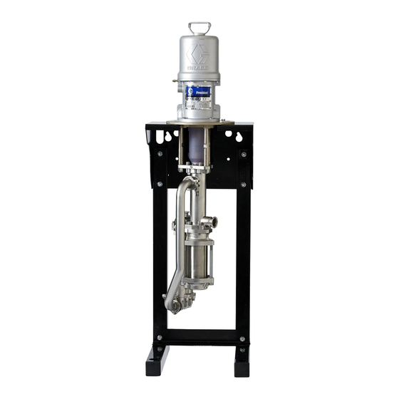
3:1 Ratio President
Circulation Package
Part No. 232090, Series A
With stainless steel pump, 239857 Supply Module, and 120V Viscon HP Heater
Package includes mounting hardware, air controls, back pressure regulator,
stainless steel fluid filter, elevator, back-geared agitator, and drum cover
300 psi (2.1 MPa, 21 bar)
Maximum Working Pressure
100 psi (0.7 MPa, 7 bar)
Maximum Air Inlet Pressure
Read warnings and instructions.
See page 2 for Table of Contents.
GRACO INC. P.O. BOX 1441 MINNEAPOLIS, MN 55440-1441
Copyright 1997, Graco Inc. is registered to I.S. EN ISO 9001
R
Heated
308770F
7759C
Advertisement

Related Manuals for Graco President A Series


Summary of Contents for Graco President A Series
- Page 1 100 psi (0.7 MPa, 7 bar) Maximum Air Inlet Pressure Read warnings and instructions. See page 2 for Table of Contents. 7759C GRACO INC. P.O. BOX 1441 MINNEAPOLIS, MN 55440-1441 Copyright 1997, Graco Inc. is registered to I.S. EN ISO 9001...
- Page 2 D This equipment is for professional use only. D Read all instruction manuals, tags, and labels before operating the equipment. D Use the equipment only for its intended purpose. If you are uncertain about usage, call your Graco distributor. D Do not alter or modify this equipment. Use only genuine Graco parts and accessories.
- Page 3 WARNING PRESSURIZED EQUIPMENT HAZARD Spray from the gun, hose leaks, or ruptured components can splash fluid in the eyes or on the skin and cause serious injury. D Do not point the gun at anyone or at any part of the body. D Do not stop or deflect leaks with your hand, body, glove, or rag.
- Page 4 WARNING FIRE, EXPLOSION, AND ELECTRIC SHOCK HAZARD Improper grounding, poor ventilation, open flames, or sparks can cause a hazardous condition and result in a fire or explosion and serious injury. D The electric heater must be installed, operated, and serviced only by trained, qualified personnel who fully understand the requirements stated in the heater instruction manual (supplied).
- Page 5 Ensure that the wall is strong enough to support the NOTE: Always use Genuine Graco Parts and Acces- weight of the pump and accessories, heater, fluid, sories, available from your Graco distributor. Refer to hoses, and stress caused during pump operation.
- Page 6 Installation D The air line lubricator (11b) provides automatic Supplied Components lubrication of the air motor. Refer to Fig. 1. D The air relief valve (11j) opens automatically to WARNING prevent overpressurization of the pump. A red-handled bleed-type master air valve (11h) and a fluid drain valve (208) are supplied.
- Page 7 Installation Detail of Air Controls Ensure that there is 9 ft (2.8 m) overhead clearance for the elevator when fully raised. Mount the pump module so the top of the bracket is 4 to 5 ft (1.2 to 1.5 m) above the floor. The suction hose is 6 ft (1.8 m) long.
- Page 8 Installation Installing the Pump Module 4. Using two people, hang the pump module on the bracket mounting plate (37). Have one person hold The pump module consists of the pump mounted on the module in place while the other checks that the the pump bracket, the air controls, back pressure pump bracket (22) is level.
- Page 9 Installation Installing the 239857 Supply Module Using the Quick Connectors NOTE: Refer to Fig. 1 on page 7, and to the Dimen- To open a quick connector (11c), loosen the captive sion drawing on page 26 and the Mounting Hole Lay- screw (S) and open the connector.
- Page 10 Installation Fluid Heater WARNING The fluid heater (201) heats the fluid as it passes through, to maintain the correct spraying viscosity. COMPONENT RUPTURE HAZARD Heat causes fluid to expand. If the Read and understand all instructions in the supplied heated fluid is trapped with nowhere to heater manual (309524) before operating the heater.
- Page 11 Installation Installing the Heater Module 4. Bolt the bracket (205) to the wall with 1/2 in. bolts and washers. Use bolts that are long enough to NOTE: Refer to Fig. 3, and to the Dimension drawing keep the bracket from vibrating during operation. on page 26 and the Mounting Hole Layouts on page 5.
- Page 12 Notes 308770...
- Page 13 Installation Grounding 4. Viscon HP Heater: refer to the heater manual, supplied. WARNING 5. Spray gun: ground through connection to a prop- erly grounded fluid hose and pump. FIRE, EXPLOSION, AND ELECTRIC SHOCK HAZARD 6. Agitator: use the ground wire and clamp (108, Before operating the pump, ground the supplied).
- Page 14 Packing Nut Before starting, fill the packing nut (H) 1/3 full with HOT SURFACE HAZARD Graco Throat Seal Liquid (TSL) or compatible solvent. Do not touch the heater while it is oper- See Fig. 6. ating. Allow the heater to cool for at least...
- Page 15 Operation Prime the Pump Adjust the Spray Pattern 1. Disconnect the electric power to the heater before priming the pump. 1. Start the pump. Connect the electric power to the heater. Turn the 3-way recirculation valve (19) to 2. Open the fluid shutoff valve (14). the circulation position.
- Page 16 Operation Elevator Operation 3. Slowly open the needle valve (L) to start the agitator (102). Use the valve to adjust the speed. 1. To raise the elevator (150), connect the quick Do not operate the agitator too fast. If the fluid coupler (124) on the end of the coiled hose (105) foams or a vortex forms on the fluid surface, to the male fitting (J) on the air control valve (K).
- Page 17 Operation Torque packing nut (H) to 34–40 NSm (25–30 ft-lb). Packing nut is partially hidden. 12, 14 Items 12 and 14 are partially hidden. 7759C Fig. 6 308770...
- Page 18 Maintenance Preventive Maintenance Schedule 5. Lower the agitator (102) into a container of solvent. Start the agitator and run it slowly. The operating conditions of your particular system determine how often maintenance is required. Estab- 6. Hold a metal part of the gun firmly to the side of a lish a preventive maintenance schedule by recording grounded metal pail.
- Page 19 Maintenance Repair Kit 239383 (includes items 301 to Model 113765 307). For Part No. 113765 Air Air Filter/Regulator Shown Filter/Regulator. Kit parts are marked with an asterisk (301*). Individual Lubricate with no. 2 parts are not available separately. lithium-base grease. Ref.
- Page 20 Parts Pump Module Parts 21 (Ref) 10 (Ref) 21 41 7756B 308770...
- Page 21 Parts Pump Module Parts Ref. Ref. Part No. Description Qty. Part No. Description Qty. 239854 PUMP, President; 3:1 ratio; stainless steel; see manual 308793 221171 HOSE, suction, with ground wire; 503086 NIPPLE, reducing; stainless steel; 1 in. 1 nylon; 3/4 npt(mbe) stainless steel x 1/2 npt couplings;...
- Page 22 Parts Supply Module Parts Pump Module. See page 20 for parts. 159 (Ref) 105 (Ref) 155 (Ref) 102 (Ref) 109 (Ref) 7757B 308770...
- Page 23 Parts Supply Module Parts Ref. Ref. Part No. Description Qty. Part No. Description Qty. 112268 SWIVEL; stainless steel; 3/4 npt (m x f) 1 238157 AGITATOR, back-geared; 238283 COVER, drum; stainless steel; see manual 308609 see manual 308466 502851 BUSHING; sst; 1 in. npt(m) x 3/4 npt(f) 1 208536 COUPLER, quick disconnect, female 500251...
- Page 24 Parts Part No. 232090, Series A, 3:1 President heated circulation package Pump Module. See page 20 for parts. Supply Module. See page 22 for parts. 201 (Ref) 7758D Ref. Ref. Part No. Description Qty. Part No. Description Qty. 237529 VALVE, ball; stainless steel; 1/4 npt 245848 HEATER, fluid, 120V;...
- Page 25 Technical Data Part No. 232090, Series A, 3:1 President heated circulation package Category Data Maximum fluid working pressure 300 psi (2.1 MPa, 21 bar) Maximum air input pressure 100 psi (0.7 MPa, 7 bar) Ratio Maximum heater voltage and 120 VAC, 19.2 Ampere amperage Maximum operating temperature 150_F (66_C)
- Page 26 Dimensions Ensure that there is 9 ft (2.8 m) overhead clearance for the elevator when fully raised. Mount the pump module so the top of the bracket is 4 to 5 ft (1.2 to 1.5 m) above the floor. The suction hose is 6 ft (1.8 m) long. Do not stretch the hose tight;...
- Page 27 Mounting Hole Layouts Check that the bracket is level before bolting it to the wall. Mount the bracket so the top edge is 4 to 5 ft (1.2 to 1.5 m) above the floor. Slots must face up.. Pump Wall Bracket Mounting Diagram Heater Wall Bracket Mounting Diagram 9 in.
- Page 28 Graco distributor to the original purchaser for use. With the exception of any special, extended, or limited warranty published by Graco, Graco will, for a period of twelve months from the date of sale, repair or replace any part of the equipment determined by Graco to be defective.