
Related Manuals for Dell OptiPlex 7050 Tower


Summary of Contents for Dell OptiPlex 7050 Tower
- Page 1 OptiPlex 7050 Tower Owner's Manual Regulatory Model: D18M Regulatory Type: D18M003...
- Page 2 A WARNING indicates a potential for property damage, personal injury, or death. © 2017 Dell Inc. or its subsidiaries. All rights reserved. Dell, EMC, and other trademarks are trademarks of Dell Inc. or its subsidiaries. Other trademarks may be trademarks of their respective owners.
-
Page 3: Table Of Contents
Contents 1 Working on your computer..........................7 Safety instructions................................7 Before working inside your computer..........................7 Turning off your computer..............................8 Turning off your computer — Windows 10.......................8 Turning off your computer — Windows 7.........................8 After working inside your computer..........................8 2 Removing and installing components...................... - Page 4 Installing power supply unit (PSU)...........................27 VGA daughter board................................28 Removing VGA daughter board..........................28 Installing VGA daughter board..........................29 Intrusion switch................................29 Removing intrusion switch............................29 Installing intrusion switch............................30 Power switch..................................30 Removing power switch............................30 Installing power switch.............................. 32 Speaker..................................... 32 Removing speaker..............................32 Installing speaker................................
- Page 5 Downloading the audio driver...........................68 7 Troubleshooting your computer........................69 Diagnostic power LED codes............................69 Power LED issue................................70 Dell Enhanced Pre-Boot System Assessment (ePSA) diagnostic 3.0............... 70 Running the ePSA diagnostics..........................70 Diagnostic error messages...............................71 System error messages..............................74 Verifying system memory in Windows 10 and Windows 7 ..................74 Windows 10.................................
- Page 6 System board layout................................ 79 Controls and lights specifications..........................80 Environmental specifications............................80 9 Contacting Dell............................82 Contents...
-
Page 7: Working On Your Computer
Damage due to servicing that is not authorized by Dell is not covered by your warranty. Read and follow the safety instructions that came with the product. -
Page 8: Turning Off Your Computer
Turning off your computer Turning off your computer — Windows 10 CAUTION: To avoid losing data, save and close all open files and exit all open programs before you turn off your computer. Click or tap Click or tap and then click or tap Shut down. NOTE: Ensure that the computer and all attached devices are turned off. -
Page 9: Removing And Installing Components
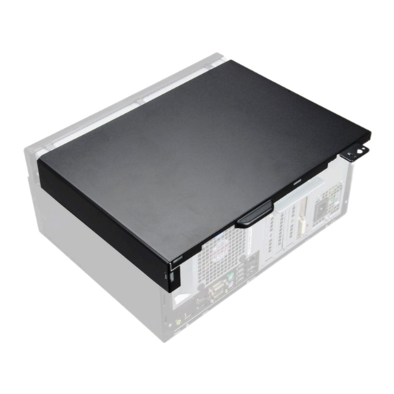
Removing and installing components This section provides detailed information on how to remove or install the components from your computer. Recommended tools The procedures in this document require the following tools: • Small flat blade screwdriver • Phillips # 1 screwdriver •... - Page 10 Lift the cover to remove it from the computer. Removing and installing components...
-
Page 11: Installing Cover
Installing cover Place the cover on the computer and slide the cover forward until it clicks into place. Follow the procedure in After working inside your computer. Front Bezel Removing bezel Follow the procedure in Before working inside your computer. Remove the cover. -
Page 12: Installing Bezel
Installing bezel Position the bezel to align the tab holders on the chassis. Press the bezel until the tabs click into place. Install the cover. Follow the procedure in After working inside your computer. Opening the front panel door Follow the procedure in Before working inside your computer. -
Page 13: Storage
Storage Removing 3.5–inch hard drive assembly Follow the procedure in Before working inside your computer. Remove the: cover bezel To remove the hard drive assembly: Disconnect the hard drive assembly cables from the connectors on the hard drive. Removing and installing components... - Page 14 b Press the blue tab [1] and pull the hard drive assembly out of the computer [ 2]. Removing and installing components...
-
Page 15: Removing 3.5-Inch Hard Drive From The Hard Drive Bracket
Removing 3.5–inch hard drive from the hard drive bracket Follow the procedure in Before working inside your computer. Remove the: cover bezel hard drive assembly To remove the hard drive bracket: Pull one side of the hard drive bracket to disengage the pins on the bracket from the slots on the hard drive [1]. b Lift the hard drive out of the hard drive bracket [2]. -
Page 16: Installing The 3.5-Inch Hard Drive Into The Hard Drive Bracket
Installing the 3.5–inch hard drive into the hard drive bracket Flex the other side of the hard drive bracket, and align and insert the pins on the bracket into the hard drive. Insert the hard drive into the hard drive bracket until it clicks into place. Install the: hard drive assembly bezel... -
Page 17: Removing The 2.5-Inch Drive From The Drive Bracket
Removing the 2.5–inch drive from the drive bracket Follow the procedure in Before Working Inside Your Computer. Remove the: cover bezel 2.5–inch drive assembly To remove the drive: Pull one side of the drive bracket to disengage the pins on the bracket from the slots on the drive [1]. b Lift the drive out of the drive bracket [2]. -
Page 18: Installing The 2.5-Inch Hard Drive Into The Hard Drive Bracket
Installing the 2.5–inch hard drive into the hard drive bracket Flex the other side of the hard drive bracket, and align and insert the pins on the bracket into the hard drive. Insert the hard drive into the hard drive bracket until it clicks into place. Install the: hard drive assembly bezel... - Page 19 Press the blue release tab [1] and slide the optical drive out of the computer [2]. Removing and installing components...
-
Page 20: Installing Optical Drive
Installing optical drive Insert the optical drive into the optical drive bay until it clicks into place. Open the front panel door. Route the data cable and power cable under the drive cage. Connect the data cable and power cable to the connectors on the optical drive. Close the front panel door. -
Page 21: Installing Optional M.2 Pcie Ssd
Open the front panel door. To remove the M.2 PCIe SSD: Pull the blue tab that secures the M.2 PCIe SSD to the system board [1]. b Disconnect the M.2 PCIe SSD from the connector on the system board [2]. Installing optional M.2 PCIe SSD Insert the M.2 PCIe SSD to the connector. -
Page 22: Sd Card Reader
SD card reader Removing SD card reader Follow the procedure in Before working inside your computer. Remove the: cover bezel Open the front panel door. To remove the SD card reader: Disconnect the SD card reader cable from the connector on the system board [1]. b Remove the screw that secures the SD card reader to the front panel door [2]. -
Page 23: Installing Sd Card Reader
Installing SD card reader Insert the SD card reader into the slot on the front panel door. Tighten the screw to secure the SD card reader to the front panel door. Connect the SD card reader cable to the connector on the system board. Close the front panel door. -
Page 24: Expansion Card
Expansion card Removing PCIe expansion card Follow the procedure in Before working inside your computer. Remove the: cover bezel Open the front panel door. To remove the PCIe expansion card: Pull the release latch to unlock the PCIe expansion card [1]. b Push the card retention latch [2], and lift the PCIe expansion card out of the computer [3]. -
Page 25: Installing Pcie Expansion Card
Installing PCIe expansion card Pull the release latch backward to open [1]. To remove the PCIe brackets (1 and 3) as shown below, insert a screwdriver in the hole of a PCIe bracket and push hard to release the bracket [2], and then lift the bracket out from your computer. NOTE: To remove the PCIe brackets (2 and 4), push the bracket upwards from the inside of your computer to release it and then lift the bracket away from your computer. -
Page 26: Power Supply Unit
Follow the procedure in After working inside your computer. Power supply unit Removing power supply unit (PSU) Follow the procedure in Before working inside your computer. Remove the: cover bezel Open the front panel door. To release the PSU: Disconnect the PSU cables from the connectors on the system board [1] [2]. b Pull the release clip [3]. -
Page 27: Installing Power Supply Unit (Psu)
Installing power supply unit (PSU) Insert the PSU into the PSU slot and slide it toward the back of the computer until it clicks into place. Tighten the screws to secure the PSU to the computer. Route the PSU cables through the retention clips. Connect the PSU cables to the connectors on the system board. -
Page 28: Vga Daughter Board
VGA daughter board Removing VGA daughter board Follow the procedure in Before working inside your computer. Remove the: cover bezel Open the front panel door To remove the VGA daughter board: Remove the screws that secure the VGA connector to the computer [1]. b Slide the VGA connector to release it from the computer. -
Page 29: Installing Vga Daughter Board
Installing VGA daughter board Align the VGA daughter board with the screw holder on the system board. Tighten the screw to secure the VGA daughter board to the system board. Insert the VGA connector into the slot at the back of the computer. Tighten the screws to secure the VGA connector to the computer. -
Page 30: Installing Intrusion Switch
Installing intrusion switch Insert the intrusion switch into the slot on the computer. Route the intrusion switch cable through the fan grommet. Connect the intrusion switch cable to the connector on the system board. Close the front panel door. Install the: bezel cover Follow the procedure in... - Page 31 cover bezel Open the front panel door. To release the power switch: Disconnect the power switch cable from the system board [1]. b Unroute the power switch cable through the retention clip [2]. Press the release tabs using a plastic scribe and slide the power switch out from the front of the computer [3]. d Close the front panel door [4].
-
Page 32: Installing Power Switch
Installing power switch Insert the power switch into the slot from the front of the computer and press it until it clicks into place. Route the power switch cable through the retention clip. Align the cable with the pins on the connector and connect the cable. Close the front panel door. - Page 33 Open the front panel door. To remove the speaker: Disconnect the speaker cable from the connector on the system board [1]. b Close the front panel door. Press the release tabs [1], and slide the speaker [2] out of the slot. Removing and installing components...
-
Page 34: Installing Speaker
Installing speaker Insert the speaker into the slot and press it until it clicks into place. Connect the speaker cable to the connector on the system board. Close the front panel door. Install the: bezel cover Follow the procedure in After working inside your computer. -
Page 35: Installing The Coin Cell Battery
To remove the coin cell battery: Press the release latch until the coin cell battery pops out [1]. b Remove the coin cell battery from the connector on the system board [2]. Installing the coin cell battery Hold the coin cell battery with the "+" sign facing up and slide it under the securing tabs at the positive side of the connector. Press the battery into the connector until it locks into place. -
Page 36: Heat Sink Assembly
Heat sink assembly Removing heat sink assembly Follow the procedure in Before working inside your computer. Remove the: cover bezel Open the front panel door. To remove the heat sink assembly: Disconnect the heat sink assembly cable from the connector on the system board [1]. b Loosen the captive screws that secure the heat sink assembly to the system board [2]. -
Page 37: Installing Heat Sink Assembly
Installing heat sink assembly Align the screws of the heat sink assembly with the holders on the system board. Place the heat sink assembly on the processor. Tighten the captive screws to secure the heat sink assembly to the system board. Connect the heat sink assembly cable to the connector on the system board. -
Page 38: Installing Processor
Installing processor Align the processor with the socket keys. CAUTION: Do not use force to seat the processor. When the processor is positioned correctly, it engages easily into the socket. Align the pin-1 indicator of the processor with the triangle on the socket. Place the processor on the socket such that the slots on the processor align with the socket keys. -
Page 39: System Fan
System fan Removing system fan Follow the procedure in Before working inside your computer. Remove the: cover bezel intrusion switch Open the front panel door. To remove the system fan: Disconnect the system fan cable from the connector on the system board [1]. b Remove the tape that holds the intrusion switch cable on the system fan and move the cable away. -
Page 40: Installing System Fan
Installing system fan Insert the grommets into the slots on the back of the computer. Hold the system fan with the cable facing the bottom of the computer. Align the grooves of the system fan with the grommets on the chassis wall. Pass the grommets through the corresponding grooves on the system fan. - Page 41 Disconnect the following cables from the system board: PSU [1] b power switch [2] speaker [3] d PSU [4] power distribution for optical drive and hard drive [5] system fan [6] g intrusion switch [7] Removing and installing components...
- Page 42 To remove the system board: Remove the screws that secure the system board to the computer [1]. b Slide and lift the system board away from the computer [2]. Removing and installing components...
-
Page 43: Installing The System Board
Installing the system board Hold the system board by its edges and align it toward the back of the computer. Lower the system board into the computer until the connectors at the back of the system board align with the slots on the chassis, and the screw holes on the system board align with the standoffs on the computer. - Page 44 memory module optional M.2 PCIe SSD expansion card SD card reader processor heat sink assembly VGA daughter board Close the front panel door. Install the: bezel cover Follow the procedure in After working inside your computer. Removing and installing components...
-
Page 45: M.2 Intel Optane Memory Module 16 Gb
M.2 Intel Optane Memory Module 16 GB Overview This document describes the specifications and capabilities of the Intel® Optane memory module. The Intel® Optane memory is a system acceleration solution developed for 7th Generation Intel® Core processor-based platforms. The Intel® Optane memory module is architected with the high performance controller interface Non-Volatile Memory Express (NVMe*)- delivering outstanding performance, low latency and quality of service. - Page 46 b Place the thermal pad on the SSD slot and remove the white adhesive tape. Place the M.2 Intel optane memory module into the slot on the thermal pad. M.2 Intel Optane Memory Module 16 GB...
-
Page 47: Product Specifications
d If the system is shipped with screw tighten that secures the M.2 Intel optane memory module on the computer. If the system is shipped with self locking spacer press to lock the M.2 Intel optane to secure on the computer. Product specifications Features Specification... -
Page 48: Environmental Conditions
Supported Platforms 7th generation or newer Intel Core processor based platforms Power • 3.3V Supply Rail • Active: 3.5 W • Drive Idel :900mW to 1.2W Compliance • NVMe Express 1.1 • PCI Express Base specifiation rev 3.0 • PCI M.2 HS Spec Certification and Declarationsµ... -
Page 49: Troubleshooting
Operating 1500 G / 0.5 ms Non-operating 230 G / 3 msec Vibration 2.17 G (5–800Hz) Max Operating 3.13 G (5–800Hz) Max Non-operating NOTES: Operating temperature is targeted for 70º C. Please contact your Intel representative for details on the non-operating temperature range. Temperature gradient measured without condensation. -
Page 50: Technology And Components
Technology and components USB features The Universal Serial Bus, or well known as USB was introduced to the PC world in 1996 which dramatically simplified the connection between host computer and peripheral devices such as mice and keyboards, external hard drive or optical devices, Bluetooth and many more peripheral devices in the market. -
Page 51: Applications
commonly known as USB 2.0 and 1.1 respectively, the slower modes still operate at 480Mbps and 12Mbps respectively and are kept to maintain backward compatibility. USB 3.0/USB 3.1 Gen 1 achieves the much higher performance by the technical changes below: •... -
Page 52: Compatibility
Compatibility The good news is that USB 3.0/USB 3.1 Gen 1 has been carefully planned from the start to peacefully co-exist with USB 2.0. First of all, while USB 3.0/USB 3.1 Gen 1 specifies new physical connections and thus new cables to take advantage of the higher speed capability of the new protocol, the connector itself remains the same rectangular shape with the four USB 2.0 contacts in the exact same location as before. - Page 53 • Audio HDMI supports multiple audio formats from standard stereo to multichannel surround sound • HDMI combines video and multichannel audio into a single cable, eliminating the cost, complexity, and confusion of multiple cables currently used in A/V systems • HDMI supports communication between the video source (such as a DVD player) and the DTV, enabling new functionality Technology and components...
-
Page 54: System Setup
Boot Sequence allows you to bypass the System Setup–defined boot device order and boot directly to a specific device (for example: optical drive or hard drive). During the Power-on Self Test (POST), when the Dell logo appears. you can: •... -
Page 55: System And Setup Password
Table 4. Navigation Keys Keys Navigation Up arrow Moves to the previous field. Down arrow Moves to the next field. <Enter> Allows you to select a value in the selected field (if applicable) or follow the link in the field. Spacebar Expands or collapses a drop‐down list, if applicable. -
Page 56: Deleting Or Changing An Existing System And/Or Setup Password
Deleting or changing an existing system and/or setup password Ensure that the Password Status is Unlocked (in the System Setup) before attempting to delete or change the existing System and/or Setup password. You cannot delete or change an existing System or Setup password, if the Password Status is Locked. To enter the System Setup, press F2 immediately after a power-on or reboot. - Page 57 Table 6. System Configuration Option Description Integrated NIC Allows you to control the on-board LAN controller. The option ‘Enable UEFI Network Stack’ is not selected by default. The options are: • Disabled • Enabled • Enabled w/PXE (default) NOTE: Depending on the computer and its installed devices, the items listed in this section may or may not appear.
- Page 58 Option Description • Enable PCI Slot (default option) • Enable Media Card (default option) • Disable Media Card Table 7. Video Option Description Primary Display Allows you to select the primary display when multiple controllers are available in the system. •...
- Page 59 Option Description • SHA-256(default) • Disabled • Enabled (default) Computrace This field lets you Activate or Disable the BIOS module interface of the optional Computrace Service from Absolute Software. Enables or disables the optional Computrace service designed for asset management. •...
- Page 60 Option Description NOTE: If you disable the Custom Mode, all the changes made will be erased and the keys will restore to default settings. Table 10. Intel Software Guard Extensions Option Description Intel SGX Enable Allows you to enable or disable the Intel Software Guard Extensions to provide a secured environment for running code/storing sensitive information in the context of the main operating system.
- Page 61 Option Description This option is Power Off by default. Auto On Time Sets time to automatically turn on the computer. Time is kept in standard 12-hour format (hour:minutes:seconds). Change the startup time by typing the values in the time and AM/PM fields. NOTE: This feature does not work if you turn off your computer using the switch on a power strip or surge protector or if Auto Power is set to disabled.
- Page 62 Table 14. Manageability Option Description USB provision This option is not selected by default. MEBx Hotkey This option is selected by default. Table 15. Virtualization Support Option Description Virtualization This option specifies whether a Virtual Machine Monitor (VMM) can utilize the additional hardware capabilities provided by Intel®...
-
Page 63: Updating The Bios In Windows
Insert the USB Flash drive into the system that requires the BIOS update. Restart the system and press F12 when the Dell Splash logo appears to display the One Time Boot Menu. Using arrow keys, select USB Storage Device and press Return. -
Page 64: Enabling Smart Power On
Figure 1. DOS BIOS Update Screen Enabling smart power on To enable Smart Power On and the ability to wake a system from S3, S4, and S5 sleep states with a move of a mouse or press of a key on the keyboard, perform these steps: Make sure the following BIOS settings under Power Management setup option are set as mentioned here: •... -
Page 65: Software
Optional RDVD drive Downloading drivers Turn on the computer. Go to Dell.com/support. Click Product Support, enter the Service Tag of your computer, and then click Submit. NOTE: If you do not have the Service Tag, use the auto detect feature or manually browse for your computer model. -
Page 66: Intel Chipset Drivers
After installation Downloading graphic drivers Turn on the computer. Go to Dell.com/support. Click Product Support, enter the Service Tag of your computer, and then click Submit. NOTE: If you do not have the Service Tag, use the auto detect feature or manually browse for your computer model. -
Page 67: Intel Hd Graphics Drivers
After installation Intel Wi-Fi and Bluetooth drivers In the Device Manager, check if the network card driver is installed. Install the driver updates from dell.com/support. In the Device Manager, check if the Bluetooth driver is installed. Install the driver updates from dell.com/support. -
Page 68: Realtek Hd Audio Drivers
Table 22. Realtek HD audio drivers Downloading the audio driver Turn on your computer. Go to dell.com/support. Click Product support, enter the Service Tag of your computer, and then click Submit. NOTE: If you do not have the Service Tag, use the auto-detect feature or manually browse for your computer model. -
Page 69: Troubleshooting Your Computer
Troubleshooting your computer You can troubleshoot your computer using indicators like diagnostic lights, and error messages during the operation of the computer. Diagnostic power LED codes Table 23. Diagnostic power LED codes Power LED light status Possible cause Troubleshooting steps The computer is either turned •... -
Page 70: Power Led Issue
3.0. Running the ePSA diagnostics Power-on the computer. As the computer boots, press the F12 key as the Dell logo appears. On the boot menu screen, select the Diagnostics option. The Enhanced Pre-boot System Assessment window is displayed. Click the arrow key at the bottom left corner. -
Page 71: Diagnostic Error Messages
One or more memory modules may be faulty or improperly seated. Reinstall the memory modules or, if necessary, replace them. DISK C: FAILED INITIALIZATION The hard drive failed initialization. Run the hard drive tests in Dell Diagnostics. DRIVE NOT READY The operation requires a hard drive in the bay before it can continue. - Page 72 Error messages Description persists, try another drive. Run the Hard Disk Drive tests in Dell Diagnostics. HARD-DISK DRIVE FAILURE The hard drive does not respond to commands from the computer. Shut down the computer, remove the hard drive, and boot the computer from an optical drive.
- Page 73 The reserve battery that supports the system configuration settings may require recharging. Connect your computer to an electrical outlet to charge the battery. If the problem persists, Contact Dell. TIME-OF-DAY NOT SET-PLEASE RUN THE SYSTEM SETUP The time or date stored in the system setup program does not PROGRAM match the system clock.
-
Page 74: System Error Messages
[nnnn]. For help in times for the same error. resolving this problem, please note this checkpoint and contact Dell Technical Support CMOS checksum error RTC is reset, BIOS Setup default has been loaded. CPU fan failure CPU fan has failed. -
Page 75: Verifying System Memory In Setup
Verifying system memory in setup Turn on or restart your computer. Perform one of the following actions after the Dell logo is displayed: • With keyboard — Tap F2 until the Entering BIOS setup message appears. To enter the Boot selection menu, tap F12. -
Page 76: Technical Specifications
Technical specifications NOTE: Offerings may vary by region. For more information regarding the configuration of your computer in: • Windows 10, click or tap Start > Settings > System > About. Topics: • Processor specifications • Memory specifications • Video specifications •... -
Page 77: Memory Specifications
Memory specifications Feature Specification Type 2400 MHz NOTE: For 6th Generation processors, memory of 2400 MHz operates at 2133 MHz. Connectors Four DDR4 UDIMM slots Memory capacity 4 GB, 8 GB, and 16 GB per slot Minimum Memory 4 GB Maximum Memory 64 GB Video specifications... -
Page 78: Storage Specifications
Storage specifications Feature Specification Hard drive Two 2.5-inch drives, one 3.5-inch drive SD card One (optional) Solid State Drive One M.2 Solid State Drive Optical drive One 5.25-inch drive NOTE: The system can accommodate either 5.25–inch optical drive or 3.5–inch hard drive. Ports and connectors specifications Table 27. -
Page 79: Physical Dimension Specifications
Physical dimension specifications Feature Specification Height 350.52 mm (13.8 inches) Width 154. mm (6.1 inches) Depth 274.32 mm (10.8 inches) Weight 9.43 kg (20.96 lb) System board layout PCIe x16(wire x4) connector (slot4) PCI connector (slot3) PCIe x16 connector (slot2) PCI-eX1 connector (slot 1) VGA Daughter Board Connector (VGA) System fan connector... -
Page 80: Controls And Lights Specifications
SATA 3 connector Speaker connector ATX power connector HDD and ODD power connector SATA 2 connector SATA 0 connector CMOS_CLR/Password/Service_Mode Jumper Controls and lights specifications Feature Specification Power button light White light — Solid white light indicates power-on state; blinking white light indicates sleep state of the computer. Hard Drive activity White light —... - Page 81 Altitude Specifications (maximum) Storage –15.20 m to 10,668 m (–50 ft to 35,000 ft) Airborne G2 or lower as defined by ANSI/ISA-S71.04-1985 contaminant level Technical specifications...
-
Page 82: Contacting Dell
Dell product catalog. Dell provides several online and telephone-based support and service options. Availability varies by country and product, and some services may not be available in your area. To contact Dell for sales, technical support, or customer service issues: Go to Dell.com/support.