Table of Contents
Advertisement
Quick Links
Advertisement
Table of Contents

Related Manuals for HYOSUNG 1800CE


Summary of Contents for HYOSUNG 1800CE
- Page 1 Hyosung 1800 C E...
- Page 2 LEARN THE MAGIC OF THE ATM BUSINESS AND DISCOVER THE SECRETS THAT ATM MACHINE OWNERS USE TO CREATE A LIFETIME OF PASSIVE INCOME WORLD CLASS EQUIPMENT & PROCESSING PLUS BUSINESS & TECHNICAL SUPPORT Business Processing Equipment Looking for information on our ATM processing program and/or information on what we can offer regarding ATM sales? Contact Us:...
- Page 3 NH-1800CE Revision Record Date Page Version Description of Change November New Publication 2007 - Modifying pictures of the Chapter 5,6,7 (5-2, 12, 13, 15, and 6-2, 50, 86, 87, and 7-48, 49, Chapter January 2008 52, 54) 2,5,6,7 - Updating “Description of Precaution Symbols” in Chapter2.
-
Page 4: Table Of Contents
NH-1800CE Table of Contents 1. Introduction 1.1 About NH-1800CE ······························································································1-2 1.2 Features ···············································································································1-2 1.3 What is in this Manual ·························································································1-3 2. Precautions for Safety 2.1 Overview ··············································································································2-2 2.2 Description of Precaution Symbols ···································································2-3 3. Hardware Specifications 3.1 Dimensions ··········································································································3-2 3.2 Component Locations ························································································3-3... - Page 5 NH-1800CE 6. Operator Functions 6.1 Password for entering Supervisor Mode ····························································6-2 6.2 Supervisor Menu ····················································································6-7 6.3 Replenish ··················································································6-10 6.4 Configure ··················································································6-13 6.5 Journal ··················································································6-46 6.6 Diagnostics ··················································································6-49 6.7 Report ··················································································6-62 6.8 RCOPY (Remote Copy) ··················································································6-65 6.9 Key Management ··················································································6-67 6.10 Software Installation ··················································································6-80...
-
Page 6: Introduction
NH-1800CE 1. Introduction Chapter 1. Introduction... -
Page 7: About Nh-1800Ce
This Automated Teller Machine (ATM) is connected to a network processor to verify accounts and any other inquires through the insertion of a customer’s card. The NH-1800CE is easy to use, easy to service and is able to support customer’s needs. -
Page 8: What Is In This Manual
NH-1800CE 1. Introduction 1.3 What is in this manual This NH-1800CE Automated Teller Machine Manual contains all information needed for normal operational use. This manual contains Unit Specifications, ATM Opening & Closing Procedures, Operator Functions, Customer Transactions, Error Recovery and etc. -
Page 9: Precautions For Safety
NH-1800CE 2. Precautions for Safety Chapter 2. Precautions for Safety 2- 1... -
Page 10: Overview
NH-1800CE 2. Precautions for Safety 2. Precautions for Safety 2.1 Overview Common Precaution for Safety Precautions outlined this manual provide information on safe and proper handling of the product. Non-compliance of the precautions may result in injury or damage to the product. -
Page 11: Description Of Precaution Symbols
NH-1800CE 2. Precautions for Safety 2.2 Description of Precaution Symbols Symbol Description Electrical Shock • Do not remove cover. Only a maintenance engineer is allowed to open the cover. • Do not touch. You may receive electric shock. • Make sure to turn off the power when servicing the equipment. - Page 12 NH-1800CE 2. Precautions for Safety Symbol Description Unplug the Equipment • Stop using the equipment immediately if it smokes, emits an unusual smell, makes abnormal sounds, or if liquids or other foreign materials enter the equipment. • If the above-mentioned abnormalities occur, immediately turn off the power, unplug the equipment and contact the service center.
-
Page 13: Hardware Specifications
NH-1800CE 3. Hardware Specifications Chapter 3. Hardware Specifications 3- 1... -
Page 14: Dimensions
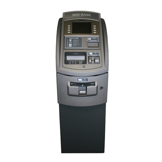
NH-1800CE 3. Hardware Specifications 3. Hardware Specifications 3.1 Dimensions Width x Length x Height : 410 x 580 x 1304 (mm) Fig. 3.1 NH-1800CE Dimension 3- 2... -
Page 15: Component Locations
NH-1800CE 3. Hardware Specifications 3.2 Component Locations Customer Display 4 X 2 Function Key (8”TFT LCD) Optional Panel (Not Defined) EMV Level-1 DIP MCU Voice Guidance Jack (Option) Cash Dispenser Fig. 3.2 Component Location 3- 3... -
Page 16: Lcd & Customer Keypad
NH-1800CE 3. Hardware Specifications 3.3 LCD & Customer Keypad Fig 3.3 LCD & Customer Keypad Screen Size : 8.0 Wide TFT Color Resolution : 800 600 pixels Keypad 10 Alphanumeric ,,4, CANCEL, CLEAR, ENTER, BLANK Keypads ... -
Page 17: Cash Dispenser Unit
NH-1800CE 3. Hardware Specifications 3.4 Cash Dispenser Unit 3-Cassette Cash Dispnesr 1-Casstte Cash Dispenser Fig. 3.4 Cash Dispensing Unit Cash Dispensing Unit • Manual shutter (Tray type) • Dispensing speed: 4 notes/second • Support 1 cassette / up to 3 cassettes (optional) •... -
Page 18: Receipt Printer
NH-1800CE 3. Hardware Specifications 3.5 Receipt Printer Fig. 3.6 Receipt Printer Receipt Printer 3" Thermal line printer with cutter 100mm/sec Printing Speed Semi-Automatic roll paper setting Support graphics / Bar Code printing See Appendix C : RECEIPT PAPER SEPECIFICATIONS ... -
Page 19: Magnetic Card Reader
NH-1800CE 3. Hardware Specifications 3.6 Magnetic Card Reader Fig. 3.7 Magnetic Card Reader Magnetic Card Reader Dip type Card Reader (ISO Track 1 & 2 Read) IC CARD Supporting / EMV Ready Readable ejection speed : 6 inches ~ 39.3 inches/second ... -
Page 20: Main Control Board
NH-1800CE 3. Hardware Specifications 3.7 Main Control Board Fig. 3.8 Main Control Board CPU : X-Scale PXA270 520MHz Memory : SDRAM (64MB), Flash Memory (64 MB) , NV-RAM : 512 KB Operating system : Windows CE Serial ports : 7 Ports ... -
Page 21: Operating Environment
50/60Hz , 100 Watt Power Connections The NH-1800CE ATM must be connected to a dedicated power circuit. This circuit must consist of LINE, NEUTRAL and GROUND leads connected directly to the power circuit breaker panel. This circuit cannot be shared with any other equipment. -
Page 22: Installation
NH-1800CE 4. Installation Chapter 4. Installation 4- 1... -
Page 23: Installation Requirements And Necessary Tools
NH-1800CE 4. Installation 4. Installation 4.1 Installation Requirements and Necessary Tools Installation conditions and space Following conditions should be met before installing equipment. 40°F - 95°F 1) Temperature while operating should be between 2) Relative humidity while operating should be between 15% < RH < 85%, Non-Condensed 3) Avoid locations where intense direct light is reflected off the LCD screen. - Page 24 NH-1800CE 4. Installation Fig. 4.2 Installation space #2 (Side view) Tools required for installation In order to move the machine and place it in a proper location, you should seek the help of professionals trained in moving heavy equipment.
-
Page 25: Unpacking
NH-1800CE 4. Installation 4.2 Unpacking Unpack the machine on top of the palette. Cut the straps that are fastened around the box with a knife. (refer to Fig. 4.3) (Be careful when cutting the straps.) Use an appropriate tool to remove the nails from the palette. (refer to Fig. 4.4) Remove the lid, then box from the top. -
Page 26: Physical Installation
NH-1800CE 4. Installation 4.3 Physical Installation To install the NH-1800CE ATM, perform the following steps. Place the “ Anchor bolts locate sheet ” at the place where the machine is to be installed. (refer to Fig. 4.5) Place the system on a flat surface, the system has a tendency to tip over if the surface is over 10 degrees. - Page 27 NH-1800CE 4. Installation Fig. 4.5 Anchor diagram of NH-1800CE ATM 4- 6...
- Page 28 NH-1800CE 4. Installation Fig. 4.6Making a surface level of ATM 4- 7...
-
Page 29: Hardware Installation
1) Verify the power voltage (110/220V) to be used and set the appropriate voltage on the power supply. 2) Verify that the telephone line to be used for the ATM is in proper working order. Hyosung recommends the use of shielded phone line in locations with close proximity to other appliances. -
Page 30: Operating Instructions
NH-1800CE 5. Operating Instructions Chapter 5. Operating Instructions 5 - 1... -
Page 31: Opening And Closing The Door
NH-1800CE 5. Operating Instructions 5. Operating Instructions 5.1 Opening and Closing the Door 5.1.1 How to open the electronic lock 1) Insert the key into the lock and turn it clockwise to open the front bezel. The default combination for Electronic Lock is 1-2-3-4-5-6. - Page 32 NH-1800CE 5. Operating Instructions 5.1.2 Opening and Closing the Front Panel 1) Insert the Front Panel key and turn it clockwise. 2) Please pull the Front Panel outward. 3) Take the reverse order of above description to close the Front panel.
- Page 33 NH-1800CE 5. Operating Instructions A. Optional : Dial Lock Opening and Closing the Security Cover and Door 1) Turn the Security Cover key clockwise to open the Security Cover. 2) To unlock the Combination Lock, please refer to A-2 and A-3.
- Page 34 NH-1800CE 5. Operating Instructions A-2 How to open the mechanical combination lock Make sure that this lock would be set 50-25-50 as factory default setting. 1) Turn to the counterclockwise for more than four times and set to “50.” 2) Turn to the clockwise and stop at “25” at the third times.
- Page 35 NH-1800CE 5. Operating Instructions A-3 How to set the new password For example, let's assume that you would like to set the following number (10-50-70) 1) Open the safe door as described in the above. 2) To close the mechanical lock, turn the handle to clockwise with the door opening 3) Turn to the counterclockwise for more than four times and set to “50”...
- Page 36 NH-1800CE 5. Operating Instructions Fig.5.4 Fig.5.5 7) Turn to the counterclockwise more than four times and position at left scale indicator to “10” (target number to change). 8) Turn to the clockwise for three times and position the scale to “50” (target number to change).
- Page 37 NH-1800CE 5. Operating Instructions Note: Do not use number 25 – 35 as the last password number. Fig.5.8 10) When password setting is completed, turn the change bar counterclockwise and remove it from the safe as shown in the Fig.5.9.
-
Page 38: Replenishing The Cash Cassette
NH-1800CE 5. Operating Instructions 5.2 Replenishing the Cash Cassette 1) With one hand holding the cassette handle and the other hand supporting the cash cassette from bottom, pull it up and out carefully. 2) Place the cash cassette on a flat level platform and turn the cassette key clockwise to unlock the cassette cover. - Page 39 NH-1800CE 5. Operating Instructions 4) Replenish the cassette (Take note as below) 5) Unlock the cash plate by pulling it again and move it smoothly. [Precaution!] Be careful not to hurt your hand when cash plate is released. NOTE : 1.
- Page 40 NH-1800CE 5. Operating Instructions 6) Close the cassette cover and turn the cassette key counter clock-wise until it is locked. Remove the key when it is locked. 7) With one hand holding the cassette handle and the other hand supporting the cassette from the...
-
Page 41: Emptying The Reject Bin
NH-1800CE 5. Operating Instructions Emptying the Reject Bin Emptying Reject box in Cash Dispenser 1) Insert the reject box key, turn it clockwise. 2) Open the lid in reject box. 3) Take bills in reject box and turn the key counter clockwise to close the box lid. -
Page 42: How To Clear Jam
NH-1800CE 5. Operating Instructions 5.4 How to Clear Jam Cash Dispenser 1) Pull the rail of CDU outward while pressing the white button on the CDU. 2) Lift up the upper cover of CDU. 3) Turn the pulley located in left upper in order to... - Page 43 NH-1800CE 5. Operating Instructions 4) Take out the jammed note carefully. 5) Remove the cash cassettes. 6) Remove the jammed note inside CDU body carefully. < Removing note jam in cash dispenser> 5 - 14...
-
Page 44: Loading The Receipt Paper
NH-1800CE 5. Operating Instructions 5.5 Loading the Receipt Paper 1) Open the Front Panel with key and pull this outward completely with hands. (Please see the Chapter 5.1.2) 2) Prepare the new paper roll. Please see the NOTE described below... - Page 45 NH-1800CE 5. Operating Instructions 4) The shiny side of the paper should be faced up to be printed properly and the metallic tension guide should be surrounded with paper to reduce the tension during feeding 5) Insert the leading edge of paper into the loading guide of the receipt printer slowly.
- Page 46 NH-1800CE 5. Operating Instructions NOTE: THE BASIC MECHANISM OF RECEIPT PRINTER 5 - 17...
-
Page 47: How To Clear A Receipt Jam
NH-1800CE 5. Operating Instructions 5.6 How to Clear a Receipt Jam 1) Open the Front Panel with key and pull this outward completely with hands. To remove a jammed paper inside transport path, press the green lever down to release the lower roller assembly. -
Page 48: Operator Functions
NH-1800CE 6. Operator Function 6. Operator Function 6- 1... -
Page 49: Password For Entering Supervisor Mode
NH-1800CE 6. Operator Function 6.1 PASSWORD FOR ENTERING SUPERVISOR MODE - Function Key Location on ATM - To enter Supervisor mode press the ENTER, CLEAR, CANCEL, 1, 2 and 3 keys in order. The default password is “555555”(6 digits). The default password is changeable in Supervisor mode. - Page 50 NH-1800CE 6. Operator Function Please make sure that default password should be changed to different password for your security as soon as this machine is installed at field site. ▪Authorities for each Mode Working Management Function Authority Main Sub1 Sub2...
- Page 51 NH-1800CE 6. Operator Function Working Management Function Authority Main Sub1 Sub2 Sub3 Sub4 Sub5 4ST CASSETTE ○ CURRENCY APPLY ○ CUSTOMER HEADER1 ○ ○ RECEIPT SETUP HEADER2 ○ ○ HEADER & TAIL TAIL ○ ○ CHANGE RECEIPT ADDRESS1 ○ ○...
- Page 52 NH-1800CE 6. Operator Function Working Management Function Authority Main Sub1 Sub2 Sub3 Sub4 Sub5 COMMUNICATION ○ HEADER COMMUNICATION ○ CRC OPTION ○ REVERSAL ○ RETRY COUNT OPTIONAL SETUP MOD10 ○ YEAR ○ ○ ○ ○ ○ ○ MONTH CLOCK SETUP ○...
- Page 53 NH-1800CE 6. Operator Function Working Management Function Authority Main Sub1 Sub2 Sub3 Sub4 Sub5 ○ ○ ○ REBOOT RESET ALL ○ ○ ○ RESET ○ ○ ○ ○ CLEAR ALL ○ ○ CLEAR SETTING ○ ○ CLEAR JOURNAL CLEAR NVRAM ○...
-
Page 54: Supervisor Menu
NH-1800CE 6. Operator Function 6.2 SUPERVISOR MENU The following screen below is the main screen of Supervisor mode. Supervisor mode in this machine is largely composed of ATM Status and Function A. ATM Status 1) Machine name, 2) Country Code... - Page 55 NH-1800CE 6. Operator Function B. Functions 04) REPLENISH 05) CONFIGURE 06) JOURNAL 07) DIAGNOSTICS 08) REPORT 09) RCOPY 23) REBOOT 33) RESET ALL 44) RESET 98) CLEAR NVRAM 99) IN SERVICE In order to move to the in-service mode, press '99' and then <Enter> key in sequence.
- Page 56 NH-1800CE 6. Operator Function C. Field Values CLASS VALUE Remarks MACHINE KIND 1800CE COUNTRY CODE New Zealand DOOR STATUS DOOR OPEN DOOR CLOSED LINE TYPE TCP/IP DIAL-UP MESSAGE FORMAT STANDARD1 STANDARD2 STANDARD3 ERROR CODE [00000(00)] HARDWARE STATUS CST1 BILLS COUNT(928($20)
-
Page 57: Replenish
NH-1800CE 6. Operator Function MEDIA STATUS CST1 MISSING NORMAL EMPTY FULL CST2 Not Available CST3 Not Available CST4 Not Available RETRACT RETRACT COUNT(CDU) – (0) RETRACT COUNT(MCU) – (0) MISSING NORMAL EMPTY Not Available 6.3 REPLENISH This menu contains TOTAL, ADD CASH, and PRINT CASH. Please press function key beside menu button to go to next screen. - Page 58 NH-1800CE 6. Operator Function 6.3.1 TOTAL This menu contains DAY TOTAL, TRIAL DAY TOTAL, CASSETTE TOTAL and TRIAL CASSETTE TOTAL. Please press function key beside menu button to operate related function. To go back to the previous screen, just press the <Cancel> key in pinpad.
- Page 59 NH-1800CE 6. Operator Function 6.3.2 ADD CASH You can select the cassette to add note count by pressing function key beside menu button. (Cassette numbers are designated from top to bottom). Input the note count you want to add and press the <ENTER>...
-
Page 60: Configure
NH-1800CE 6. Operator Function 6.4 CONFIGURE This menu contains HOST SETUP, TRANSACTION SETUP, CUSTOMERSETUP and SYSTEM SETUP. Please press function key beside menu button to go to next screen. To go back to the previous screen, just press the <Cancel> key in pinpad. - Page 61 NH-1800CE 6. Operator Function 6.4.1 HOST SETUP [DIALUP] This host setup menu contains TELEPHONE NUMBER, HEALTH CHECK MESSAGE, REMOTE MONITOR, TERMINAL ID, ROUTING ID and SERIAL NUMBER. [TCP/IP] This host setup menu contains HEALTH CHECK MESSAGE, REMOTE MONITOR, TERMINAL ID, ROUTING ID, SERIAL NUMBER and HOST ADDRESS Please press function key beside menu button to go to next screen.
- Page 62 NH-1800CE 6. Operator Function [TCP/IP] 6.4.1.1 TELEPHONE NUMBER (Only Dial-up) If you press each button on this menu, phone number of host can be input. You can input character, number and special symbol up to 1~20 digits by using '<' or '>'.
- Page 63 NH-1800CE 6. Operator Function 6.4.1.2 HEALTH CHECK MESSAGE If you press 'HOST SEND' button, either "ENABLE" or "DISABLE" can be selected. ATM sends its status periodically to the host when “Host Send” is set up to “Enable”. The interval is dependant on “Message Send Interval”.
- Page 64 NH-1800CE 6. Operator Function [DIAL-UP] [TCP/IP] 6- 17...
- Page 65 NH-1800CE 6. Operator Function 6.4.1.3.1 RMS EN/DISABLE (Only TCP/IP) - Display which is to set the RMS port for the reception on standby of the ATM. [TCP/IP] 6- 18...
- Page 66 NH-1800CE 6. Operator Function 6.4.1.3.2 RMS STATUS SEND EN/DISABLE - Display which is to set the function to transfer STATUS to RMS from the ATM. [DIAL-UP] 1) RMS STATUS SEND - Display whether RMS STATUS SEND function is Enable or not.
- Page 67 NH-1800CE 6. Operator Function [TCP/IP] 1) RMS STATUS SEND - Display whether RMS STATUS SEND function is Enable or not. 2) USE URL - Display whether to use URL when inputting RMS ADDRESS. 3) RMS INTERVAL - Display RMS STATUS SEND cycle (unit : time) - Input the number from 1 to 24.
- Page 68 NH-1800CE 6. Operator Function [In case of “URL DISABLE”] 6.4.1.4 TERMINAL ID This function is used to set the Terminal ID Number of ATM. Character, number or special symbol can be input up to 1~8(STD1, 2, EPS) or 1~15(STD3) digits by using '<' or '>'.
- Page 69 NH-1800CE 6. Operator Function 6.4.1.5 ROUTING ID This function is used to set the Routing ID Number of ATM. Routing ID refers to the Bank ID. This field is contained to Standard 1, Standard 2 and EPS format. Character, number or special symbol can be input up to 1~6 digits by using '<' or '>'. This value is saved by pressing<ENTER>...
- Page 70 NH-1800CE 6. Operator Function 6.4.1.6 SERIAL NUMBER This function is used to set the Machine Serial Number. The Machine Serial Number is used when RMS connects to ATM. RMS sends the Machine Serial Number to ATM and ATM compares it. If it is different, ATM disconnects impromptu.
- Page 71 NH-1800CE 6. Operator Function 6.4.1.7.1 HOST ADDRESS HOST ADDRESS contains IP ADDRESS (URL) #1, PORT NUMBER #1, IP ADDRESS (URL) #2, and PORT NUMBER #2. Number can be input. This value is saved by pressing <ENTER> key, on the other hand to go back to the previous screen, just press the <Cancel> key in pinpad.
- Page 72 NH-1800CE 6. Operator Function 6.4.2 TRANSACTION SETUP This host setup menu contains DISPENSE LIMIT, LOW CURRENCY CHECK, and DENOMINATION. You can enter each sub menu by pressing each button. To go back to the previous screen, just press the <Cancel> key in pinpad.
- Page 73 NH-1800CE 6. Operator Function 3) SET DENOMINATION function is used to set the denomination of note to be set in the cassette. Please press function key beside menu button if you want to select the cassette to set the denomination of note. Input the note value you want and press the <ENTER> key in the pinpad. If you completed the all cassette setting, you have to press APPLY button to effect the value changes.
- Page 74 NH-1800CE 6. Operator Function 6.4.3 CUSTOMER SETUP This customer setup menu contains CHANGE MESSAGE, SURCHARGE MODE, BIN LIST, ADVERTISEMENT, COUPON, SELECT HOST and OPTIONAL SETUP. Please press function key beside menu button to operate selected function. To go back to the previous screen, just press the <Cancel>...
- Page 75 NH-1800CE 6. Operator Function Refer to figure of the Sample Receipt below for the location of the messages. The default receipt format will not include any messages. Spanish transactions will be printed in English. -Location of Messages on Receipt- 6.4.3.1 CHANGE MESSAGE CHANGE MESSAGE menu has each of two sub menu.
- Page 76 NH-1800CE 6. Operator Function 1) RECEIPT HEADER & TAIL RECEIPT has function of guide comment and explanation in the HEADER and TAIL. If you push the HEADER1, you can enter the message on the HEADER 1. As the same as HEADER1, you can push and insert the message on the HEADER 2.
- Page 77 NH-1800CE 6. Operator Function 2) RECEIPT ADDRESS & PHONE NUMBER RECEIPT function includes setting the information of ADDRESS and PHONE NUMBER. You can enter the message when you push the ADDRESS 1. And in case of pushing ADDRESS 2, you can insert the message in ADDRESS 2.
- Page 78 NH-1800CE 6. Operator Function 6.4.3.2 SURCHARGE MODE The SURCHARGE MODE contains the enable/disable of the surcharge warning screen and setting the surcharge amount and surcharge owner. When the surcharge mode is disabled and also if the swiped card data contains BIN number that was entered during installation, the surcharge warning message will not be displayed.
- Page 79 NH-1800CE 6. Operator Function 6.4.3.3 BIN(Bank Identification Number) LIST The “BIN LIST” is used to register the bank identification number. When the cardholders make transaction with the given BIN code, ATM doesn’t request any additional fee. However, it is necessary to confirm the connected host because host will decide whether it uses or not You can input and edit it by using such as ADD, DELETE, EDIT, DELETE ALL, PREV, NEXT button.
- Page 80 NH-1800CE 6. Operator Function [DIALUP] STANDARD 3 [TCP/IP] SELECT HOST menu contains COMMUNICATION, MESSAGE FORMAT, TCPIP TYPE, REVERSAL RETRY COUNT and STANDARD3 OPTION (STANDARD3) [TCP/IP] – In case of selecting VISA FRAMED for TCP/IP TYPE 6- 33...
- Page 81 NH-1800CE 6. Operator Function [TCP/IP] – In case of selecting STANDARD TCP/IP for TCP/IP TYPE 6.4.3.4.1 COMMUNICATION COMMUNICATION function is used to change Dial-UP and TCP/IP (default) mode 6- 34...
- Page 82 NH-1800CE 6. Operator Function 6.4.3.4.2 VISA FRAMED CONTROL OPTION VISA FRAMED CONTROL OPTION contains GENERAL, EOT OPTIONAL, NO EOT REQUIRED (default) and NO ENQ REQUIRED functions. You can select one of these options 6- 35...
- Page 83 NH-1800CE 6. Operator Function 6.4.3.4.3 STANDARD3 OPTION STANDARD3 OPTION contains STATUS MONITORING, COMMUNICATION HEADER, COMMUNICATION ID and CRC EN/DISABLE. In case of TCP/IP communication CRC EN/DISABLE option can be configured. 6.4.3.4.4 MESSAGE FORMAT You can select one of message types to communicate with a data processing company or bank in this menu (STANDARD1, STANDARD2, STANDARD3 and EPS).
- Page 84 NH-1800CE 6. Operator Function 6.4.3.4.5 TCP/IP TYPE In this menu, you can change TCP/IP TYPE and can decide whether ‘ENABLE’ or ‘DISABLE’ about SSL OPTION. There are three kind of TCP/IP type in this TCP/IP COMMUNICATION menu (STANDARD TCP/IP, VISA FRAMED TCP/IP, and ACK CONTROLLED TCP/IP).
- Page 85 NH-1800CE 6. Operator Function 6.4.3.5 ADVERTISEMENT SETUP ADVERTISEMENT SETUP function provides six different advertisement screens. If you press the TIMER button, you can change the advertisement display timer and the range is between 5 and 30. If you press other function key beside menu button, you can select ENABLE or DISABLE in the advertisement screen.
- Page 86 NH-1800CE 6. Operator Function 6.4.3.6 COUPON SETUP COUPON SETUP menu contains COUPON1 SETUP, COUPON2 SETUP, COUPON3 SETUP, COUPON4 SETUP, COUPON5 SETUP and COUPON6 SETUP. Please press function key beside menu button to go to next screen. To go back to the previous screen, just press the <Cancel> Key in pinpad.
- Page 87 NH-1800CE 6. Operator Function 6.4.4 SYSTEM SETUP [DIALUP] This system setup menu contains SET CLOCK, CHANGE PASSWORD, SPEAKER VOLUME, MODEM SETUP, MODEM TEST and LANGUAGES. TCP/IP] This system setup menu contains SET CLOCK, CHANGE PASSWORD, SPEAKER VOLUME, ATM IP SETUP and LANGUAGES.
- Page 88 NH-1800CE 6. Operator Function 6.4.4.1 SET CLOCK You can set system date and time by pressing YEAR, HOUR, MONTH, MINUTE and DAY button. If you press each menu, the cursor will be positioned and you can change the value. This value is saved by pressing <ENTER>...
- Page 89 NH-1800CE 6. Operator Function 1) OPERATOR PASSWORD This menu enables you to change current operator password as new one. To change the current password, you should input the proper one in current password field. The factory default value of operator password is "111111".
- Page 90 NH-1800CE 6. Operator Function 3) MASTER PASSWORD This menu enables you to change current master password as new one. To change the current password, you should input the proper one in current password field. The factory default value of master password is "555555".
- Page 91 NH-1800CE 6. Operator Function 6.4.4.4 MODEM SETUP The INITIAL STRING function is used to edit the modem initial string when the special circumstance is required by a nonstandard modem initial string. Before editing the initial string, consult with service personnel.
- Page 92 NH-1800CE 6. Operator Function 6.4.4.6 ATM IP SETUP ATM DHCP SETUP menu contains STATIC IP and DHCP EN/DISABLE button. If you press STATIC IP button, you can go to sub menu, which is ATM STATIC IP SETUP. And pressing ATM DHCP EN/DISABLE button will change DHCP status, ENABLE to DISABLE, or DISABLE to ENABLE.
-
Page 93: Journal
NH-1800CE 6. Operator Function 6.5 JOURNAL JOURNAL menu contains PRINT JOURNAL, VIEW JOURNAL, LAST X PRINT and CLEAR JOURNAL. - PRINT JOURNAL: The PRINT JOURNAL function is used to print out all the journals which have not been printed from the last printed journal. If you want to stop printing, you may stop it by pressing <CANCEL>... - Page 94 NH-1800CE 6. Operator Function 6.5.1 VIEW JOURNAL You can see the various kinds of journal date by using each field and button. The VIEW function is used to display the Journal data on the customer screen. The Journal record will be displayed on the screen.
- Page 95 NH-1800CE 6. Operator Function 6.5.1.1 SEARCH JOURNAL You can search a specific journal with a journal index and see it if the index is valid. 6.5.2 LAST X PRINT - You can print the latest X journals and you can stop it by pressing <CANCEL> key.
-
Page 96: Diagnostics
NH-1800CE 6. Operator Function 6.6 DIAGNOSTICS - Function Key Location on ATM - 6.6.1 DIAGNOSTIC MAIN - From the select menu, press 7(Diagnostics) and press ENTER. - Wait until diagnostics menu screen appears as the below picture. - You can easily check the status of each device like cash dispenser, card reader, receipt printer, pinpad, others. - Page 97 NH-1800CE 6. Operator Function 6.6.1.1 TEST CASHDISPENSER - On the diagnostics menu, press F1 -“Cash Dispenser” button. Wait until Cash Dispenser menu screen appears as the below picture. 1) INITIALIZE To initialize Cash Dispenser , just press F1 in Cash Dispenser TEST.
- Page 98 NH-1800CE 6. Operator Function Show the Cash Dispenser Sensor position. And It will get back upper menu, in other words Cash Dispenser Menu if you Press F8 key. 3) DISPENSE To dispense bills from Cash Dispenser, just press F3 in Cash Dispenser TEST.
- Page 99 NH-1800CE 6. Operator Function 4-5) CDU SET START To execute CDU Setting command for Cash Dispenser, press F6 after selecting the setting up. Then below screen will be shown. 4-5-1) CANCEL To cancel setting command execution, press F1 in above screen.
- Page 100 NH-1800CE 6. Operator Function 6.6.1.2 TEST RECEIPT PRINTER - On the diagnostics menu, press F2 “Receipt Printer” button. Wait until Receipt Printer menu screen appears as the below picture. 1) INITIALIZE To initialize Receipt Printer, just press F1 in Receipt Printer TEST.
- Page 101 NH-1800CE 6. Operator Function 3) TEST PRINT To Test Print Receipt Printer, just press F3 in Receipt Printer TEST. 4) TEST EJECT To Eject Receipt Printer, just press F4 in Receipt Printer TEST. 5) TEST AUTOLOAD To automatically load Receipt Printer, just press F5 in Receipt Printer TEST.
- Page 102 NH-1800CE 6. Operator Function 6.6.1.3 TEST CARDREADER On the diagnostics menu, press F3 “Card Reader” button. Wait until Card Reader menu screen appears as the below picture. 1) IC READ To test read IC card on card reader, just press F5 in Card Reader TEST.
- Page 103 NH-1800CE 6. Operator Function 2) READ To test read magnetic card on card reader, just press F6 in Card Reader TEST. 3) EXIT To finish testing about Card Reader, just press F8 in Card Reader TEST. And It will go back to Main Screen.
- Page 104 NH-1800CE 6. Operator Function 6.6.1.4 TEST PINPAD On the diagnostics menu, press F4 “PinPad” button. Wait until PinPad menu screen appears as the below picture. Press ‘Start’ button and enter the 1st password to execute program. (Default password is ‘000000’) ...
- Page 105 NH-1800CE 6. Operator Function 2) EXIT To finish testing PinPad, just press F8 in PinPad TEST. And It will get back Main Screen. 6- 58...
- Page 106 NH-1800CE 6. Operator Function 6.6.1.5 TEST OTHERS On the diagnostics menu, press F5 “OTHERS” button. Wait until OTHERS menu screen appears as the below picture. 1) TEST SENSOR On the OTHERS menu, press F1 “Sensor” button. Wait until Sensor menu screen appears as the below picture.
- Page 107 NH-1800CE 6. Operator Function 1-1) ENABLE EVENT To check the status of sensor, just press F5 in Enable Event Button. 1-2) DISABLE EVENT To turn the sensor to be disable, just press F6 in Disable Event Button. 1-3) EXIT To finish testing sensor, just press F8 in Sensor TEST. And It will get back OTHERS Screen.
- Page 108 NH-1800CE 6. Operator Function To finish testing lamp, just press F8 in Lamp TEST. And It will get back OTHERS Screen. 6.6.1.6 EXIT DIAGNOSTIC On the diagnostics menu, press F8 “EXIT” button to exit this mode completely. And then ATM will reboot in seconds and welcome screen will be displayed automatically.
-
Page 109: Report
NH-1800CE 6. Operator Function 6.7 REPORT This report menu consists of 2 sub-menus. You can print out all information regarding each device as well as system value set up. If you want to go back the previous screen, just press the <Cancel> key 6.7.1 SW VERSION... - Page 110 NH-1800CE 6. Operator Function 6.7.2 PRINT ALL SETUP ▪PRINT ALL SETUP List [ DIAL – UP] ITEM DESCRIPTION REMARKS Date CURRENT DATE & TIME HOST PROCESSOR HOST PROTOCOL TYPE NETWORK TYPE DIAL-UP , TCP/IP VISA FRAMED OPTION VISA FRAMED OPTION...
- Page 111 NH-1800CE 6. Operator Function MASTER KEY INDEX MKEY LIST [ TCP / IP] ITEM DESCRIPTION REMARKS Date CURRENT DATE & TIME HOST PROCESSOR HOST PROTOCOL TYPE NETWORK TYPE DIAL-UP , TCP/IP TCP/IP TYPE TCP/IP TYPE CRC CHECK MODE CRC OPTION...
-
Page 112: Rcopy(Remote Copy)
NH-1800CE 6. Operator Function HEALTH CHECK OPTING RMS OPTION KEY MODE MASTER KEY INDEX MKEY LIST 6.8 RCOPY(Remote Copy) You can back up a various kinds of journal, log and NVRAM data you want in this menu. Please make sure that USB memory stick is connected into USB slot before pressing the button. When BACKUP JOURNAL COPY TO USB, BACKUP LOG TO USB or BACKUP NVRAM button is selected, this data will be sent into USB flash drive. - Page 113 NH-1800CE 6. Operator Function 6.8.1 SW UPDATE This is a menu to update software. Please make sure that new software is included in the USB flash drive and is connected into USB slot before implementing it. When SW UPDATE button is selected, new software in the USB drive is transferred to a directory of ATM and ATM will start to reboot automatically.
-
Page 114: Key Management
NH-1800CE 6. Operator Function 6.9. KEY MANAGEMENT 6.9.1 Start Screen Fig. 6.1 Start Screen (Enter Password) From the Supervisor Menu press Diagnostics. From Diagnostics select Pinpad Press ‘Start’ button and enter the 1st password to execute program. (Default password is ‘000000’) ... - Page 115 NH-1800CE 6. Operator Function 6.9.2 Main Screen Fig. 6.2 Main Screen Change Password Change the password by executing “Change Password”; Set Key Mode This ATM supports the capability for DES (Single-DES, Dual-DES, Triple- DES, MAC, and Unique Key). You can select DES mode by entering this function.
- Page 116 NH-1800CE 6. Operator Function 6.9.3 Setting the Key Mode ☞ Mapping table to enter DES keys Customer Keyboard Number DES Key (EPP) ◀ ▶ Space (Blank) Cancel Clear Enter Table. 6.1 Key Mapping Table ☞ There are 2 kinds of customer keyboard(EPP). The difference is the position of ‘Enter’, ‘Clear’...
- Page 117 NH-1800CE 6. Operator Function Fig. 6.3 Set Key Mode Screen 1. Enter mode number(See “Key Mode Information” on screen) Mode No. Mode Information Singe Master Key(DES) Dual Master Key(DES) Unique Key(DES) Master Key(TDES) Unique Key(TDES) Single Master(Mac, DES) Unique Key(Mac, DES)
- Page 118 NH-1800CE 6. Operator Function 2. Enter “PIN Format” (Default is “0”) - 0: ISO0 - 1: NCR/DIEBOLD 3. Enter ‘Part Number” (Default is “0” and do not need consider this field.) 4. Enter “PIN Pad Data” (0~F) 5. Submit by touching “EXECUTE”. If submission is successful, “EXECUTION SUCCESS”...
- Page 119 NH-1800CE 6. Operator Function 6.9.4 Key Entry Fig. 6.4 Enter Master Key Screen 1. Enter “1” at “Part number” field. (Part A : 1, Part B : 2) The cardholders can not make the financial transaction until the entry of Part A and Part B is finished.
- Page 120 NH-1800CE 6. Operator Function Part A key. 9. The message, “PART A Key (RIGHT) input finished! Please press execute button to verify.” will be displayed on the screen. Submit by touching “Execute” button. 10. The message, “Verify Key”, will be displayed on the screen with a cursor blinking. Enter the right half of the Part A key again.
- Page 121 NH-1800CE 6. Operator Function 6.9.5 Confirmation of the entered keys Fig. 6.5 Check Key Screen From KEY MANAGEMENT select CHECK KEY STATUS. Use the Check Key menu to determine which index keys (or partial keys) have been installed on. As shown above, there are full keys installed on positions #0 and #15.
- Page 122 NH-1800CE 6. Operator Function 6.9.6 Change password for execution program Fig. 6.6 Change Password Screen If you want to change password for Key Management, press ‘Change password’ button in the main screen. And press ‘Password #1’ and “Password #2” button to change password...
- Page 123 NH-1800CE 6. Operator Function ● Main Screen Fig. 6. 8 Key Management Main Screen ☞ Device Test : You can test the normal state of customer keyboard (EPP) by pressing keys. The key value will be displayed on screen whenever you press a key.
- Page 124 ☞ “PIN Format” defines the type of algorithm (0 : ISO-0, 1 : Diebold). Nautilus Hyosung recommends strongly no changes. Default value is “0”. ☞ “PIN Pad Data” is a padding data in EPP itself. Nautilus Hyosung recommends strongly no changes. Default value is “0”.
- Page 125 NH-1800CE 6. Operator Function DES Key Entry 1) Select “Enter Key”, “Master Key”, “Unique Key”, Mac Key sequentially ☞ Master Key : Single DES Unique Key Mac Key ☞ Master Key (Triple) : Triple DES Unique Key (Triple) Mac Key (Triple) 2) Enter “Part Number”, “Block #”, “Key Index”...
- Page 126 NH-1800CE 6. Operator Function 3) Enter 16 left half digits for Part A using customer keyboard(EPP) press “Execute” button to submit. ☞ Re-entering of the same values will be requested to verify that you entered correctly. 4) Enter 16 right half digits for Part A using...
-
Page 127: Software Installation
NH-1800CE 6. Operator Function 6.10. Software Installation 6.10.1 How to download OS 6.10.1.1. OS Image Download (SD: Secure Digital card) a. Copy OS Image file, nh270nk.bin, to SD card. ٛ b. Insert SD card into SD card slot on the board. - Page 128 NH-1800CE 6. Operator Function d. Connect Debug port in machine and PC. Debug port feature is as follows. COM0 ~ COM5 COM6 : Debug Port LAN Front Panel * RJ-45 CONNECTOR BOX PIN ASSIGN 6- 81...
- Page 129 NH-1800CE 6. Operator Function COM1 COM3 COM5 LAN COM0 COM2 COM4 COM6 COM0 ~ COM2 : CPU Internal SERIAL ※ COM3 ~ COM6 : Extended SERIAL (ST16C654, 64byte ※ FIFO) ⓐ COM0 : SPR ٛ ⓑ COM1 : MCU ٛ...
- Page 130 NH-1800CE 6. Operator Function 6- 83...
- Page 131 NH-1800CE 6. Operator Function 6- 84...
- Page 132 NH-1800CE 6. Operator Function -> If USB cable is initially connected to the system from your PC, You need to install USB driver for newly found hardware. n. The completion and status of Download can be viewed in ESHELL. ٛ...
- Page 133 NH-1800CE 6. Operator Function 6.10.1.3 OS Image Download (In Case of Upgrade using SD memory card) a) Put nh270nk.bin file into root directory of SD memory card. b) Put SD memory card into SD memory card slot on the main panel.
- Page 134 NH-1800CE 6. Operator Function c) Power on ATM machine. d) Push two buttons on the left-bottom side. SERIAL 〈〈〈 LAN(MAC 〈〈〈 〈〈〈 Aging 〈〈〈 6- 87...
- Page 135 NH-1800CE 6. Operator Function e) Choose SD update menu. SD CARD 〉〉〉 FLICKER 〉〉〉 SENSOR 〉〉〉 Exit Test Menu 〉〉〉 f) Automatically, os is upgrading. 6- 88...
- Page 136 NH-1800CE 6. Operator Function g) After succeed, reboot ATM machine. 6- 89...
- Page 137 NH-1800CE 6. Operator Function 6.10.2. Application Software Installation Process Manually 6.10.2.1 When would manual install be used. General If necessary to upgrade application file from USB memory stick, in case of flash memory failed to be read or system boot image was reloaded, following process is required.
- Page 138 NH-1800CE 6. Operator Function - There are two ways to start installation from this screen. ٛ a. Press left function key button beside of “START” button ٛ b. Or move mouse cursor over the button to start installation. c. Total installation duration is about 7~8 minutes and below screen is displayed after completion.
- Page 139 NH-1800CE 6. Operator Function * If installation fails on any steps, operator must follow next steps to recover.(* 1.Format -> 2. AP Copy -> 3.NVRam Clear-> 4.Sound Test -> Ping Test) 3) Manual Execution (Mouse connection is required) a. Next screen is a picture containing several folders before USB memory stick is recognized.
- Page 140 NH-1800CE 6. Operator Function 6- 93...
- Page 141 NH-1800CE 6. Operator Function 4) Manual Execution : Formatting - By pressing “1.Format” button, it will start formatting flash memory. 5) Manual Execution: AP copy - The next step is executing application copying with “2.AP Copy” button. 6- 94...
- Page 142 NH-1800CE 6. Operator Function 6) Manual Execution: NVRAM Clear - NVRAM clear is executed by pressing “3.NVRAM Clear” button for clearing data. 7) Manual Execution: Sound Test - Sound Test is required to test whether current image is making sound.
- Page 143 NH-1800CE 6. Operator Function 8) Manual Execution: Ping Test - Followed Ping Test to check LAN card connectivity. * After all installation processes, operator needs to restart ATM. Summary Following information explains how software installation works: 1. Windows CE Operating System’s start up program will search file “WinATM.exe”...
- Page 144 NH-1800CE 6. Operator Function 6.10.3. Application Software Downloading from Supervisor Menu -After C procedure is done, you are able to enter Supervisor menu and ATM is ready to run. -Normally on supervisor menu, you are able to upgrade software application files using RCopy menu.
-
Page 145: Appendix
NH-1800CE 7. Appendix Chapter 7. Appendix 7- 1... -
Page 146: Summary Of Specification
NH-1800CE 7. Appendix 7. Appendix A. SUMMARY OF SPECIFICATION Item Specification Remarks (Option) X-Scale PXA270 520MHz Main Memory SDRAM 64 MB Controller Flash Memory 64 MB 128 MB Option NV-RAM 512 KB Operating System Windows CE Serial Ports 7 Ports... - Page 147 NH-1800CE 7. Appendix Audio guidance Support Speaker Additional ADA Audio guidance Option function Topper Advertising Panel Dimension (WXDXH) 410 X 580 X 1,300 Foot Print : 400(W) X 500(D) Dimension Access Type Front Access & Installation Anchor Bolt 16mm Environment...
-
Page 148: Bill Conditions
NH-1800CE 7. Appendix B. BILL CONDITIONS B.1 Acceptable condition Bill which is very clean and can readily be recognized as a true bill Bill that has sufficient life or sizing to be handled easily Bill which can be manually held straightly when one end is held by a hand and the bill is... - Page 149 NH-1800CE 7. Appendix B.2 Unacceptable condition Bill having serious wrinkles, torn or broken section wherein paper fiber is broken and separation begins Wrinkle Wrinkle Torn Torn Broken section Broken Section 7- 5...
- Page 150 NH-1800CE 7. Appendix Bill having adequate life or sizing, but stained seriously Stained Bill with holes (Perforated bill) Hole Bill ragged and cannot be held straightly when one end is supported by a hand 20mm 35mm When the bill is held by 20mm and the straightness of...
- Page 151 NH-1800CE 7. Appendix Bill with cellophane tape, scotch tape, etc Tape Bill with folds Fold Gradually curved bill (bills tied by hand seal, etc) Band seal 7- 7...
- Page 152 NH-1800CE 7. Appendix Bill with folded lines Case 1 Case 2 Case 3 ☞ Bill distortion should not exceed 10 mm 7- 8...
-
Page 153: Receipt Paper Specifications
NH-1800CE 7. Appendix C. RECEIPT PAPER SPECIFICATIONS C.1 Applicable Product This purchase specification applies to the receipt paper of 5050. C.2 Specification 1) Paper type: Thermal roll paper 2) Print color: Black C.3 Specification of the Receipt Paper 1) Paper type: Thermal roll paper 2) Print color: Black 3) Specification: Paper detects heat. - Page 154 NH-1800CE 7. Appendix C.4 Roll appearance 79.5± 0.5 (3.1±0.01 inch) (7.1 inch) Ø180 (0.9 inch) Ø22 Ø18 (0.7 inch) - All measurements are in mm. Fig. 7.2 External roll dimension Note 1) Store the paper roll separately to prevent damage to the paper.
- Page 155 NH-1800CE 7. Appendix C.5 Paper Handling Precautions 1) Store it away from high temperature and humidity If the paper is stored in a place where temperature is above 50 or humidity is above 90% RH, the ℃ coloring capability may deteriorate or the paper surface may inflate.
-
Page 156: Magnetic Card Specifications
NH-1800CE 7. Appendix D. MAGNETIC CARD SPECIFICATIONS Item ISO Card (Unit : Inch) Length Card Bending Magnetic Stripe Position Fig. 7. 3 Magnetic Card Specifications 7- 12... -
Page 157: Error Code Table
NH-1800CE 7. Appendix E. ERROR CODE TABLE E.1 Receipt Printer Error Code Description Trouble shooting 1106910 LOST SLIP", DEV_SPR 2001000 Receipt paper jam Remove any jammed paper from the printer. 2001200 Receipt printer feed plate open Close the feed plate. - Page 158 NH-1800CE 7. Appendix Error Code Description Trouble shooting Wait the time until the temperature of head 2080200 Receipt printer head overheated adequately slow down and try to initialize Remove jammed paper between printer head and 2080300 Receipt paper jam rollers 1.
- Page 159 NH-1800CE 7. Appendix Error Code Description Trouble shooting Paper cutter software check error detected A010800 Check for and remove any jammed paper. before executing command A080100 Open lever detected while executing command Remove any jammed paper. Check the thermal printer head and change if...
- Page 160 NH-1800CE 7. Appendix E.2 Card Reader Error Code Description Trouble shooting 8217091 Card in card reader Remove card 1101910 LOST CARD", DEV_MCU 9723010 Failed to open device Check the serial port or cable 9723016 Time out to receive data Check the serial port or cable...
- Page 161 NH-1800CE 7. Appendix E.3 Journal Printer Error Code Description Trouble shooting 1. Check communication cable connected properly 9721111 Off line status 2. Check power cable connected properly 9721112 On busy 1. Check printer’s working status 1. Recover printer’s mechanical Error...
- Page 162 NH-1800CE 7. Appendix E.4 Cash Dispenser Error Code Description Trouble shooting 1102910 LOST WITHDRAW CASH", DEV_CSH 1102920 LOST DEPOSIT CASH", DEV_CSH 1103910 LOST CARD & SLIP", DEV_MCU | DEV_SPR Insert or re-insert the cassette(s). Check cassette 2000100 No cassette sensor.
- Page 163 NH-1800CE 7. Appendix Error Code Description Trouble shooting Detecting CS2 Dark (Front Access Type:Reject 4001100 1. Remove notes on CS2 sensor 2. Clean CS2 box is opened.) CS4A sensor detects note in delivery path 1. Remove note from the CDU delivery path.2.
- Page 164 NH-1800CE 7. Appendix Error Code Description Trouble shooting CS1A, CS1B or CS13 sensor detects note in 1. Remove note from the CDU delivery path.2. 4002B00 delivery path before/after CDU dispenses Clean CS1A, CS1B and CS13 1. Initialize 2. Check Main Motor Encoder Slit 3.
- Page 165 NH-1800CE 7. Appendix Error Code Description Trouble shooting 1. Check the cassette catcher 4004000 Cassette is removed during dispensing 2. Set the cassette properly 1. Check notes in Reject Box 2. Rearrange notes in Cassette 3. Remove dust in CS15AB, CS31AB, CS41AB...
- Page 166 NH-1800CE 7. Appendix Error Code Description Trouble shooting 1. Check state of notes in reject box 2. Rearrange notes in cassette Continuous 3 times error if note is long 3. Check Index of notes 4004B00 (once tried, twice retried)=>Separated rejection 4.
- Page 167 NH-1800CE 7. Appendix Error Code Description Trouble shooting 1. Remove jammed notes 4005900 Initial jam time error 2. Clean the sensors (CS1~CS15) in cash dispenser 2 Cassette Miss Feed Error (Fail to reject bill 4005B00 separately.) 1. Check notes’ status in the reject box 2.
- Page 168 NH-1800CE 7. Appendix Error Code Description Trouble shooting Trying to dispense bills from 4th cassette but 4007D00 the 4th cassette doesn't installed. Something is detected on CS15AB sensor 4008000 before dispensing operation Something is detected in C15AB sensor during 4008100...
- Page 169 NH-1800CE 7. Appendix Error Code Description Trouble shooting Bills are passed on CS12~CS14 sensor - 400D100 Timeout[Jam], MB TTW 1. Remove the jammed notes 400FF00 Bill jam 2. Initialize Cash Dispenser communication failure during 1. Do RESET at Operator Function...
- Page 170 NH-1800CE 7. Appendix Error Code Description Trouble shooting 9719400 Invalid Cash Unit ID Reconfigure cash dispenser setup data 9719500 Invalid Cash Unit number Reconfigure cash dispenser setup data 9719600 The abnormal of the number of Cash Unit Reconfigure cash dispenser setup data 1.
- Page 171 NH-1800CE 7. Appendix Error Code Description Trouble shooting Cash Dispenser communication failure 1. Do RESET at Operator Function 9740000 during COM port open 2. Reboot ATM 9740101 In case incorrect cassette type is set. 9740102 In case nonexistent Note Index is set.
- Page 172 NH-1800CE 7. Appendix Error Code Description Trouble shooting DEV_Cash Dispenser FATAL ERROR 1. Reboot ATM 97924XX (WARNING) 2. Call your attendant 9799499 DISPENSER COUNT ERROR Check the sensor on cash dispenser E.5 Modem Error Code Description Trouble shooting D030000 Modem is not responding Check the modem controller.
- Page 173 NH-1800CE 7. Appendix E.6 Miscellaneous Error Code Description Trouble shooting 1030100 DEV_PIN (Key data error from host) Contact to host 2000400 Vault door open Close the vault door. Check door switch. Failed to connect communication between SP of Check if communication cable or COM port is not...
- Page 174 NH-1800CE 7. Appendix Error Code Description Trouble shooting 1. Reboot ATM 97221C6 PrintForm() offset is Invalid 2. Call your attendant 1. Reboot ATM 97221C7 Invalid Form (Too many Fields in the form) 2. Call your attendant 1. Reboot ATM 97221D1 Media is not Found 2.
- Page 175 NH-1800CE 7. Appendix Error Code Description Trouble shooting 1. Reboot ATM 97915XX DEV_BRM Timeover Error Code 2. Call your attendant 1. Reboot ATM 97916XX DEV_PBM Timeover Error Code 2. Call your attendant 1. Reboot ATM 97918XX DEV_PIN Timeover Error Code 2.
- Page 176 NH-1800CE 7. Appendix Error Code Description Trouble shooting 1. Reboot ATM 9799908 SCREEN ERROR 2. Call your attendant 1. Check power supply 991@@91 ON TRANSACTION POWER OFF 2. Check backup battery D000100 Error while modem initializing Check the modem connection and the modem test.
- Page 177 NH-1800CE 7. Appendix Error Code Description Trouble shooting D001900 SYSTEM ERROR Transaction was denied by host Check the transaction from the host and try again. D002000 Surcharge screen should have been displayed Check BIN List D002100 ROUTING LOOKUP PROBLEM Transaction was denied by host...
- Page 178 NH-1800CE 7. Appendix Error Code Description Trouble shooting Check the transaction from the host and try again. D008300 Can not Verify PIN Try different cards. Check the transaction from the host and try again. D008600 Can not Verify PIN Try different cards.
- Page 179 NH-1800CE 7. Appendix Error Code Description Trouble shooting D00A100 FS out (after available balance) Check the terminal setting from the host. D00A200 FS out (after surcharge amount) Check the terminal setting from the host. D00A300 FS out (after authorization response text) Check the terminal setting from the host.
- Page 180 NH-1800CE 7. Appendix Error Code Description Trouble shooting D00BB00 Balance amount Error D00BC00 Actual Surcharge Error D00BD00 Sequence Number MISMATCHED D00BF00 BUSINESS DATE Error D00C000 Settlement Error D00C100 Host Mac result error Check the key mode and MAC value D00C200...
- Page 181 NH-1800CE 7. Appendix Error Code Description Trouble shooting 1. Check modem and modem cable connection D140600 Disconnected by Congestion 2. Contact telephone company 1. Check modem and modem cable connection D140700 Disconnected by Incompatible 2. Contact telephone company 1. Check modem and modem cable connection...
- Page 182 NH-1800CE 7. Appendix Error Code Description Trouble shooting 1. Check modem and modem cable connection D170700 NAK retry error. 2. Contact telephone company 1. Check modem and modem cable connection D170800 Send retry error 2. Contact telephone company D170900 Modem initialize fail...
- Page 183 NH-1800CE 7. Appendix Error Code Description Trouble shooting D320400 Get Line ID Failed D320500 Modem Comport Failed D320600 Call Failed D320700 No Answer D320800 Modem Call Other Error D410000 CRC Mismatch Check telephone line connection D410100 No CRC Received Make sure that the host is using CRC...
- Page 184 NH-1800CE 7. Appendix Error Code Description Trouble shooting RMS Phone Number is not inputted in RMS F000E00 Enter RMS phone number. Enable F000F00 Terminal Number is not inputted Enter Terminal number. (required) F001000 Routing ID is not inputted Enter Routing ID. (required)
- Page 185 NH-1800CE 7. Appendix Error Code Description Trouble shooting 1. Check AC power status and environment POWERBA BATTERY LOW 2. Check UPS SDN0100 Service Panel (SPL) communication error Check the cables and connections. 7- 41...
- Page 186 NH-1800CE 7. Appendix E.7 Description for error code organization If an error occurs, you can understand cause of error through error code and help operator to judge situation. Below example is forms and contents for error code “5-40047(00)”. 1. 5 in front “-“ is procedure number, and you can analysis the procedure that an error occurs through that number.
-
Page 187: Installation Guide
NH-1800CE 7. Appendix F. Installation Guide F.1 Installation Requirements and Necessary Tools Installation condition and space Following conditions should be met before installing equipment. 1) Temperature while operating should be between 40°F - 95°F 2) Relative humidity while operating should be between 15% < RH < 85%, Non-Condensed 3) Avoid locations where intense direct light is reflected off the LCD screen. - Page 188 NH-1800CE 7. Appendix Fig. 7.5 Installation space #2 (Side view) Tools required for installation In order to move the machine and place it in a proper location, you should seek the help of professionals trained in moving heavy equipment.
- Page 189 This combination should be changed as soon as possible. Refer to Appendix B for instructions on changing the lock combination. After the anchor nuts are in place according to the anchor holes on the bottom of the NH-1800CE ATM, tighten the anchor bolts tightly. (refer to 7.6) 7- 45...
- Page 190 NH-1800CE 7. Appendix Fig. 7. 6 Anchor diagram of NH-1800CE ATM 7- 46...
- Page 191 NH-1800CE 7. Appendix Fig. 7.7 Making a surface level of ATM 7- 47...
- Page 192 Preparation (1) Installation Media There are 2 type of SD memory card to install NH-1800CE machine. The first SD card is for Boot Loader, and the second SD card is for OS Image and ATM DISK Image which contain all of software.
- Page 193 NH-1800CE 7. Appendix Installation (1) Boot loader installation 1) Power off ATM machine and remove cover of system main pannel. 2) Put #1 SD card to SD slot. 3) Power on ATM machine. 4) Press two buttons on the left bottom just after power on.
- Page 194 NH-1800CE 7. Appendix 5) In main menu mode, select “SD CARD” button on the right. 6) Automatically, boot loader is updated. ==== << SD Upgrading ..>> ==== << [BootLoader] Loading from SD CARD >> >> [BootLoader] Writing fo FLASH. (SDRAM => Flash) >>...
- Page 195 NH-1800CE 7. Appendix F.4 Software Quick Installation Guide Clear NVRAM (1) NVRAM(Non Volatile Random Access Memory) There are many important data in the NVRAM such as journal and configuration data. To clear all of configration and journal data, you must clear NVRAM after installation of software.
- Page 196 NH-1800CE 7. Appendix ) Select “CLEAR ALL” menu. 4) Confirm and select “Yes” menu. 5) All NVRAM data will be cleared and ATM will be automatically rebooted. 7- 52...
- Page 197 NH-1800CE 7. Appendix F.5 Installation Guide for MoniMax 5000CE DIAL-UP INITIAL SETTING (1) DIAL-UP SETTING 1) Input Master password to enter main screen. 2) Input “05” (CONFIGURE) and click ‘ENTER’ on the pinpad. 7- 53...
- Page 198 NH-1800CE 7. Appendix 3) Select “HOST SETUP” menu. 4) Select “TELEPHONE NUMBER” menu. 7- 54...
- Page 199 NH-1800CE 7. Appendix 5) Be sure to input the telephone numbers both in the HOST PHONE #1 and in the HOST PHONE #2 after selecting “HOST PHONE #1” and “HOST PHONE #2” menu and click ‘ENTER’ on the pinpad. 6) After above procedures, enter “99” (IN SERVICE) on the pinpad in the main screen.
- Page 200 NH-1800CE 7. Appendix TCP/IP INITIAL SETTING (1) TCP/IP SETTING 1) Input Master password to enter main screen. 2) Input “05” (CONFIGURE) and click ‘ENTER’ on the pinpad. 7- 56...
- Page 201 NH-1800CE 7. Appendix 3) Select “CUSTOMER SETUP” menu. 4) Select “SELECT HOST” menu. 7- 57...
- Page 202 NH-1800CE 7. Appendix 5) Select “COMMUNICATION” menu. 6) Select “TCP/IP” menu and message in the COMMUNICATION box will be changed from DIALUP to TCP/IP. 7) Click ‘CANCEL’button and SELECT HOST screen will be back. 8) Select “MESSAGE FORMAT” menu in the SELECT HOST screen.
- Page 203 NH-1800CE 7. Appendix 9) Select “STANDARD1” menu in the MESSAGE FORMAT screen. Click ‘CANCEL’ on the pinpad to go ‘SELECT HOST’ 10) Select “TCPIP TYPE” menu in the SELECT HOST screen. 11) Set “STANDARD” in the TCPIP COMMUNICATION menu and set DISABLE in the SSL OPTION menu.
- Page 204 NH-1800CE 7. Appendix And select “SYSTEM SETUP” menu. 13) Select “ATMIP SETUP” menu. 14) Set “DHCP EN/DISABLE” as DISABLE to activate “STATIC IP” And select “STATIC IP” 15) Select “IP ADDRESS”, “GATEWAY”, “SUBNET MASK” and “DNS” and set the input values individually.
- Page 205 NH-1800CE 7. Appendix 16) Select “HOST SETUP” menu in the CONFIGURE screen. 17) Select “HOST IP SETUP” menu in the HOST SETUP screen. 18) Select “HOST IP” menu in the HOST URL SETUP screen. 7- 61...
- Page 206 NH-1800CE 7. Appendix 19) Select “IP ADDRESS #1”, “PORT NUMBER #1”, “IP ADDRESS #2”, “PORT NUMBER #2” in the HOST URL SETUP screen and set input values individuallly Notice : Be sure to input “0” in the blank. For example, if the ADDRESS is “150.11.5.195”, input “150.011.005.195”.
-
Page 207: Transaction Screen Flow
NH-1800CE 7. Appendix G. Transaction Screen Flow This chapter shows you the demonstration screen to test NH-1800CE ATM without connecting to host for your information. G.1 DEMO TRANSACTION PROCESS G.1.1 AP MAIN This is a main AP screen and you can start to do transaction after inserting and quickly removing the card on card reader. - Page 208 NH-1800CE 7. Appendix G.1.3 SELECT TRANSACTION Any transaction type customer wants to transact such as withdrawal and balance inquiry is selected in this screen. G.1.3.1 WITHDRAWAL: DISPLAY FEE This screen is to show a customer the information of convenience fee.
- Page 209 NH-1800CE 7. Appendix G.1.3.2 WITHDRAWAL: SELECT TO WITHDRAW FROM This screen is to ask a customer where he wants to withdraw in checking, saving, credit card G.1.3.3 WITHDRAWAL: SELECT THE AMOUNT OF WITHDRAWAL This screen is to select the amount of withdrawal. If there is not any amount to withdraw, please select the OTHER key and can input the amount you would like to withdraw.
- Page 210 NH-1800CE 7. Appendix G.1.3.4. WITHDRAWAL: CONNECTING HOST This screen is to show the customer that the transaction is in progress. G.1.3.5. WITHDRAWAL: DISPENSING MONEY This screen is to show the customer that your request amount is being dispensed 7- 66...
- Page 211 NH-1800CE 7. Appendix G.1.3.6. WITHDRAWAL: PLEASE TAKE RECEIPT This screen is to show the customer that the transaction has been successfully completed and to notify the customer to take their receipt. 7- 67...
- Page 212 NH-1800CE 7. Appendix G.1.3.7. INQUIRY: SELECT ACCOUNT TO INQUIRE This screen is to ask a customer which account he wants to inquire G.1.3.8. INQUIRY: PRINTING TRANSACTION This screen is to show the customer that it is printing transaction results. 7- 68...
- Page 213 NH-1800CE 7. Appendix G.1.4 THANK YOU This screen shows the customer that the customer request has been successfully completed. G.1.5 OUT OF SERVICE This screen notifies the customer the ATM is currently out of service and can not perform customer requests and transactions.
-
Page 214: Supported Usb Memory And Hub
NH-1800CE 7. Appendix H. Supported USB Memory and HUB H.1 USB Memory H.1.1 Supported USB Memory Vendor Modem Model Memory Remarks Sony Corporation Storage Media 512MB (VID:0x054C) (PID:0x0243) SMI Corportation USB Disk 512MB (VID:0x090C) (PID:0x1000) Kingston Data Traveler 512MB (VID:0x0951) - Page 215 NH-1800CE 7. Appendix H.2 Supported USB HUB Types Vendor Modem Model VID(HUB CHIP Vendor) Macsense UH-Mini4i 0x05E3(Genesys Logics inc) 0x0606 Connectivity INLAND Inland USB2.0 HUB 0x0409(NEC Corporation) 0x005A VAKO USB 2.0 Aluminum 0x05E3(Genesys Logics inc) 0x0606 International Inc I.Connector(PPA PPA Int'l...
- Page 216 NH-1800CE 7. Appendix H.2 Supported USB HUB Types Vendor Modem Model VID(HUB CHIP Vendor) Macsense UH-Mini4i 0x05E3(Genesys Logics inc) 0x0606 Connectivity INLAND Inland USB2.0 HUB 0x0409(NEC Corporation) 0x005A VAKO USB 2.0 Aluminum 0x05E3(Genesys Logics inc) 0x0606 International Inc I.Connector(PPA PPA Int'l...