Table of Contents
Advertisement
Advertisement
Table of Contents

Related Manuals for Garmin GNC 355


Summary of Contents for Garmin GNC 355
- Page 1 GPS 175 GNC 355 GNX 375 Pilot's Guide...
- Page 2 ® The Bluetooth word mark and logos are registered trademarks owned by Bluetooth SIG, Inc. and any use of such marks by Garmin is under license. Other trademarks and trade names are those of their respective owners. ® © 2020 SD is a registered trademark of SD-3C, LLC.
-
Page 3: Table Of Contents
Table of Contents 1 SYSTEM AT A GLANCE ..................... 1-1 Overview ..............................1-2 Unit Configurations ..................1-3 Apps & Features .................... 1-4 Pilot Interface ............................1-5 Bezel ......................1-5 SD Card Slot ....................1-6 Touchscreen ....................1-7 Keys ......................1-8 Menus ....................... 1-9 Tabs ....................... - Page 4 Table of Contents Tuning & Monitoring ................... 2-25 Direct Tuning ................... 2-26 Transfer Frequency to Active (Flip-Flop) ............. 2-28 Monitor Mode ..................2-29 Frequency Selection ..................2-30 Search Tabs ....................2-30 Remote Frequency Selection ..............2-32 Emergency Frequency ................2-32 Create User Frequencies ................
- Page 5 Table of Contents Alert Types ....................2-56 Alert Annunciations .................. 2-57 Pop-up Alerts ................... 2-58 Aural Alerts ....................2-59 System Status ....................2-60 GPS Status ....................2-60 Circle of Uncertainty ................. 2-62 SBAS Providers ..................2-63 GPS Status Annunciations ................ 2-63 GPS Alerts ....................
- Page 6 Table of Contents Direct To Search Tabs ................3-43 Direct To Activation .................. 3-45 Navigating Direct To ................. 3-46 Removing a Direct-to Course ..............3-47 User Holds ....................3-48 Waypoints .............................. 3-49 Waypoint Information .................. 3-49 Waypoint Selection ..................3-53 FastFind Predictive Waypoint Entry ............
- Page 7 Table of Contents 5 HAZARD AWARENESS ..................... 5-1 Weather Awareness ..........................5-3 Data Transmission Limitations ................ 5-3 Line of Sight Reception ................5-3 Per FAA TSO-C157b ................... 5-4 NOTAM 30-Day Limitation ................. 5-4 FIS-B Weather Display ..................5-5 FIS-B Weather Setup ..................5-7 FIS-B Weather Products ..................
- Page 8 System Hardware Advisories ................ 6-10 COM Radio Advisories, GNC 355 ............. 6-14 Terrain Advisories ..................6-15 Traffic System Advisories ................6-16 Traffic Advisories, GPS 175 & GNC 355 ............ 6-16 Traffic Advisories, GNX 375 ..............6-18 VCALC Advisories ..................6-19 Waypoint Advisories ..................6-19 7 QUALIFICATION ........................
- Page 9 Warnings, Cautions, and Notes WARNING Do not use terrain avoidance displays as the sole source of information for maintaining separation from terrain and obstacles. Garmin obtains terrain and obstacle data from third party sources and cannot independently verify the accuracy of the information.
- Page 10 Warnings, Cautions, and Notes WARNING Never use datalink weather information for maneuvering in, near, or around areas of hazardous weather. Information contained within datalink weather products may not accurately depict current weather conditions. WARNING Do not use the indicated datalink weather product age to determine the age of the weather information shown by the datalink weather product.
- Page 11 Do not clean display surfaces with abrasive cloths or cleaners containing ammonia. They will harm the anti-reflective coating. CAUTION Ensure that any unit Repairs are made by an authorized Garmin service center. Unauthorized repairs or modifications could void both the warranty and affect the airworthiness of the aircraft.
- Page 12 California to cause cancer, birth defects, or reproductive harm. This notice is being provided in accordance with California’s Proposition 65. If you have any questions or would like additional information, please refer to our website at www.garmin.com/prop65. NOTE Operating the system in the vicinity of metal buildings, metal structures, or electromagnetic fields can cause sensor differences that may result in nuisance miscompare annunciations during start up, shut down, or while taxiing.
- Page 13 • Garmin equipment will only recognize and use databases that are obtained from Garmin or Jeppesen. Databases obtained from Garmin or Jeppesen that have a Type 2 LOA from the FAA are assured compliance with all data quality requirements (DQRs). A copy of the Type 2 LOA is available for each applicable database and can be viewed at flyGarmin.com...
- Page 14 About This Guide Record of Revision REVISION DATE CHANGE DESCRIPTION 06/05/19 Experimental Release. 07/03/19 Production Release. 02/10/20 Updates for software v3.10. Change Summary PAGE CHANGE DESCRIPTION Added “Unit Configurations” section. 1-18 Updated FIS-B products in the “ADS-B in Data” table. Added Feature Limitation “Database SYNC does not support Chart Streaming”...
- Page 15 GNC 355A GNX 375 When you see product names separated by a forward slash (e.g., GNC 355/355A or GPS 175/GNX 375), it means that the information pertains to both products. When you see a product name in bold (e.g., GNC 355A), it means that the information pertains to that specific model only.
- Page 16 Reference Manuals DOCUMENT GDL 88 ADS-B Transceiver Pilot’s Guide 190-01122-03 GTX 335/345 All-In-One ADS-B Transponder Pilot’s Guide 190-01499-00 Reference Websites WEBSITE ADDRESS Aviation Limited Warranty https://www.garmin.com/en-US/legal/aviation-limited-warranty Go to http://www.flygarmin.com/support and select Database Concierge Database Management. ADS-B Academy https://www.garmin.com/us/intheair/ads-b Connext http://www.garmin.com/connext FAA Regulatory and https://rgl.faa.gov...
-
Page 17: System At A Glance
System at a Glance 1 System at a Glance OVERVIEW.........................1-2 PILOT INTERFACE ....................1-5 COMPATIBLE EQUIPMENT................1-17 190-02488-01 Rev. B Pilot’s Guide... -
Page 18: Overview
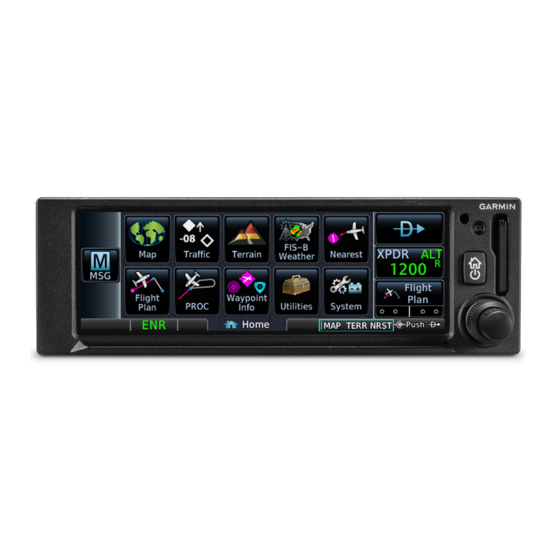
System at a Glance Overview GPS 175, GNC 355/355A, and GNX 375 are the first 2” by 6.25” panel mount navigators to employ full color capacitive touchscreen technology. GNC 355 shown as typical. GPS 175 is a TSO-C146e compliant GPS/WAAS navigator with en route, terminal, and precision/non-precision approach capabilities. -
Page 19: Unit Configurations
System at a Glance Unit Configurations GPS 175 GNC 355 GPS/MFD GPS/MFD/COM GNX 375 GPS/MFD/XPDR COMPARISON TABLE Mode S Dual-link 1090 ES Unit GPS/MFD Radio XPDR ADS-B In ADS-B Out • GPS 175 • • GNC 355 • • •... -
Page 20: Apps & Features
System at a Glance Apps & Features GPS 175 GNC 355/355A GNX 375 NAVIGATOR NAVIGATOR W/VHF NAVIGATOR COM TRANSCEIVER W/TRANSPONDER • • • Moving Map Moving Map Moving Map • • • Terrain Terrain Terrain • • • Flight Plan... -
Page 21: Pilot Interface
Powers the unit on or off and provides direct access to the Home page. Inner & Outer Knobs Multipurpose dual concentric knob allows data entry, list scrolling, map range control, page navigation, and COM volume and frequency tuning. COM is a function of GNC 355/355A only. 190-02488-01 Rev. B Pilot’s Guide... -
Page 22: Sd Card Slot
System at a Glance SD Card Slot NOTE Do not remove or insert an SD card while in flight. Always verify the system is powered off before inserting or removing an SD card. FEATURE REQUIREMENTS • SD card in the FAT32 format, with memory capacity between 8 GB and 32 GB The navigator requires an SD card for the following tasks. -
Page 23: Touchscreen
System at a Glance Touchscreen GESTURES Touching the screen briefly with a single finger. Use this gesture for: • Opening a page or menu • Activating a command key or data entry field • Displaying map feature information • Selecting an option within an application Certain momentary controls (e.g., directional arrow TAP AND HOLD keys) provide a secondary tap and hold function. -
Page 24: Keys
System at a Glance Keys COMMON COMMANDS Open the system messages Cancel an active function list. A flashing icon indicates without inputting data. unread messages. Open a context menu. Input a specified value. Return to the previous Select the corresponding page. -
Page 25: Menus
System at a Glance Menus Menus group related controls into an expandable pane, allowing access to multiple functions on a single page. Depending on the number of available functions, a menu may comprise more than one pane. Multiple panes are accessible by way of a left/right swipe or inner knob turn. -
Page 26: Tabs
System at a Glance Tabs Tabs group information into individual panes. Content includes scrolling lists, data fields, function keys, or a combination of controls. Tabs are located along the left and right sides of a pane. Active Tabs Inactive Tabs Inactive Tabs Keypads... -
Page 27: Control Knobs
Entering current or specified numerical value Inner Knob • Toggling Map user fields on or off (Push) • Accessing the Direct To function from the Home page GNC 355/355A • Selecting a page shortcut • Cursor placement and initial field/page selections • Outer Knob Moving cursor forward or backward within data field •... -
Page 28: Page Navigation Labels
System at a Glance Page Navigation Labels A locater bar works in conjunction with the outer knob, providing quick access to the indicated page. Turning the outer knob clockwise or counter-clockwise moves the locater through the available shortcut options. Active Page Slot 1 Slot 3 Slot 2... -
Page 29: Knob Shortcuts
System at a Glance GNC 355/GNC355A Knob focus defaults to page navigation when not in use. Map Active Flight Plan Active Available functions: Available functions: • • Map zoom Flight plan scrolling • • Set knob focus to standby Set knob focus to standby... - Page 30 System at a Glance GNC 355/355A From most pages: Pushing once enables standby frequency tuning mode and opens the COM volume controls. Turn the inner and outer knobs to tune the standby frequency. Pushing twice sets the knob focus to the volume slider. Turn the inner and outer knobs to adjust the volume percentage.
- Page 31 System at a Glance Screen Captures FEATURE REQUIREMENTS • SD card in the FAT32 format, with memory capacity between 8 GB and 32 GB FEATURE LIMITATIONS • Not available with Flight Stream 510 Save images to an SD card at any time using a screen capture. Images automatically save to the “print”...
-
Page 32: Color Conventions
System at a Glance Color Conventions • Warning conditions Yellow • Cautionary conditions Green • Safe operating conditions • Engaged modes • Active COM frequency White • Scales and markings • Current data and values • Heading legs Magenta • GPS data •... -
Page 33: Compatible Equipment
GMX 200 MX 20 OPTIONAL INTERFACES GDL 88/GTX 345 ADS-B transceiver (GPS 175 & GNC 355 only) ADC & AHRS AHRS units have a magnetometer interface for determining magnetic heading. ADC units have a Pitot-static interface for measuring pressure altitude. -
Page 34: Altitude Encoder
System at a Glance Altitude Encoder DISPLAY FUNCTION GAE 12 Provides pressure altitude Aircraft static pressure information to the transponder. ADS-B In Data DISPLAY FUNCTION Traffic Services • ADS-B • TIS-B Weather Services • FIS-B Weather Products Map & FIS-B Weather: •... -
Page 35: Get Started
Get Started 2 Get Started POWER UP ........................2-2 DATABASES.......................2-3 CONNECTIVITY....................2-14 COM........................... 2-18 XPDR ......................... 2-36 ADS-B ALTITUDE REPORTING..............2-43 PILOT SETTINGS....................2-46 STATUS INDICATIONS ..................2-56 LOGS.......................... 2-67 190-02488-01 Rev. B Pilot’s Guide... -
Page 36: Power Up
Tapping Continue advances to the Instrument Test page. If an instrument remains flagged after one minute, check the status of the associated LRU, then contact a Garmin dealer for support. Instrument Test To ensure safe operation, continuous built-in test features exercise the unit’s processor, memory, external inputs, and outputs. -
Page 37: Databases
Load databases via SD card. Once loading completes, you may power off the unit and remove the card. • Transfer databases from a Flight Stream 510 wireless datacard. This method requires the Garmin Pilot app on a portable electronic device. SUPPORTED DATABASES Bodies of water, geopolitical boundary, and road Basemap... -
Page 38: Database Effective Cycles
Get Started Database Effective Cycles Most databases expire at regular intervals. Exceptions include Basemap and Terrain, which neither expire nor update on a regular schedule. The start-up page lists all currently installed databases. Review this list for current database types, cycle numbers, and expiration dates. -
Page 39: Active And Standby Databases
Get Started Active and Standby Databases The navigator uses two types of databases: active and standby. Active databases are in use by the system. Standby databases have not reached the effective date. During normal operation, information about all active and standby databases are viewable on the associated info page. -
Page 40: Manual Updates
To open, tap the Databases key on the start-up page. DATABASE SOURCE INDICATION Connext Icon A Connext icon indicates when a database is from Garmin Pilot via wireless transfer. No indication means the database is either from an SD card or the unit’s internal standby queue. - Page 41 Get Started SELECT ALL DATABASES Select individual databases for transfer, or choose Select All if all listed databases require updating. After all selections are made, initiate the update process by tapping Start. By default, this page displays only the databases recommended for update.
- Page 42 Get Started ERROR INFORMATION To determine the cause of a database error, tap Error Info. An information window provides details regarding the state of the database. SELECT REGION This key appears when two databases are of the same type and cycle, but pertain to different regions.
-
Page 43: Automatic Updates
Get Started Automatic Updates When a newer database is available, Automatic updates occur follow the on-screen prompts to when: complete the update process. • A newer database is A status page displays a progress bar detected on the SD card or in and the name of each database as it uploads to the unit. -
Page 44: Database Concierge
Database Concierge allows wireless transfer of databases from a mobile device while the aircraft is on ground. A pilot selects and downloads databases inside the Garmin Pilot app. Transfers occur once Flight Stream 510 establishes a wireless connection inside the aircraft. Database Concierge Transfer Function •... - Page 45 Get Started Database Concierge transfers databases from the app to Flight Stream 510. A progress bar shows when this process is complete. Database Transfer Status The unit either updates or preloads databases based on their effective date. A second progress bar indicates upload status.
-
Page 46: Wi-Fi Setup
Flight Stream 510 requires power up. Wi-Fi is active, but the unit is waiting to connect with a device. Connection complete. Flight Stream 510 requires Garmin Pilot to be opened in order for database transfer to commence. Garmin Pilot opened and streaming to unit. -
Page 47: Database Sync
For information regarding database Receive only. Airport directory and chart packages, and individual database databases are not transmitted from purchases, visit flyGarmin.com. GPS 175, GNX 375, or GNC 355. ACTIVE AND STANDBY DATABASES Database SYNC transfer function includes active and standby databases. -
Page 48: Connectivity
AHRS data from built-in sensor GNX 375 only. GNX 375, or GPS 175 and GNC 355 with external ADS-B In source. Attitude data does not output to other installed avionics. The internal AHRS sensor is only for use with a portable electronic device. All internal AHRS functions are automatic and do not require pilot action. -
Page 49: Bluetooth Setup
Connext page. • AHRS • Magnetic heading • Flight plan transfer GNX 375, or GPS 175/GNC 355 with external ADS-B In source. Enabling Bluetooth Functionality Tapping Bluetooth Enabled toggles Bluetooth wireless functionality on or off. All associated setting controls and features are unavailable when this function is inactive. -
Page 50: Managing Paired Devices
Get Started Managing Paired Devices To view a list of all paired devices and their connection status, tap Paired Devices. To enable automatic connection between the unit and a paired device at power up, tap Auto Reconnect. AUTO RECONNECT Enables automatic connection between the unit and the paired device when the two are within range. -
Page 51: Importing A Flight Plan
Get Started Importing a Flight Plan This feature allows the automatic import of flight plans via Bluetooth wireless technology. It may be necessary to turn this function off if a portable device application makes repeated erroneous attempts to send flight plans to the unit. Once transfer is complete, an advisory message informs that a new flight plan is available for preview. -
Page 52: Com
Get Started AVAILABLE WITH: GNC 355/355A COM Standby Control Panel VHF COM transceiver controls are accessible via the selectable standby (STBY) frequency window. This control resides in the upper right corner of the display. Active Frequency Window Transfer (Flip-Flop) Key... -
Page 53: Com Volume Controls
Get Started COM Volume Controls Percent of Relative Volume Adjust radio volume according to Max Volume Indicator your preference. Directional keys allow volume adjustments. A cyan border indicates current knob focus. The unit retains volume settings over power cycles. Decrease Increase Volume Volume... - Page 54 Get Started OPEN SQUELCH Tap once to override the automatic squelch function. Tap again to return the squelch to automatic operation. “SQ” annunciates in the COM active frequency window to show when the squelch is overridden (i.e., when the squelch is open). The Open Squelch function is accessible from the COM Volume page and slide-out menu.
-
Page 55: Com Radio Setup
Get Started COM Radio Setup COM radio customization options reside in the Home System Setup app. System Setup Setup options for GNC 355A shown as typical. For COM radio selections, swipe to the end of the menu. From here you can: •... -
Page 56: Channel Spacing Option
AVAILABLE WITH: GNC 355A The GNC 355A supports channel tuning for both 8.33 kHz and 25 kHz channels within radio-frequency range. The GNC 355 supports frequency-channel pairings for 25 kHz channels only. Tapping this key toggles the transceiver channel spacing between 8.33 kHz and 25.0 kHz. -
Page 57: Reverse Frequency Look-Up
Get Started Reverse Frequency Look-up FEATURE REQUIREMENTS • Valid position data • Active navigation database FEATURE LIMITATIONS • Available only for the nearest stations in the database Display the facility identifier and frequency type for active and standby frequencies. The unit verifies the displayed frequency against the database at least once per minute. -
Page 58: Sidetone Volume Offset
Get Started Sidetone Volume Offset FEATURE LIMITATIONS • Availability dependent upon configuration • Offset range: +/-10% of total COM audio volume range Numeric Manual Offset If the unit is wired for audio Offset Value Indicator output, set the sidetone volume offset to the preferred level. -
Page 59: Tuning & Monitoring
Get Started Tuning & Monitoring Communication frequencies are split between two selectable windows: Active The upper window presents the active Frequency COM radio frequency. This is the frequency currently in use for transmit and Standby receive operations. Frequency The lower window presents the standby radio frequency. -
Page 60: Direct Tuning
Get Started Direct Tuning You may enter a standby frequency using the data entry keys on the COM Standby control panel or by pressing and turning the control knob. Tapping STBY opens the control panel. From here you may specify a frequency or select one using the provided search options. - Page 61 Get Started Attempting to enter a frequency value after selecting an invalid digit generates a pop-up message. Confirm the request by selecting OK. Simplified Frequency Entry The direct tuning field allows you the option of entering frequencies without typing the leading and/or trailing digits.
-
Page 62: Transfer Frequency To Active (Flip-Flop)
Get Started Transfer Frequency to Active (Flip-Flop) Before After The transfer (or flip-flop) function allows you to swap the active and standby frequency values. This function is accessible multiple ways. COM ACTIVE FREQUENCY WINDOW Tapping this window swaps the active frequency value with the standby frequency displayed in the lower window. -
Page 63: Monitor Mode
Get Started Frequency Autofill & Transfer If you initiate a transfer before completing frequency entry, the direct tuning field autofills the remaining characters, enters the frequency into the standby field, and then swaps it with the active frequency. Monitor Mode Enabling monitor mode allows you to listen to the standby frequency while the unit continues monitoring the active COM channel. -
Page 64: Frequency Selection
Get Started Frequency Selection The unit provides multiple options for finding and selecting a standby frequency from the available database frequencies. Search Tabs The Find key provides access to multiple search tabs. Each tab displays a list of selectable identifiers based on specific criteria. Nearest •... - Page 65 Get Started TAB ENTRIES Waypoint Bearing & Identifier Distance Each entry includes general information about the associated waypoint. Frequency Key MULTIPLE FREQUENCIES This key appears when more than one frequency is available at the indicated identifier. Applicable to functions displaying information only (Nearest Airports, FSS, and ARTCC).
-
Page 66: Remote Frequency Selection
Get Started Remote Frequency Selection FEATURE LIMITATIONS • Availability dependent upon configuration On units configured for remote frequency recall, user frequencies are selectable via a remote switch. • Pressing the switch once loads the next user frequency into the STBY window •... -
Page 67: Create User Frequencies
Get Started Create User Frequencies FEATURE LIMITATIONS • Names may be up to seven characters in length • Maximum number of 15 user frequencies Create or edit user frequencies from the Edit Frequency Edit Frequency pop-up menu. Name Type name Frequency Specify Frequency Save Delete •... - Page 68 Get Started ADD A USER FREQUENCY From the COM Standby page: 1. Tap Find > Select the User tab. 2. Tap Add User Frequency. 3. Specify the frequency name and value. 4. Tap Save. A pop-up message informs when the user frequency list is full. EDIT USER FREQUENCY Tapping the Edit key for an existing entry opens the same pop-up.
-
Page 69: Com Alert
If a failure occurs while the control page is active, the display automatically returns to the previous page. UNIT CONDITION GNC 355 Invalid COM radio data. GNC 355A For information regarding pilot response to a COM radio failure, consult the AFMS. -
Page 70: Xpdr
Get Started XPDR AVAILABLE WITH: GNX 375 XPDR Control Panel Transponder controls are accessible via the XPDR key. This key is unavailable when the control panel is active. Squawk Code Entry Field Squawk Code Entry Keys VFR Key Data Field XPDR Mode Key The XPDR key becomes available when you:... -
Page 71: Xpdr Setup
Get Started XPDR Setup Tap Menu to access the transponder setup XPDR Menu options. From here you can: Data Field • Change the display of data PRESS ALT • Enable 1090 ES ADS-B Out FLT ID functionality (if configured) ADS‐B Out • Assign a unique flight ID Flight ID Specify flight ID (if configurable) -
Page 72: Enabling Extended Squitter Transmissions
Get Started Enabling Extended Squitter Transmissions Tapping ADS-B Out allows the transmission of ADS-B Out messages and position information. Assigning a Flight ID FEATURE LIMITATIONS • Availability dependent on configuration If the flight ID is editable, tap Flight ID and assign a unique identifier. Flight IDs are alphanumeric (upper-case only) and have an eight character limit. -
Page 73: Xpdr Modes
Get Started XPDR Modes Tapping Mode opens a menu of the available transponder modes. Options include Standby, On, and Altitude Reporting. MODE FUNCTION • Transponder does not reply to interrogations or transmit ADS-B Out • Standby Bluetooth wireless functions remain operational •... -
Page 74: Squawk Code Keys
Get Started Squawk Code Keys Eight squawk code entry keys (0 – 7) SPECIAL SQUAWK CODES provide access to all ATCRBS codes. 1200 Default VFR code (USA) Tapping one of these keys begins the code selection sequence. 7500 Hijacking Use the Backspace key or outer 7600 Loss of communications control knob to move the cursor. - Page 75 Get Started TRANSPONDER STATUS INDICATIONS IDENT Standby Mode • • Reply active Standby mode • • IDENT function active Current squawk code (inactive) • No change to transponder code IDENT with New Squawk Code Altitude Reporting Mode • • Reply active Altitude reporting mode •...
-
Page 76: Remote Control
Get Started Remote Control Transponder functions are controllable from a connected G3X Touch display. Control features include: • • Squawk code Transponder mode • • IDENT ADS-B transmission • Flight ID For transponder control operation, consult the G3X Touch Pilot’s Guide. XPDR Alert If the transponder fails: •... -
Page 77: Ads-B Altitude Reporting
ADS-B Out controls are accessible via the ADS-B key. The location of this key varies by unit type. On GPS 175, it resides in the upper right corner of the display. On GNC 355, it resides on the GDL 88 Status page. Altitude Reporting Status Flight ID Key... -
Page 78: Ads-B Key
Get Started ADS-B Key FEATURE LIMITATIONS • Functionality dependent upon GDL 88 configuration Active Transponder Depending on the configuration Transponder Mode (ALT) of your GDL 88, tapping the ADS-B key: • Reports GDL 88 altitude reporting status Squawk Code (as reported by GDL 88) •... -
Page 79: Assigning A Flight Id
UNIT CONDITION GPS 175 GDL 88 failure. GNC 355 For information regarding pilot response to ADS-B failures, consult the AFMS. 190-02488-01 Rev. B Pilot’s Guide 2-45... -
Page 80: Pilot Settings
Connext Paired Devices Setup options, refer to the Bluetooth Enabled respective section. Flight Plan Import GNC 355/355A only. GNC 355A only. CDI Scale Set the scale for the course deviation indicator. Scale Home values represent full scale deflection for the CDI to either side. -
Page 81: Horizontal Alarm Limits
Get Started CDI scale is set to “Auto” (default). At the default setting, the scale sets to 2.0 nm during the en route phase of flight. Aircraft is within 31 nm of the destination airport (i.e., terminal area). The scale linearly ramps down to 1.0 nm over a distance of 1 nm. Aircraft is leaving the departure airport. -
Page 82: Cdi On Screen
Get Started CDI On Screen AVAILABLE WITH: GPS 175 | GNX 375 Toggling this setting displays the CDI scale on screen. When active, a CDI with lateral deviation indicator displays below the GPS NAV Status Indicator key. CDI OFF CDI ON Only the Flight Plan page The CDI provides no indications access key is available. -
Page 83: Airport Runway Criteria
Get Started Airport Runway Criteria Specify runway criteria from the System Setup app. Home Selections determine which airports are suitable when using the nearest airport search feature. System Setup During an approach, the terrain alerting algorithm uses airport runway settings to avoid nuisance alerts. Runway Surface Tap Runway Surface and then select Runway Surface Options... -
Page 84: Clocks & Timers
Get Started Clocks & Timers Timers Monitor time in flight using three available timer types. Timer settings are accessible via the Utilities menu Home page. Toggle between timer types using the provided display key. Utilities Clock/Timers Clock/Generic Timer Trip/Departure Timers Stopwatch style counter. -
Page 85: Page Shortcuts
Get Started Page Shortcuts A knob shortcut option allows you to customize slots 2 and 3 of the locater bar. Slot one is reserved for the Map page. Tap a slot key and assign a page to that slot. Depending on configuration, Traffic Page Shortcut Options and Weather shortcuts may not be •... -
Page 86: Alerts Settings
Get Started Alerts Settings Airspace alerts generate a message. They rely on three-dimensional data (altitude, latitude, and longitude) to avoid nuisance alerts. FEATURE LIMITATIONS • Alert altitudes are dependent on aircraft and airspace altitudes and the pilot-specified altitude buffer value Control keys allow you to select which airspace boundaries generate an alert annunciation upon entry. -
Page 87: Unit Selections
Get Started Unit Selections Customize the display unit settings. Tapping a parameter key opens a menu of the available unit types. PARAMETER SETTINGS • Nautical Miles (nm/kt) Distance/Speed • Statute Miles (sm/mph) • Celsius (ºC) Temperature • Fahrenheit (ºF) • Magnetic (º) •... -
Page 88: Display Brightness Control
Installer configured curves determine the amount of change in brightness that occurs in response to a control adjustment. If brightness control is not satisfactory, contact a Garmin dealer to adjust the lighting curves. 2-54 Pilot’s Guide 190-02488-01 Rev. B... -
Page 89: Scheduled Messages
Get Started Scheduled Messages Create custom reminder messages and set when they will display. Allows one time, periodic, and event-based message types. Active reminders appear at the top of Home the scheduled message list. This list is accessible via the Utilities menu page. Utilities Scheduled Messages Examples: •... -
Page 90: Status Indications
Get Started Status Indications Alert Types The unit generates annunciations in response to various conditions that may occur. These abbreviated messages are grouped according to the level of urgency and required response. They display in order of priority, from highest to lowest. 1. -
Page 91: Alert Annunciations
Get Started Alert Annunciations Alert annunciations are abbreviated messages that indicate an alerted function or mode. The color of the annunciation depends on the alert type. • Warnings display in white text on red ALERT COLORS background WARNING • Cautions display in black text on amber CAUTION background ADVISORY... -
Page 92: Pop-Up Alerts
Get Started Pop-up Alerts If a warning or caution relating to terrain or traffic occurs, a pop-up window may display. These pop-ups only appear if the alerted function’s associated page is not active. Each pop-up alert provides: Pop-up Alert Priority •... -
Page 93: Aural Alerts
A Mute Alert key allows you silence the active traffic alert voice message. GPS 175/GNC 355 systems interfaced to a traffic system (GDL 88 or GTX 345): Aural alerts are available. They are provided directly from the traffic system LRU to the audio panel. -
Page 94: System Status
• GPS/WAAS software version For more about active and standby • COM board software version databases, refer to Databases. (GNC 355/355A only) • Transponder software version (GNX 375 only) GPS Status Monitor GPS receiver performance, establish a baseline for normal system operation, and troubleshoot weak or missing signal issues. - Page 95 Get Started SIGNAL STRENGTH INDICATIONS A graph shows GPS signal strength for Satellite SVIDs up to 15 satellites. As the GPS receiver Each bar is labeled with the SVID locks onto satellites, a signal strength bar of the corresponding satellite. appears for each satellite in view.
-
Page 96: Circle Of Uncertainty
Under 14 CFR parts 91, 121, 125, and 135, the FDE availability prediction program must be used prior to all oceanic or remote area flights using GPS 175/GNX 375/GNC 355 as a primary means of navigation. Circle of Uncertainty FEATURE LIMITATIONS •... -
Page 97: Sbas Providers
Get Started SBAS Providers NOTE Operating with SBAS active outside of the service area may cause elevated EPU values to display on the status page. Regardless of the EPU value displayed, the LOI annunciation is the controlling indication for determining the integrity of the GPS navigation solution. -
Page 98: Gps Alerts
Get Started GPS Alerts The following alert conditions can affect GPS accuracy. INDICATIONS FAULT TYPE CONDITION Integrity of the GPS position does not meet the requirements for the Yellow “LOI” Loss of Integrity current phase of flight. Occurs annunciation. before the final approach fix (if an approach is active). -
Page 99: Ads-B Status
Get Started ADS-B Status FEATURE REQUIREMENTS • GDL 88 or GTX 345 ADS-B transceiver (GPS 175 and GNC 355/355A only) • GNX 375 STATUS PAGE ACCESS KEY Tap this key to view last uplink time and GPS source information. GPS 175/GNC 355/355A: Key label reflects the configured ADS-B source. - Page 100 Get Started FIS-B WX STATUS Tap this key to view the status of FIS-B weather products. This page is also accessible from the FIS-B Weather setup menu. TRAFFIC APPLICATION STATUS Tap this key to view the status of the three traffic applications: •...
-
Page 101: Logs
Get Started Logs Export to SD Card A logging function stores WAAS diagnostic and ADS-B traffic data (GNX 375 only) in the unit’s internal memory. This information is available for export to an SD card for later analysis. FEATURE REQUIREMENTS •... - Page 102 INTENTIONALLY LEFT BLANK 2-68 Pilot’s Guide 190-02488-01 Rev. B...
-
Page 103: Navigation
Navigation 3 Navigation MAP..........................3-3 ACTIVE FLIGHT PLAN..................3-27 DIRECT TO......................3-43 WAYPOINTS......................3-49 PROCEDURES....................... 3-64 190-02488-01 Rev. B Pilot’s Guide... - Page 104 Navigation NAVIGATION APPS & FUNCTIONS Menu selections vary based on features and optional equipment installed with Garmin avionics. Catalog Airport Orientation North Up Above Preview Intersection Visual APPR Store Configure User Fields Delete Restore User Fields Parallel Track Map Detail Invert User WPT TOPO Edit Data Create Fields Terrain Traffic NEXRAD...
-
Page 105: Map
• UAT receiver (FIS-B weather) FEATURE LIMITATIONS NEXRAD, Lightning, and Terrain overlay functions are mutually exclusive. Enabling one automatically disables the other. GNC 355 shown as typical. Default Map Features Aircraft Symbol Depicts current aircraft position and orientation. • Tip represents actual aircraft location •... - Page 106 Default user fields are as follows. GPS 175/GNX 375: • distance • ground speed • desired track and track • distance/bearing from destination airport GNC 355/355A: • distance • ground speed • desired track and track • from, to, and next waypoints NAV Range Ring Displays current direction of travel on a rotating compass.
- Page 107 Navigation LAND AND WATER DEPICTIONS Land and water data are for general reference only. Data accuracy is not suitable for use as a primary navigation source. The information is intended to supplement and not replace official government charts and notices. DATA DRAWING ORDER The electronic map draws data in order of priority, from highest (1) to lowest (25), with higher priority features drawn atop those of lower priority.
-
Page 108: Map Setup
Navigation Map Setup Map setup options allow you to customize Map Menu the display of aeronautical information. Tap Menu when you need to: Orientation • Change map orientation settings North Up • Configure user fields Track Up Heading Up • Adjust the map detail level North Up Above •... -
Page 109: Configure User Fields
Map and the Active FPL page. They reappear in their respective corners when you return to the Home page or use the knob to move between Map and any other application.* * This functionality is not available on GNC 355/355A. 190-02488-01 Rev. B Pilot’s Guide... - Page 110 Generic Timer display Do not display data field Timer GPS ground speed GNC 355/355A only. “Destination” refers to the missed approach point (if an approach is loaded) or the final airport in the flight plan. Pilot’s Guide 190-02488-01 Rev. B...
-
Page 111: Map Orientation
Navigation Map Orientation Sets the orientation of the map display. Options include North Up, Track Up, or Heading Up. Label below the North indicator shows the current orientation. This label is absent when the info banner is active. North Up is useful when zoomed out to view the entire route or a frontal system on a NEXRAD display. -
Page 112: Visual Approach
Navigation Visual Approach Sets the distance from the destination airport at which the Visual Approach selector key becomes active. Visual Approach To reduce page clutter, the key moves to the upper left corner of the display when the info banner is active. -
Page 113: Track Vector
Navigation Track Vector FEATURE LIMITATIONS • Indication absent when aircraft velocity is < 30 kt Indicates the current ground track. Arrow tip represents aircraft position at the specified time interval (if the aircraft maintains current ground track during that time). Track vector length options display as a dashed line and arrow extending from the aircraft icon, showing current track and distance the aircraft will travel in the selected time. -
Page 114: Map Detail
Navigation Map Detail Changes to the map detail level take effect immediately. Options include full, high, medium, and low. FEATURE FULL HIGH MEDIUM • Small Cities • Medium Cities • Large Cities • Freeways • Highways • Roads • Railroads •... - Page 115 Navigation AVIATION DATA SYMBOLS Non-towered, Non-towered, serviced non-serviced airport airport Towered, non-serviced Towered, serviced airport airport Soft surface, non-serviced Soft surface, serviced airport airport Restricted (private) airport Unknown airport Heliport ILS/DME or DME only Intersection TACAN VOR/DME VORTAC Runway extension [1] Symbol depicts orientation of longest runway.
-
Page 116: Map Interactions
Navigation Map Interactions Basic Interactions Typical map interactions include zoom, pan, and object selection. PAN & ZOOM Panning allows movement of the map in any direction without change to the current zoom setting. Zooming adjusts the current magnification level between pre-defined range parameters. - Page 117 Navigation MAP INFO Selected Airport Available information and controls are dependent upon object or location type and proximity to other objects. Selecting an airport icon displays the airport’s highest field elevation. A map pointer icon corresponds with the touch point on the map. An information page access key displays when you select a waypoint, airspace, airport, airport surface hot spot, or TFR.
-
Page 118: Graphical Flight Plan Editing
Navigation AIRSPACE INFO Selected Airspace When selected, active airspace boundaries change color. Tapping Airspace Info opens the associated information page. Data fields display information specific to the selected airspace. Available controls reside along the bottom of the page. Info Controls •... - Page 119 Navigation TEMPORARY FLIGHT PLAN BANNER An information banner displays waypoint selections made during graphical edit mode. All selections become active once you tap Done. Lists up to four waypoint identifiers Ellipse indicates additional waypoints Initial waypoint in flight plan always appears first Tapping Undo reverses the last edit.
- Page 120 GPS 175 & GNX 375: Active route identifiers also appear on the GPS NAV Status indicator key in the lower right corner of the display. GNC 355/355A: If configured, a user field shows active route identifiers on Map. Delete any existing flight plan before attempting to graphically edit a direct-to waypoint.
- Page 121 Navigation REMOVE WAYPOINT FROM FLIGHT PLAN You can tap and drag any leg to another waypoint or airway, or release it away from any waypoint if an alternate destination is not preferred. CREATE LEGS WITHOUT AN EXISTING FLIGHT PLAN If an active flight plan does not exist, you can graphically create one without ever leaving the Map page.
-
Page 122: Map Overlays
• METAR Weather product and traffic overlays • Lightning are optional on GPS 175 and GNC 355. They are available only when configured for ADS-B In equipment. Overlay Controls Control keys enable the specified overlay function only and do not activate interfaced equipment. Control keys remain active even in the absence of required data. - Page 123 TRAFFIC • Overlays traffic information • Filter selection on the Traffic page determines altitude range • Feature optional for GPS 175 and GNC 355 NEXRAD • Overlays datalink precipitation weather information • Options include: CONUS, Regional, or off (none) •...
- Page 124 Navigation • Overlays graphical TFRs • Tapping this airspace symbol displays details regarding the restricted area • Feature optional for GPS 175 and GNC 355 AIRSPACES • Overlays airspace boundaries with altitude labels • Filter selection determines altitude range AIRWAYS •...
-
Page 125: Overlay Status Icons
Navigation Overlay Status Icons Icons indicate which overlays are present at the current map range. The absence of an overlay icon means one of two possible conditions: 1. Overlay not present at the current detail level or zoom setting. 2. Overlay control is off. METAR NEXRAD Obstacle... -
Page 126: Smart Airspace
Navigation Smart Airspace Garmin’s Smart Airspace feature automatically de-emphasizes non-pertinent airspace away from the aircraft’s current altitude. When an airspace’s vertical proximity to the aircraft is >1,000 ft: Smart Airspace Off • Its boundary becomes transparent Non-pertinent Airspace • All associated altitude labels... -
Page 127: Safetaxi
Navigation SafeTaxi SafeTaxi provides greater map detail and higher image resolution at lower zoom levels. Feature labels denote: • Runways • Taxiways • Airport landmarks SafeTaxi Features • Airport diagram overlay that includes hot spot information • Aircraft position relative to taxiways, runways, and airport landmarks •... - Page 128 Navigation HOT SPOTS SafeTaxi hot spots identify locations on an airport surface where positional confusion or runway incursions are likely to occur. These known problem areas require heightened attention by pilots. Selecting the border of a hot spot displays a brief summary of the indicated hazard and an information key.
-
Page 129: Active Flight Plan
Navigation Active Flight Plan Current flight plan information displays as a scrolling list on the Active Flight Plan (FPL) page. FEATURE REQUIREMENTS • Active flight plan FEATURE LIMITATIONS • Displays up to 100 waypoints for an active flight plan Active Flight Plan Page Selectable Data Field Columns Add Waypoint Key Waypoint Identifier Column... - Page 130 Navigation AIRPORT INFO Procedure Airport Info For convenience, airport Header information is directly accessible from the procedure header. This includes airports specified in active approaches, arrivals, and departures. Tap Airport Info to open the corresponding information page. FIX TYPE INDICATIONS When applicable, labels indicate LABEL FIX TYPE...
- Page 131 MAHP Active Leg Arrow Parallel Track Direct To Arc Right GNC 355/355A: Activating a direct-to course displays the corresponding fix symbol and waypoint identifier in two locations: Map User Field Active Direct To Fix Indicator If configured, a user field shows...
-
Page 132: Collapse All Airways
Navigation Collapse All Airways Airways automatically display as flight plan legs. A single airway may contain numerous legs. Airways without an active leg collapse for simplification. This does not affect airway legs shown on the external navigator(s). All airways begin with Airway Indication an indicator field and end with an exit... -
Page 133: Obs
Navigation The Omni Bearing Selector (OBS) allows you to select between manual or automatic sequencing of waypoints. When active, this function allows you to set the desired course To/From a waypoint using the provided controls or with an external OBS selector on HSI or CDI. 1. -
Page 134: Dead Reckoning
Navigation Dead Reckoning WARNING Do not use projected position data as the only means of navigation. Points About Dead Reckoning • Provides limited navigation using the last known position and speed following the loss of GPS navigation while on an active flight plan •... -
Page 135: Parallel Track
GPS 175 & GNX 375: Active route identifiers also appear on the GPS NAV Status indicator key in the lower right corner of the display. GNC 355/355A: If configured, a user field shows active route identifiers on Map. 190-02488-01 Rev. B Pilot’s Guide... - Page 136 Navigation Offset Offset Distance From Offset From ACTIVATE A PARALLEL TRACK 1. Tap Menu > Parallel Track. 2. Tap Offset and specify a distance between 1 nm and 99 nm. 3. Tap Direction and select left of track or right of track. 4.
-
Page 137: Edit Data Fields
Navigation Edit Data Fields To select a flight plan data column, tap Edit Data Fields. Columns are arranged in numerical order (1 - 3). To restore columns to default display settings, tap Restore Defaults. Selections are identical for each column. DATA FIELD SELECTIONS By default, flight plan information fields display:... -
Page 138: Catalog Route Options
Navigation Catalog Route Options Selecting a flight plan opens a menu. Changes to Route Options the active flight plan take effect immediately. Activate • Activate the selected flight plan Invert & Activate (replacing the active flight plan) Preview • Reverse and activate the selected flight plan Edit •... - Page 139 Navigation DELETE A FLIGHT PLAN Deleting the active flight plan does not delete the stored flight plan in the catalog. From the FPL menu: 1. Tap Menu > Delete. 2. Confirm the request. From the catalog: 1. Select a flight plan. 2.
-
Page 140: Create A Flight Plan
Navigation Create a Flight Plan NOTE The unit cannot verify the accuracy of cataloged flight plans with modified procedures. There are three methods for creating a new flight plan. CREATE FROM THE ACTIVE FLIGHT PLAN PAGE 1. Tap Flight Plan. 2. -
Page 141: Flight Plan Waypoint Options
Navigation Flight Plan Waypoint Options Selecting a waypoint identifier opens a menu. Options Menu Changes to the active flight plan take effect immediately. Insert Before Insert After • Insert a new waypoint into a flight plan Load PROC • Add an airway or procedure Load Airway •... -
Page 142: Flight Plan Map Overlays
Navigation Flight Plan Map Overlays Leg Status Indications Active, next, and previous flight plan legs LEG STATUS COLOR overlay on the Map page and are display Active Magenta only. Next & Future White Past or Inactive Gray Previous Leg(s) Active Leg Next Leg(s) Leg Status Indications 3-40... -
Page 143: Flight Plan User Field
Navigation Flight Plan User Field AVAILABLE WITH: GNC 355/355A FEATURE REQUIREMENTS • Active flight plan for from-to-next route information If configured, a user field shows active route identifiers (from-to-next) on Map. From, To, and Next Identifiers Map User Fields No Flight Plan Exists... -
Page 144: Gps Nav Status Key
Navigation GPS NAV Status Key AVAILABLE WITH: GPS 175 | GNX 375 Located in the lower right corner of the display, the GPS NAV Status indicator key displays from-to-next route information when an active flight plan exists. Indications change based on active leg status. No Flight Plan Exists Route Indicator Only Tap for direct access to the... -
Page 145: Direct To
Navigation Direct To Tapping this key opens the Direct To function. Search tabs provide three different methods of waypoint selection. FEATURE LIMITATIONS • Not all flight plan entries are selectable using Direct To (e.g., holds, course reversals) Direct To Basics Set a course to any waypoint using Direct To is useful for Direct To. - Page 146 Navigation WAYPOINT Similar to an information page, but with course and hold options. This tab is active by default. Info Controls • • Distance and bearing from current Waypoint Identifier key with aircraft position access to multiple search tabs • •...
-
Page 147: Direct To Activation
GPS 175 & GNX 375 GNC 355/355A GPS NAV Status key changes Direct To key changes to show to show active leg status. the active direct-to fix. Indication includes the corresponding fix symbol and waypoint identifier. -
Page 148: Navigating Direct To
Navigation Navigating Direct To While most direct-to operations follow the same basic steps, the method for selecting a waypoint may vary. DIRECT TO A NEW WAYPOINT 1. Tap Direct To. 2. Select a waypoint identifier. 3. Tap Course and specify the course heading (if a specific course is necessary). 4. -
Page 149: Removing A Direct-To Course
Navigation DIRECT TO AN OFF-ROUTE COURSE You may activate an off-route course using any of the described direct-to methods. Activating an off-route direct-to course automatically deactivates the current leg of the active flight plan. Direct To & Procedure Fixes Approach guidance is not available for procedure fixes. -
Page 150: User Holds
Navigation User Holds You may define a holding pattern for any direct to waypoint. User holds suspend automatic waypoint sequencing until they expire or are removed. Tapping Hold displays available hold options. GPS 175 shown as typical. Accept the specified hold parameters and return to the Load Hold Direct To window. -
Page 151: Waypoints
Navigation Waypoints There are two types of waypoints: database and user Database waypoints (i.e., waypoints contained in the navigation database) are organized into the following groups. • Airport (APT) • Intersection (INT) • Very High Frequency Omni-directional Range (VOR) • Visual Reporting Point (VRP) •... - Page 152 Navigation Intersection, VOR, VRP, and NDB information pages have a uniform layout. VOR Information Page Waypoint Identifier key Nearest NAVAID information Location Information Waypoint coordinates Preview key Waypoint distance and bearing Waypoint specific information (e.g., class, station declination, frequency) COMMON PAGE FEATURES All waypoint information pages share the following features.
- Page 153 Navigation WAYPOINT SPECIFIC PAGE FEATURES Features listed here are unique to the corresponding waypoint. Airport Selectable abs: Info: Airport location, elevation, time zone, and fuel availability. Procedures: Available approach procedures. Runways: Identifiers, size, surface type, and traffic pattern direction. Tapping Runway opens a list of available runways.
- Page 154 Navigation User Waypoint Selectable functions: Edit: Opens the Create User Waypoint page for editing purposes. View List: Displays a list of all user waypoint identifiers. Delete: Removes the selected user waypoint from the list. Delete All: Removes all user waypoints from the list. All deletions require user confirmation.
-
Page 155: Waypoint Selection
Navigation Waypoint Selection The Waypoint Identifier key provides access to different waypoint search options. Enter a specific identifier or select one from the available search tabs. FastFind Predictive Waypoint Entry FastFind predicts a waypoint based on the characters you select. As you type, the key label changes to reflect the identifier of the nearest matching entry. -
Page 156: Search Tabs
Navigation Search Tabs The Find key provides access to multiple search tabs. Each tab displays a list of selectable identifiers based on specific criteria. Waypoint Search Tabs Waypoint Type Icon Identifier Each entry includes general information about the associated waypoint. Bearing &... - Page 157 Navigation USER Lists up to 1,000 user-defined waypoints. SEARCH BY NAME Lists all airports, NDBs, and VORs associated with the specified facility name. Tap Search Facility Name to begin search. SEARCH BY CITY Lists all airports, NDBs, and VORs found in proximity of the city.
-
Page 158: Create User Waypoints
Navigation Create User Waypoints Create and store up to 1,000 user defined waypoints. FEATURE LIMITATIONS • Duplicate user waypoint identifiers are not allowed • Names may be up to six characters in length • Comment may be up to 25 characters •... -
Page 159: Define Waypoint Criteria
Navigation Define Waypoint Criteria Active user waypoints already existing in a Create Waypoint flight plan are not editable. User Identifier When creating a user waypoint, you have Specify identifier the option to: Comment • Create a user waypoint Type comment • Assign a unique identifier Position •... - Page 160 Navigation COMMENT FORMAT Default comments display in a specific format for each reference type. LAT/LON Radial/Distance <LAT> <LON> <Waypoint><Radial> / <Distance> Radial/Radial <Waypoint 1><Radial 1> / <Waypoint 2><Radial 2> POSITION OPTIONS Set the Waypoint Position using one of the following options. Radial/Radial: Specify a waypoint and radial for each of the two reference points.
-
Page 161: Edit An Existing User Waypoint
Navigation Edit an Existing User Waypoint FEATURE LIMITATIONS • User waypoints that are part of a flight plan are not editable OPEN EDIT WAYPOINT PAGE You can access the edit function multiple ways. From the dedicated information page: Home > Waypoint Info > User WPT > Specify an identifier, or tap View List and select an identifier from the used waypoints list >... -
Page 162: Import User Waypoints
Navigation Import User Waypoints The Import Waypoints key appears when the unit detects a user waypoint on the datacard. FEATURE LIMITATIONS • User waypoint file size must not exceed 8 GB NOTE The import function overwrites any existing user waypoint of the same name. CREATE USER WAYPOINT FILE You may create a list of new user waypoints using any spreadsheet program. - Page 163 Navigation User Waypoint File Considerations • Limit one waypoint per row • Names may be up to six characters in length • Comments may be up to 25 characters • All letters must be upper case • Latitude: two digits left of decimal; up to nine digits right of decimal •...
-
Page 164: Nearest
Navigation Nearest View a list of the nearest waypoints, frequencies, or facilities within 200 nm of the aircraft’s position. From the Home page: 1. Tap Nearest > Select a waypoint or frequency icon. 2. Scroll through the list of entries. Information varies according to the selected waypoint or frequency type. - Page 165 Navigation Nearest Airspace • Identifier • symbol • proximity Nearest Air Route Traffic Control Center • Facility name • distance • bearing • frequency Nearest Flight Service Station • Facility name • distance • bearing • frequency (“RX” denotes receive-only frequencies) Nearest Weather Frequency •...
-
Page 166: Procedures
Navigation Procedures Lateral and vertical guidance is available for visual and GPS/RNAV approaches. The published instrument approach procedures allow precision and non-precision approaches to airports and are directly accessible from the Procedures (PROC) icon. FEATURE REQUIREMENTS • Baro-corrected altitude source (automatic sequencing of altitude leg types) In the absence of baro-corrected altitude data, altitude leg types require manual sequencing. -
Page 167: Flight Procedure Basics
Navigation Flight Procedure Basics NOTE Advisory climb altitudes for SIDs may not match charted altitudes. Do not rely solely on advisory altitudes. • Always check the runway, transition, and waypoints for all procedures. • Heading legs indicate in white as “HDG XXXº” on flight plans. •... - Page 168 Navigation Roll Steering Autopilots Roll steering terminates when approach mode is selected on the autopilot. It becomes available once you initiate the missed approach. TO/FROM LEGS ON CDI TO Legs FROM Legs On these legs, the FROM/TO flag on On these legs, the FROM/TO flag on the CDI indicates “TO”...
-
Page 169: Gps Flight Phase Annunciations
Navigation GPS Flight Phase Annunciations Flight Phase Check the annunciator bar for current phase (Caution) of flight. Under normal conditions, these annunciations are green. They turn yellow when cautionary conditions exist. Phase of flight annunciations are a direct indication of the current CDI behavior for the selected navigation source. - Page 170 Navigation ANNUNCIATION FLIGHT PHASE Localizer Performance Approach • Fly to published LP minimums Localizer Performance Approach with Advisory Vertical Guidance LP +V • Fly to published LP minimums Localizer Performance with Vertical Guidance Approach • Fly to LPV minimums Missed Approach •...
-
Page 171: Departures
Navigation Departures Loading a Departure into Flight Plan • Always load the departure at the departure airport in the flight plan • Flight plans allow only one departure procedure at a time • Loading a departure when one is already present will replace the existing entry •... -
Page 172: Flight Plan Departure Options
Navigation Flight Plan Departure Options Selecting a departure on the flight plan opens Departure Options a menu. Changes to the active flight plan take effect immediately. Select Departure Remove Departure • Select a new departure • Remove the selected departure from the flight plan 3-70 Pilot’s Guide 190-02488-01 Rev. -
Page 173: Arrivals
Navigation Arrivals Loading an Arrival into Flight Plan • Load a Standard Terminal Arrival (STAR) at any airport with a published arrival procedure • Flight plans allow only one arrival procedure at a time • Loading an arrival when one is already present will replace the existing entry •... -
Page 174: Flight Plan Arrival Options
Navigation Flight Plan Arrival Options Selecting an arrival on the flight plan opens a menu. Arrival Options Changes to the active flight plan take effect immediately. Select Arrival Remove Arrival • Select a new arrival • Remove the selected arrival from the flight plan 3-72 Pilot’s Guide 190-02488-01 Rev. -
Page 175: Approaches
Navigation Approaches Loading an Approach into Flight Plan • Always check the runway, transition, and all waypoints • Flight plans allow only one approach procedure at a time • You may load an alternate approach during a missed approach procedure (flight plan retains all missed approaches) •... - Page 176 Navigation To change or remove the approach: • Tap the existing flight plan approach. • Select a different one. • Tap Remove Approach. SBAS APPROACHES To load an SBAS approach: Channel ID Key 1. Tap Channel/ID. • Select the channel ID for an 2.
-
Page 177: Flight Plan Approach Options
Navigation PROCEDURE TURNS A procedure turn is stored as another Roll Steering & approach leg. It does not require any Procedure Turns special operations other than flying the procedure itself. The steering provided for a procedure turn does not guarantee Roll steering is available for aircraft that the aircraft will with a compatible autopilot. -
Page 178: Missed Approach
Navigation Missed Approach The method for activating a missed approach depends on your position in relation to the missed approach point. BEFORE MISSED APPROACH POINT Select Activate Missed Approach. This function is available in two applications: Active FPL: Home > Flight Plan > Select the approach > Activate Missed Approach Procedures: Home >... -
Page 179: Approach Hold
Navigation Approach Hold Selecting an approach hold on the flight plan opens a Hold Options menu. Changes to the active flight plan take effect immediately. Activate Hold Insert After • Activate the selected hold Edit Hold • Insert a waypoint after the hold Exit Hold •... - Page 180 Navigation NON-REQUIRED HOLDING PATTERNS Upon activating an RNP GPS approach, decide whether to skip non-required holding patterns during the initial transitions of the approach. A pop-up presents two options. Selecting Yes adds the hold to the flight plan. Preview shows the hold in white. Selecting No means the hold is not included in the flight plan.
-
Page 181: Dme Arc
Navigation DME Arc The unit supports approaches DME Arc Approaches containing DME arcs. • Left/right guidance relative to To manually activate DME Arc, the the arc aircraft must be within the shaded area. • Manual arc leg activation once aircraft is near the arc DME Arc Intermediate Initial... -
Page 182: Rf Legs
Navigation RF Legs The unit supports radius-to-fix (RF) AC 90-101A - RF Legs legs associated with RNAV RNP 1.0 AC 90-101A defines RF leg as non-AR approaches, when approved by “A constant radius circular path, the installation. around a defined turn center, that Flying a radius-to-fix approach is similar starts and terminates at a fix. -
Page 183: Ils Approach
Navigation ILS Approach NOTE ILS and LOC approaches are not approved for GPS. GPS guidance is for monitoring purposes only. Selecting an ILS or LOC approach results in a pop-up message. Activate the approach or select a different one. Do not attempt to use the unit as the primary navigation source during ILS approach. -
Page 184: Rnav Approaches
Navigation RNAV Approaches Fly RNAV approaches according to the published chart. Supported approaches include: • • • LNAV/VNAV LNAV+V • • • LNAV LP+V LNAV APPROACH RNAV non-precision lateral navigation approach. LNAV+V APPROACH RNAV non-precision LNAV approach with advisory vertical guidance. The glidepath is a light dashed line on the vertical profile (Jeppesen charts only) with an associated glidepath angle (usually in the 3.00 degree range) to assist in maintaining a constant vertical glidepath, similar to an ILS glideslope. - Page 185 Navigation LPV APPROACH Localizer performance with vertical guidance. Similar to flying the standard ILS approach. This segment describes a typical LPV approach sequence and the necessary pilot actions. Within 31 nm of destination: • Mode switches from En Route to Terminal •...
- Page 186 Navigation If GPS integrity exceeds the horizontal and/or vertical alarm limits: • Approach downgrades to non-precision • “LNAV” appears in the annunciator bar to inform of the change if there are LNAV minimums for the approach • Advisory message: ”GPS approach downgraded. Use LNAV minima.” •...
- Page 187 Navigation LP APPROACH Points About LP Approaches • Use SBAS accuracy, making them similar to an LNAV approach but more precise • Combine the lateral accuracy of an LPV approach with the angular scaling of a localizer approach • Often contain step-down altitudes •...
- Page 188 Navigation If GPS integrity exceeds the horizontal alarm limits: • Approach downgrades to non-precision • “LNAV” annunciates to inform of the change • Advisory message: “GPS approach downgraded. Use LNAV minima.” • Pilot continues approach using LNAV non-precision minimums, if applicable If GPS integrity does not meet the non-precision horizontal alarm limits: •...
- Page 189 Navigation Crossing missed approach point: • Sequencing suspends • Pop-up message: “Missed Approach Waypoint Reached” • Pilot decides whether to remain suspended or activate the missed approach • Tapping Remain Suspended allows you to continue with sequencing suspended • Tapping Activate GPS Missed Approach allows you to continue with guidance to the missed approach hold point Prepare aircraft for missed approach operation: •...
-
Page 190: Visual Approach
Navigation Visual Approach Points About Visual Approaches • Provide advisory horizontal and optional vertical guidance for the selected runway • Lateral guidance is always provided for visual approaches • Helps stabilize the runway approach • Three methods for loading and activation FEATURE REQUIREMENTS •... - Page 191 Navigation LOAD A VISUAL APPROACH FROM MAP When the aircraft is within 10 nm of the destination airport, the Visual Approach selector key becomes active. This key may appear in one of two places: On the map or at the left of the screen if the supporting airport is selected. 1.
-
Page 192: Autopilot Outputs
Navigation Autopilot Outputs CAUTION Engage the autopilot heading mode and set the heading bug appropriately to use the autopilot on heading legs using the autopilot’s NAV, GPSS, or APR mode. Not all autopilots follow guidance on these leg types, Some revert to a roll only or wings level mode. -
Page 193: Planning
Planning 4 Planning VERTICAL CALCULATOR ...................4-3 FUEL PLANNING ....................4-5 DALT/TAS/WIND CALCULATOR ..............4-8 RAIM PREDICTION..................... 4-11 190-02488-01 Rev. B Pilot’s Guide... - Page 194 Planning PLANNING APPS & FUNCTIONS This section describes features that make flight planning easier and more efficient. Planning apps and setup functions reside in the system Utilities. P. POS Target ALT Altitude Type From/To VS Profile Flight Plan Offset Target Waypoint Mode Restore Defaults Fuel on Board Fuel Flow Display Messages Use Sensor Data Ground Speed Compute...
-
Page 195: Vertical Calculator
Planning Vertical Calculator Calculate time to TOD and vertical speed required to reach target altitude at the specified location. WARNING Do not rely on VCALC messages as the only means of either avoiding terrain/obstacles or following ATC guidance. VCALC provides advisory information only and must be used in concert with all other available navigation data sources. -
Page 196: Vcalc Setup
Planning • Target ALT Specify the final (target) altitude for the course • Altitude reference used for VCALC calculations • Altitude Type Toggles between “MSL” and “Above WPT” • Above WPT is available for airports only • VS Profile Specify the vertical speed value •... -
Page 197: Fuel Planning
Planning Fuel Planning View fuel conditions along any flight plan (active or programmed) or between two waypoints (including the active direct-to). Fuel Planning Page The fuel planning feature computes fuel Home conditions based on route, ground speed, fuel on board, and fuel flow. Utilities Fuel Planning Fuel Planning Modes... - Page 198 Planning MODE SELECTION DESCRIPTION • Enters the current aircraft coordinates as the departure location (or From waypoint) P. Position • Aircraft latitude and longitude fields replace the From waypoint key Point-to- • Specify a waypoint from the database as the Point departure location (or From waypoint) From...
-
Page 199: Computing Fuel Statistics
Planning Computing Fuel Statistics Compute and display fuel data based on the selected fuel planning mode and specified input values. Statistics for the selected leg or route display on a dedicated data page. This information is for planning purposes only. Tap Next or Prev to view statistics for other legs in the flight plan (if applicable). -
Page 200: Dalt/Tas/Wind Calculator
Planning DALT/TAS/Wind Calculator Calculate density altitude, true airspeed, and winds. FEATURE REQUIREMENTS • Fuel/air data computer (pressure altitude) • Valid sensor data DALT/TAS/Wind Page This feature indicates the theoretical altitude Home at which the aircraft performs based on several input variables. Utilities DALT/TAS/Winds Editing Input Data... - Page 201 Planning [1] [2] • Specify indicated altitude value Indicated ALT • Use +/- keys to indicate above or below sea level • Mutually exclusive with Pressure ALT BARO • Specify barometric pressure value • Specify calibrated air speed value • Specify true air temperature •...
-
Page 202: Computing Dalt/Tas/Wind Statistics
Planning Computing DALT/TAS/Wind Statistics Compute and display density altitude and current wind conditions. Calculations are based on current input values. Statistics display on a dedicated data page. This information is for planning purposes only. Dashes indicate when input values are invalid. Density Altitude Wind Data •... -
Page 203: Raim Prediction
Planning RAIM Prediction Determine GPS coverage availability for the current location or a specified waypoint at any time and date. RAIM performs checks to ensure the navigator has adequate satellite geometry during flight. NOTE RAIM availability prediction is for use in areas where WAAS coverage is not available. It is not required in areas where WAAS coverage is available. -
Page 204: Calculating Raim Status
Planning Calculating RAIM Status Calculate RAIM availability for the specified waypoint, date, and time. Prediction results annunciate once the calculation is complete. WAYPOINT SEARCH OPTIONS A Waypoint Identifier key allows you to specify a destination airport using multiple search options. ARRIVAL DATE &... -
Page 205: Hazard Awareness
Hazard Awareness 5 Hazard Awareness WEATHER AWARENESS ..................5-3 TRAFFIC AWARENESS ..................5-23 TERRAIN AWARENESS..................5-35 190-02488-01 Rev. B Pilot’s Guide... - Page 206 NEXRAD Vector Duration Legend Cloud Tops Altitude Filter Lightning Traffic Grouping Icing Winds/Temps Aloft PIREP Turbulence METAR SIGMET Center WX Advisory G‐AIRMETS GPS 175/GNC 355: Feature availability dependent upon unit configuration. Requires external ADS-B In product (GDL 88, GTX 345) and FIS-B. Pilot’s Guide 190-02488-01 Rev. B...
-
Page 207: Weather Awareness
Datalink weather is not intended to replace weather briefings or in-flight weather reports from AFSS or ATC. FEATURE REQUIREMENTS • GPS 175/GNC 355 with UAT receiver (GDL 88, GTX 345) and FIS-B • GNX 375 and FIS-B The FAA provides FIS-B as a Surveillance and Broadcast Service operating on the UAT (978 MHz) frequency band. -
Page 208: Per Faa Tso-C157B
Hazard Awareness Per FAA TSO-C157b FIS-B information may be used for pilot planning decisions focused on updating the pilot's awareness of the dynamic flight environment; including avoiding areas of inclement weather that are beyond visual range and pilot near-term decisions where poor visibility precludes visual acquisition of inclement weather. -
Page 209: Fis-B Weather Display
Hazard Awareness FIS-B Weather Display FIS-B weather data displays on the dedicated weather page and as overlays on Map. No pilot action is required to receive FIS-B weather information. The example below shows the NEXRAD precipitation data overlaying land and water basemap data. FIS-B WX Page Aircraft Symbol Depicts current aircraft position and orientation. - Page 210 Hazard Awareness WX INFO BANNER Tapping any weather icon displays an information banner. When applicable, a pop-up window displays additional data. WX Info Banner Banner Information: • Pan mode symbol • Bearing and distance to map pointer from aircraft’s current position WX DISPLAY ORIENTATION The weather app allows you to set the orientation of the weather display.
-
Page 211: Fis-B Weather Setup
Hazard Awareness FIS-B Weather Setup Tap Menu to access weather setup FIS‐B Weather Menu options. This page also provides access to the FIS-B Status page for viewing Orientation raw text reports, and checking ground North Up Track Up reception status reside. Heading Up Legend FIS‐B Status FIS‐B WX Product Status Raw Text Reports Radio Stations... -
Page 212: Fis-B Weather Products
Hazard Awareness FIS-B Weather Products When available, FIS-B weather products display as follows. WEATHER DISPLAY FIS-B WEATHER FIS-B PRODUCT POP-UP TEXT WX PAGE PAGE INFO TEXT REPORT • • • • • METAR w/Decoding • • NEXRAD • • NOTAM-D •... -
Page 213: Product Status
Hazard Awareness Product Status View the status of all FIS-B weather products. States include: • Unavailable • Awaiting Data • Data Available From the FIS-B menu, tap FIS-B Status. This page is also accessible from the ADS-B Status page. Product Legends A scrollable legend provides relevant product colors and symbols. -
Page 214: Product Age
Hazard Awareness Product Age NOTE Data contained within a composite weather product may be older than its weather product age and should never be considered current. A timestamp identifies the approximate time of data collection for each weather product. For quick reference, the age of each active weather product is calculated and shown in a color-coded side bar on the FIS-B Weather page. -
Page 215: Fis-B Nexrad
Hazard Awareness FIS-B NEXRAD WARNING Never use NEXRAD WEATHER for MANEUVERING IN, NEAR, OR AROUND AREAS OF HAZARDOUS WEATHER. Nexrad images are snapshots of past weather data. They are not safe for use as real time depictions of nearby weather activity. CONUS NEXRAD Regional NEXRAD NEXRAD weather radar displays a mosaic of precipitation data, colored according to... - Page 216 Hazard Awareness CONUS & REGIONAL NEXRAD FIS-B NEXRAD is uplinked to the aircraft as two separate weather products: CONUS and Regional NEXRAD. Both products display individually or simultaneously, separated by a white hash-marked boundary, based on source selection. Depending on the locations of Regional Regional CONUS...
-
Page 217: Metars And Tafs
Hazard Awareness METARs and TAFs METAR and TAF reports provide information on current and forecast conditions. Colored METAR flags display when a METAR reporting station is matched with a corresponding navigation database identifier. When selected, the METAR is decoded and displayed above the original METAR text. METARs are provided only in areas covered by the navigation database currently loaded. -
Page 218: Graphical Airmets
Hazard Awareness Graphical AIRMETs Graphical AIRMETs (G-AIRMETs) display more weather phenomena than textual AIRMETs, while eliminating the need to interpret raw text. Updates occur four times daily. Select any G-AIRMET line to view details. G-AIRMET SETTINGS Filtering options allow you to mitigate page clutter. - Page 219 Hazard Awareness G-AIRMET FILTERS Mountain Freezing Level Obscuration Icing Surface Winds Turbulence Low-level Wind Shear To enable graphical AIRMETs: 1. Home > FIS-B Weather > Menu. 2. Toggle G-AIRMET on. 3. Tap Settings. 4. Select one or more filters. 5. Select between Current (Auto) and All Forecasts. 6.
-
Page 220: Sigmets
Hazard Awareness SIGMETs The SIGMET overlay draws the geographical boundaries of received SIGMETs on the dedicated weather page. Convective and non-convective SIGnificant METerological Information combine in a textual report and display graphically for the observed or forecast region. Tapping a SIGMET opens a detailed report. PIREPs PIREPs are pilot-generated weather reports that may contain non-forecast adverse weather conditions, such as low in-flight visibility, icing conditions, wind shear, and... -
Page 221: Cloud Tops
Hazard Awareness Cloud Tops Indicates the altitude of the highest visible portions of a cloud at the time of forecast. Cloud top data is generated by a computer model and has limited accuracy compared to actual conditions. Lightning Strike location is an estimate of its center. Lightning strikes display as a lightning bolt. Center Weather Advisory These advisories communicate en route and terminal weather conditions expected to occur within the next two hours. -
Page 222: Winds/Temps Aloft
Hazard Awareness Winds/Temps Aloft Indicates wind speed and direction, and temperature forecast for the specified altitude. Altitude range: surface to 45,000 ft The wind barb extends outward from the reporting location dot in the direction of wind origination. Up and down arrow keys adjust altitude for altitude-based weather products. -
Page 223: Turbulence
Hazard Awareness Turbulence NOTE Due to the incremental and overlapping nature of the FIS broadcast, timestamps, regional coverage, and map data availability may vary with altitude for FIS-B turbulence forecasts. Turbulence is classified as light, moderate, severe or extreme. Turbulence data is intended to supplement G-AIRMETs and SIGMETs. -
Page 224: Raw Text Reports
Hazard Awareness Raw Text Reports View raw textual data for a FIS-B product. 1. Open the FIS-B WX Status page. 2. Tap Raw Text Reports. 3. Select a weather product. The latest uploaded data for the product displays on a dedicated page. - Page 225 Hazard Awareness READING WINDS/TEMPS ALOFT REPORTS Tapping Winds/Temps Aloft displays a forecast of winds and temperatures for different altitudes. Temperature forecasts are not included for altitudes below 2,500 ft AGL. On the raw text report, altitude values do not align with the corresponding forecast. Match the color of the altitude and forecast to interpret the information.
-
Page 226: Fis-B Ground Reception Status
Hazard Awareness FIS-B Ground Reception Status FEATURE REQUIREMENTS • UAT transceiver (powered) Monitor FIS-B ground station transmission status from the FIS-B Reception page. A current report lists completeness of NOTAM-TFR, G-AIRMET, CWA, and SIGMET data for all received ground stations. For the received ground station, the station range field indicates complete/incomplete status only for... -
Page 227: Traffic Awareness
Hazard Awareness Traffic Awareness FEATURE REQUIREMENTS • GPS 175/GNC 355 with External ADS-B In product (GDL 88, GTX 345) • GNX 375 FEATURE LIMITATIONS • Available functions and alerting features are dependent upon the ADS-B traffic system source ADS-B Features •... -
Page 228: Traffic Application Failures
Hazard Awareness TRAFFIC APPLICATIONS • Both active when ADS-B is “On” (airborne traffic indications are available; ATAS arms to provide airborne alerts) • Alerts occur when potential collision risks are determined based on current airborne position and trajectory and the AIRB &... -
Page 229: Traffic Display
Hazard Awareness Traffic Display Collision avoidance and traffic surveillance data display on the dedicated Traffic page and as overlays on Map. The Traffic page displays intruding traffic in relation to the current position and altitude of the aircraft without clutter from other data. - Page 230 Hazard Awareness Intruding Aircraft Symbol Actual intruder location varies according to symbol type. • Tip of directional symbols • Center of non-directional symbols Altitude Separation Value Indicates when an intruder is above or below the ownship. • Value appears above or below the traffic symbol, depending on relative altitude •...
- Page 231 Hazard Awareness TRAFFIC UNITS Traffic units are always uniform. PARAMETER UNITS Selections on the System Units page do Altitude not affect the traffic display. Distance ADS-B TRAFFIC SYMBOLS Traffic Information is for advisory use only. The pilot is responsible for identifying and avoiding traffic conflict.
- Page 232 Hazard Awareness TRAFFIC GROUPS When the Traffic Grouping function is active, traffic within close proximity of each other may display as a group. • Asterisk indicates that the target belongs to a group • Relative proximity of the closest target determines color •...
-
Page 233: Traffic Setup
Hazard Awareness Traffic Setup Tap Menu to access pilot selectable Traffic Menu settings as well as the self-test and ADS-B display functions. ADS‐B Display Test Motion Vector Absolute Relative Map Traffic Overlay Vector Duration The overlay control resides in the Set duration Map setup menu. Altitude Filter Home >... -
Page 234: Motion Vectors
Hazard Awareness Motion Vectors FEATURE LIMITATIONS • Motion vectors display on the Traffic page only A motion vector is a line extending from the nose of an intruder icon. Its orientation represents the intruder’s direction and movement. A yellow vector indicates when traffic meets intruding TA criteria (i.e., closing rate, distance, vertical separation). -
Page 235: Traffic Interactions
Hazard Awareness Traffic Interactions Selecting a traffic symbol displays Selected Traffic information about the aircraft in the upper Information right corner of the page. • Registration/call sign Selections remain active through altitude filtering, zoom scale, and page changes. • Vehicle type •... -
Page 236: Traffic Annunciations
Hazard Awareness Traffic Annunciations ANNUNCIATION DESCRIPTION Absolute Motion - XX Active motion vector type is absolute and vector time SEC/MIN is XX seconds/minutes. Failed ADS data failure. No Data Unit is not receiving valid traffic data. No GPS Position ADS-B LRU detects that GPS is initializing. Relative Motion - XX Active motion vector type is relative. -
Page 237: Traffic Alerting
Hazard Awareness Traffic Alerting Traffic alerts occur anytime there is an Traffic Alert Types increase in the number of traffic • Textual annunciations at the advisories. They remain active until the bottom of the screen area is clear of all TAs. •... - Page 238 Hazard Awareness ALERTING PARAMETERS Traffic alerting parameters consider Alerting Parameter several factors in order to allow you Considerations enough time to acquire the target and • maneuver the aircraft away from Altitude separation and trend conflicting traffic. • Angle To minimize nuisance alerts, traffic •...
-
Page 239: Terrain Awareness
Hazard Awareness Terrain Awareness WARNING Do not use Terrain and obstacle data to navigate or maneuver around terrain. They are an aid to situational awareness only. FEATURE REQUIREMENTS All terrain functions require the following components to operate properly. • Valid 3-D GPS position for terrain and obstacle data display •... -
Page 240: Gps Altitude For Terrain
Hazard Awareness GPS Altitude for Terrain FEATURE REQUIREMENTS GPS altitude is derived from satellite measurements. To acquire an accurate 3-D fix (latitude, longitude, altitude), a minimum of four operating satellites must be in view of the GPS receiver antenna. The terrain system uses GPS altitude and position data to: •... -
Page 241: Database Limitations
Terrain and obstacle data are not available when the aircraft is operating outside of the installed database coverage area. Garmin obtains terrain and obstacle data from government sources and cannot independently verify the accuracy and completeness of the information. Pilots must familiarize themselves with the appropriate charts and other data for safe flight. -
Page 242: Terrain Display
Hazard Awareness Terrain Display Terrain, obstacle, and wire data display as overlays on the dedicated Terrain page and as overlays on Map. Terrain Page Ownship Icon Depicts current aircraft position. GSL Altitude Displays current GPS height above mean sea level. North Indicator Indicates True north. -
Page 243: Terrain Setup
Hazard Awareness AUTOMATIC ZOOM In the event an alert occurs, the page automatically zooms to provide the best depiction of that alerted terrain, obstacle, or power line. AUTOMATIC DATA REMOVAL Automatic removal of obstacle and power line data occurs at range scales greater than 10 nm. Terrain Setup Tap Menu to access pilot selectable Terrain Page Menu... -
Page 244: Terrain Proximity
Hazard Awareness Terrain Proximity FEATURE LIMITATIONS • Terrain and obstacle depictions are relative to aircraft altitude. • Obstacle depictions are dependent upon database • Does not provide visual or aural alerts View color depictions of terrain and obstacle elevations relative to your current position and altitude. -
Page 245: Obstacle Elevation Depictions
Hazard Awareness Obstacle Elevation Depictions FEATURE LIMITATIONS • Obstacles more than 2,000 ft below current altitude do not display TOWER OBSTACLES UNLIGHTED LIGHTED OBSTACLE OBSTACLE OBSTACLE LOCATION <1000’ >1000’ <1000’ >1000’ Red obstacle is above or within 100 ft below current altitude. Yellow obstacle is between 100 ft and 1000 ft below current altitude. - Page 246 Hazard Awareness POWER LINE OBSTACLES OBSTACLE POWER LINE OBSTACLE LOCATION Red power line is above or within 100 ft below current altitude. Yellow power line is between 100 ft and 1,000 ft below current altitude. White power line is between 1,000 ft and 2,000 ft below current altitude.
-
Page 247: Terrain Alerting
Hazard Awareness Terrain Alerting Receive visual alerts for potential flight path conflicts involving terrain, obstacles, or power lines. Alerting behavior is determined at installation. Terrain Alerting Features • Non-TSO C151c certified terrain alerting system • FLTA functions: RTC, RLC, ROC, ITI, ILI, and IOI •... -
Page 248: Alerting Thresholds
Hazard Awareness Alerting Thresholds MINIMUM CLEARANCE ALTITUDE FLIGHT PHASE LEVEL FLIGHT DESCENDING En Route 700 ft 500 ft Terminal 350 ft 300 ft Approach 150 ft 100 ft Departure 100 ft 100 ft PDA THRESHOLD Runway Threshold Distance from Destination Airport (nm) Alerting Area 5-44 Pilot’s Guide... -
Page 249: Inhibiting Flta & Pda Alerts
Hazard Awareness Inhibiting FLTA & PDA Alerts NOTE Always use discretion when inhibiting FLTA or PDA alerts. Re-activate the alert function when appropriate. The Terrain Inhibit control is accessible via the terrain pop-up alert or Terrain page menu. Runway surface and minimum length settings impact the terrain alerting criteria when Inhibit Mode considering potential runways. -
Page 250: Flta & Pda Alerts
Hazard Awareness FLTA & PDA Alerts Terrain Alert Types • Textual annunciations at the bottom of the screen • Color-coded graphics on Terrain page and Map • Pop-up window when another page is active Terrain Pop-up Terrain Alert Annunciation ANNUNCIATION ALERT TYPE | POP-UP | CONDITION Alert Type: Caution Pop-up Alert: N/A... - Page 251 Hazard Awareness ANNUNCIATION ALERT TYPE | POP-UP | CONDITION Alert Type: Caution Pop-up Alert: Yes TERRAIN Condition: • Reduced Required Terrain Clearance • Imminent Terrain Impact • Premature Descent Alert Type: Advisory Pop-up Alert: N/A TER TEST Condition: • Terrain system test is in progress Alert Type: Caution Pop-up Alert: Yes OBSTACLE...
- Page 252 INTENTIONALLY LEFT BLANK 5-48 Pilot’s Guide 190-02488-01 Rev. B...
-
Page 253: Messages
Messages 6 Messages ADVISORY MESSAGES .......................6-2 190-02488-01 Rev. B Pilot’s Guide... -
Page 254: Advisory Messages
Messages Advisory Messages Advisories are system-related messages relative to the display. • Most recent advisories appear at the top of list • View-once advisories remain in queue until viewed by the pilot • Persistent (or conditional) advisories remain active until the indicated condition is resolved All advisories are logged in the unit’s internal storage. -
Page 255: Database Advisories
<Terrain/Obstacle> Re-download and install the The indicated database database not indicated database. Contact a is unavailable or corrupt. available. Garmin dealer for support. Terrain database cannot Terrain display provide elevation at the Load appropriate coverage unavailable for current GPS position. -
Page 256: Flight Plan Advisories
Messages Flight Plan Advisories ADVISORY CONDITION CORRECTIVE ACTION Unit unable to decode Check for proper operation flight plan contents. of all necessary Flight plan import Wireless import of the components. If the problem failed. requested flight plan not persists, contact dealer for possible. - Page 257 Messages ADVISORY CONDITION CORRECTIVE ACTION GDU disconnected. Communication with the Verify that the GDU is on. External flight plan G3X Touch is lost. Contact dealer for service. crossfill inoperative. 190-02488-01 Rev. B Pilot’s Guide...
-
Page 258: Gps/Waas Advisories
Messages GPS/WAAS Advisories ADVISORY CONDITION CORRECTIVE ACTION <Unit> GPS receiver Use a different GPS receiver Internal communication has failed. Check or a non-GPS based source of to the WAAS board is GPS coax for navigation. Contact dealer inoperative. electrical short. for service. - Page 259 Messages ADVISORY CONDITION CORRECTIVE ACTION WAAS board is acquiring position and may take GPS searching sky. longer than normal. Ensure GPS antenna Typically occurs when No action necessary. has unobstructed the unit is powered on view of the sky. after installation or being off for several weeks.
-
Page 260: Navigation Advisories
Messages Navigation Advisories ADVISORY CONDITION CORRECTIVE ACTION The selected course on the CDI/HSI does not match the current Set Course on Set the CDI/HSI selected desired track. CDI/HSI to course to the current desired NOTE: This advisory is <current DTK>. track. -
Page 261: Pilot Specified Advisories
For some of these coordinates the reference datum is unknown. In such cases, the “Non-WGS84 Waypoint” advisory displays. • Garmin cannot determine the exact proximity of a non-compliant waypoint to the WGS84 datum in use by the system. Typically, the distance is < 2 nm. •... -
Page 262: System Hardware Advisories
Messages System Hardware Advisories ADVISORY CONDITION CORRECTIVE ACTION 1. Push the inner knob again. If it remains stuck, use the corresponding <Unit> knob-push Dual concentric inner touchscreen controls. stuck. knob is stuck. 2. Contact dealer if the problem persists. • Unit detects a cooling fan fault. - Page 263 Transponder 1/2 exceeds the over near the transponder. If the overtemp. temperature threshold problem persists, contact (GPS 175 & GNC 355 dealer for service. only). GTX 345 1/2 reports that its internal temperature Transponder 1/2 is below the normal If the problem persists, under temp.
- Page 264 This option is available only on GPS 175 and GNC 355 units with Main software version 3.10 and later. Approach guidance is Press "Enable APR available from the Before engaging approach Output"...
- Page 265 Messages ADVISORY CONDITION CORRECTIVE ACTION For GNX 375, or GPS 175/GNC 355 configured to receive ADS-B In data from GTX 345: Transponder detects an internal failure. Functionality may be Transponder has unavailable. Contact dealer for service. failed. Possible causes: •...
-
Page 266: Com Radio Advisories, Gnc 355
Messages COM Radio Advisories, GNC 355 ADVISORY CONDITION CORRECTIVE ACTION COM radio is reporting COM radio needs that it requires service. Cycle radio power. service. Radio may continue to Contact dealer for service. function. Push and hold the external COM radio is not... -
Page 267: Terrain Advisories
Messages Terrain Advisories ADVISORY CONDITION CORRECTIVE ACTION Terrain alerts are inhibited. Re-enable Pilot enables terrain alert Open Terrain menu and alerts in the Terrain inhibit function. deselect Terrain Inhibit. menu. 190-02488-01 Rev. B Pilot’s Guide 6-15... -
Page 268: Traffic System Advisories
Messages Traffic System Advisories Traffic Advisories, GPS 175 & GNC 355 ADVISORY CONDITION CORRECTIVE ACTION ADS-B LRU unable to Service required. 1090ES traffic receive 1090 Extended receiver fault. Contact dealer for support. Squitter traffic. ADS-B Out fault. Verify transponder is in the... - Page 269 Messages ADVISORY CONDITION CORRECTIVE ACTION ADS-B traffic ADS-B LRU reports a function failure with the ADS-B inoperative. Traffic input. ADS-B LRU reports a critical fault and is Traffic/FIS-B inoperative. functions inoperative. Communication with the Service required. ADS-B LRU is lost. Contact dealer for support.
-
Page 270: Traffic Advisories, Gnx 375
Messages Traffic Advisories, GNX 375 ADVISORY CONDITION CORRECTIVE ACTION Unit is unable to receive 1090ES traffic 1090 Extended Squitter receiver fault. traffic. ADS-B traffic TSAA application reports alerting function it is unavailable to run. inoperative. Unit reports a failure with the ADS-B Traffic input. -
Page 271: Vcalc Advisories
Messages VCALC Advisories ADVISORY CONDITION CORRECTIVE ACTION User configured a vertical descent calculation, and the Approaching top of aircraft is within No action necessary. descent. 60 seconds of the calculated top of descent. User configured a vertical descent Arriving at VCALC calculation, and the No action necessary. - Page 272 INTENTIONALLY LEFT BLANK 6-20 Pilot’s Guide 190-02488-01 Rev. B...
-
Page 273: Qualification
Qualification 7 Qualification GLOVE QUALIFICATION....................7-2 NOTE The procedures described in this section are not authorized for completion during flight. All tasks must be performed while the aircraft is on the ground. 190-02488-01 Rev. B Pilot’s Guide... -
Page 274: Glove Qualification
Qualification Glove Qualification The touchscreen uses capacitive touch technology to sense the proximity of skin to the display. A glove creates a barrier between the skin and the display glass, potentially reducing the ability of the display to detect touches. This procedure qualifies a specific glove for use with the touchscreen. - Page 275 If all applicable tasks produce the same response with and without a glove, you may use the glove in flight. GLOVE QUALIFICATION PROCEDURE Pilot: Glove Description: Circle the applicable navigator. GPS 175 GNC 355 GNC 355A GNX 375 190-02488-01 Rev. B Pilot’s Guide...
- Page 276 Qualification CHECKLIST 1 REQUIRED TASKS OPERATION WITH GLOVE TASK (CIRCLE ONE) Starting from the Home page: Waypoint Same Worse Type the airport identifier “KSLE.” Same Worse Enter Same Worse Return to the Home page. Flight Plan Same Worse Add Waypoint Same Worse Type the airport identifier “KSLE.”...
- Page 277 Qualification CHECKLIST 2 NON-REQUIRED TASKS OPERATION WITH GLOVE TASK (CIRCLE ONE) Open the Active Flight Plan page. Same Worse With one finger on the page, drag the waypoint Same Worse list up and down. With one finger, swipe the list up and down. Same Worse Back...
- Page 278 INTENTIONALLY LEFT BLANK Pilot’s Guide 190-02488-01 Rev. B...
-
Page 279: Glossary
Glossary 8 Glossary Altitude Compensated Tilt ADAHRS Air Data/Attitude & Heading Reference System Air Data Computer ADIZ Air Defense Identification Zone ADS-B Automatic Dependent Surveillance Broadcast Aircraft Flight Manual AFMS Aircraft Flight Manual Supplement Above Ground Level AHRS Attitude Heading Reference System Airman’s Information Manual AIRB Basic Airborne Application... - Page 280 Flight Information Services Broadcast FLTA Forward Looking Terrain Avoidance Flight Management System Flight Plan Feet Per Minute Flight Service Station Ground Clutter Suppression Garmin Air Data Computer Garmin Data Link Garmin Display Unit Garmin Flight Controller Pilot’s Guide 190-02488-01 Rev. B...
- Page 281 Glossary Glidepath Global Positioning System GPSS Global Positioning System Steering Garmin Reference System Glideslope Geometric Sea Level Garmin Sensing Unit Garmin Temperature Probe Heading Hazardous Obstacle Transmission Horizontal Protection Level HSDB High Speed Data Bus Initial Approach Fix Indicated Airspeed...
- Page 282 Glossary Lateral Deviation Indicator Letter of Authorization Localizer Line Replaceable Unit Missed Approach Point MAHP Missed Approach Holding Point Minimum Descent Altitude METAR Meteorological Terminal Aviation Routine Weather Report Military Operations Area Mean Sea Level NAVAID Navigation Aid Negative Climb Rate Non-Directional Beacon NEXRAD Next-Generation Radar...
- Page 283 Glossary RAIM Receiver Autonomous Integrity Monitoring Radius to Fix Reduced Line Clearance RNAV Area Navigation Required Navigation Performance Reduced Required Obstacle Clearance Reduced Required Terrain Clearance Static Air Temperature SBAS Satellite-Based Augmentation System Surveillance and Broadcast Services Secure Datacard SSID Service Set Identifier STAR Standard Terminal Arrival...
- Page 284 Glossary TSAA Traffic Situational Awareness with Alerting Technical Standard Order Universal Time Coordinated VCALC Vertical Calculator Vertical Deviation Indicator Visual Flight Rules VLOC VOR/Localizer VNAV Vertical Navigation Very High Frequency Omni-directional Range Vertical Protection Level Visual Reporting Point Vertical Speed WAAS Wide Area Augmentation System Waypoint...
-
Page 285: Regulatory Information
Regulatory Information 9 Regulatory Information COMPLIANCE......................9-2 SOFTWARE LICENSE AGREEMENT ..............9-3 190-02488-01 Rev. B Pilot’s Guide... -
Page 286: Compliance
Regulatory Information Compliance AC 90-100A Statement of Compliance The Garmin navigational unit meets the performance and functional requirements of FAA Advisory Circular (AC) 90-100A, U.S. Terminal and En Route Area Navigation (RNAV) Operations. Pilot’s Guide 190-02488-01 Rev. B... -
Page 287: Software License Agreement
AND CONDITIONS OF THE FOLLOWING SOFTWARE LICENSE AGREEMENT. PLEASE READ THIS AGREEMENT CAREFULLY. Garmin Ltd. and its subsidiaries ("Garmin") grants you a limited license to use the software embedded in the Garmin Product (the "Software") in binary executable form in the normal operation of the Garmin Product. - Page 288 INTENTIONALLY LEFT BLANK Pilot’s Guide 190-02488-01 Rev. B...
- Page 290 190-02488-01 Rev. B...