Table of Contents
Advertisement
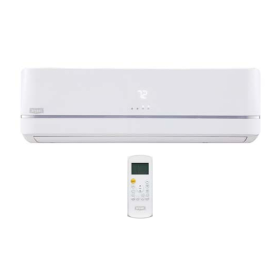
619PB
High Wall Ductless System
Sizes 09 to 36
NOTES:
Read the entire instruction manual before starting the
installation.
Images are for illustration purposes only. Actual models
may differ slightly.
Installation Instructions
TABLE OF CONTENTS
. . . . . . . . . . . . . . . . . . . . . . . . . . . . . . . . . . . . . . .
. . . . . . . . . . . . . . . . . . . . . . . . . . . . . . . . . . . . . . . . . . .
. . . . . . . . . . . . . . . . . . . . . . . . . . . . . . . . . . . . . .
. . . . . . . . . . . . . . . . . . . . . . . . . . . . . . . . . . . . .
. . . . . . . . . . . . . . . . . . . . . . . . . . . . . . .
. . . . . . . . . . . . . . . . . . . . . . . . . . . . . . .
. . . . . . . . . . . . . . . . . . . . . . . . . . . .
. . . . . . . . . . . . . . . . . . . . . . . . . . . . . . . . . . . . . . . .
. . . . . . . . . . . . . . . . . . . . . . . . . . . . . .
. . . . . . . . . . . . . . . . . . . . . . . . .
. . . . . . . . . . . . . . . . . . . . . . . . . . .
. . . . . . . . . . . . . . . . . . . . . .
. . . . . . . . . . . . . . . . . . . . . . . . .
. . . . . .
. . . . . . . . . .
PAGE
2
3
4
4
5
9
10
10
11
11
11
13
13
13
14
Advertisement
Table of Contents

Related Manuals for Bryant 619PAQ012BBMA


Summary of Contents for Bryant 619PAQ012BBMA
-
Page 1: Table Of Contents
619PB High Wall Ductless System Sizes 09 to 36 Installation Instructions TABLE OF CONTENTS PAGE SAFETY CONSIDERATIONS ......PARTS LIST . -
Page 2: Safety Considerations
SAFETY CONSIDERATIONS Installing, starting up, and servicing air−conditioning equipment WARNING can be hazardous due to system pressures, electrical components, and equipment location (roofs, elevated structures, etc.). Only trained, qualified installers and service mechanics should ELECTRICAL SHOCK HAZARD install, start−up, and service this equipment. Failure to follow this warning could result in personal Untrained personnel can perform basic maintenance functions such injury or death. -
Page 3: Parts List
- The illustration above is only a sketch. Different models may be slightly different. The following units are covered in these installation instructions. Table 2—Indoor Units Description kBTUh V-Ph-Hz ID Model No. 115-1-60 619PAQ009BBMA 115-1-60 619PAQ012BBMA 208/230-1-60 619PEQ009BBMA 208/230-1-60 619PEQ012BBMA High Wall Heat Pump 208/230-1-60 619PEQ018BBMA 208/230-1-60 619PEQ024BBMA... -
Page 4: System Requirements
SYSTEM REQUIREMENTS Allow sufficient space for airflow and unit service. See Fig. 6 for the minimum required distances between the unit and walls or ceilings. Piping IMPORTANT: Both refrigerant lines must be insulated separately. S Table 3 lists the pipe sizes for the indoor unit. Refer to the outdoor unit’s installation instructions for other allowed piping lengths and refrigerant information. -
Page 5: Dimensions
DIMENSIONS Fig. 2 - Indoor Unit Table 4—Dimensions HIGH WALL UNIT SIZE Voltage (115V) (115V) (208/230V) (208/230V) (208/230V) (208/230V) (208/230V) (208/230V) Height In (mm) 11.07 (281) 11.07 (281) 11.07 (281) 11.07 (281) 12.40 (315) 13.39 (343) 13.39 (343) 13.39 (343) Width In (mm) 33.17 (842) - Page 6 DIMENSIONS (CONT) Indoor unit outline Drain Hose Ø0.625 (16) L=21 (538) Fig. 3 - 9K and 12K...
- Page 7 DIMENSIONS (CONT) 11.32 [287] 13.29 [337] 10.39 [264] 12.58 [319] 9.57 [243] 11.73 [298] 8.78 [223] 9.54 [242] 11.32 [287] 7.25 [184] 7.53 [191] 6.21 [158] 5.98 [152] 5.08 [129] 5.08 [129] 4.13 [105] 4.13 [105] 3.15 [80] 1.08 [27] 1.08 [27] 10.21 [259] 10.66 [271]...
- Page 8 DIMENSIONS (CONT) 14.97 [380] 14.98 [380] 14.25 [362] 14.26 [362] 12.53 [318] 12.54 [319] 11.05 [281] 9.70 [246] 4.34 [110] 4.33 [110] 4.53 [115] 13.51 [343] 12.01 [305] 2.28 [58] 2.13 [54] 1.23 [31] 18.96 [482] 20.16 [512] 6.65 [169] 10.68 [271] 47.00 [1194] 10.68 [271]...
-
Page 9: Clearances
CLEARANCES CEILING 6" (0.15m) min. 5" 5" (0.13m) (0.13m) min. min. (1.8m) FLOOR Fig. 6 - Clearances NOTE: The top clearance recommended for proper return airflow is 5.9in (15cm). Reduction of this clearance may decrease unit performance. This may be reduced to 3.2in (80mm) as long as the right and left clearances are achieved. -
Page 10: Installation Tips
INSTALLATION TIPS Ideal installation locations include: Mounting Plate Dimensions Indoor Unit Different model sizes have different mounting plates. Ensure S A location where there are no obstacles near the inlet and outlet there’s enough room to mount the indoor unit (refer to Fig. 6). The following measurements can be located on these figures: area. -
Page 11: Electrical Data
ELECTRICAL DATA Table 5—Electrical Data INDOOR FAN HIGH WALL UNIT MAX FUSE CB AMP SIZE V-Ph-Hz 0.33 0.053 115-1-60 0.33 0.053 0.33 0.053 0.33 0.053 Refer to outdoor unit installation instructions – Indoor unit powered by the outdoor unit 0.49 0.067 208/230-1-60 0.61... - Page 12 INSTALL ALL POWER, INTERCONNECTING Table 6—Flare Nut Spacing WIRING, AND PIPING TO THE INDOOR UNIT A (mm) OUTER DIAM. (mm) Max. Min. 1. Run interconnecting piping and wiring from the outdoor Ø 1/4" (6.35) 0.05 (1.3) 0.03 (0.7) unit to the indoor unit. Ø...
-
Page 13: Final Tubing Check
FINAL TUBING CHECK WIRELESS REMOTE CONTROL INSTALLATION IMPORTANT: Ensure the certain factory tubing on the indoor unit has not shifted during shipment. Ensure the tubes are not Mounting Bracket (if installed on the wall) rubbing against each other or any sheet metal. Pay close attention 1. -
Page 14: Troubleshooting
O (on − light) X(off − light) For additional diagnostic information, refer to the Service Manual E2017 Bryant Heating & Cooling Systems D 7310 W. Morris St. D Indianapolis, IN 46231 Catalog No. II619PB-02 Edition Date: 09/17 Manufacturer reserves the right to discontinue, or change at any time, specifications or designs without notice and without incurring obligations.