Advertisement
Table of Contents
- 1 Table of Contents
- 2 Safety Considerations
- 3 Parts List
- 4 System Requirements
- 5 Dimensions - - Indoor
- 6 Clearances - - Indoor
- 7 Installation Tips
- 8 Indoor Unit Installation
- 9 Electrical Data
- 10 Connection Diagrams
- 11 Install All Power, Interconnecting Wiring, and Piping to Indoor Unit
- 12 Wireless Remote Control Installation
- 13 Indoor Unit
- 14 Start- -Up
- 15 Troubleshooting
- Download this manual
619P(A,E)Q*B
HIGH WALL DUCTLESS SPLIT SYSTEM
SIZES 09 TO 36
NOTE: Read the entire instruction manual before starting the
installation.
Installation Instructions
TABLE OF CONTENTS
. . . . . . . . . . . . . . . . . . . . . . . . . . . . . . . . . . . . . . .
. . . . . . . . . . . . . . . . . . . . . . . . . . . .
. . . . . . . . . . . . . . . . . . . . . . . . . . . . . . . .
. . . . . . . . . . . . . . . . . . . . . . . . . . . . . . . .
. . . . . . . . . . . . . . . . . . . . . . . . . . . . . . . . . . . . . . . . .
. . . . . . . . . . . . . . . . . . . . . . . . . . . . . .
. . . . . . . . . . . . . . . . . . . . . . . . .
. . . . . . . . . . . . . . . . . . . . . . . . . . .
. . . . . . . . . . . . . . . . . . . . . . . . . . .
. . . . . . . . . . . . . . . . . . . . . . .
. . . . . . . . . . . . . . . . . . . . . . . . . .
. . . . . . . . . . . . . . . . . . . . . .
. . . . . . .
PAGE
2
3
4
5
5
6
6
7
7
7
8
9
10
Advertisement
Table of Contents

Related Manuals for Bryant 619PAQ009BBMA


Summary of Contents for Bryant 619PAQ009BBMA
-
Page 1: Table Of Contents
619P(A,E)Q*B HIGH WALL DUCTLESS SPLIT SYSTEM SIZES 09 TO 36 Installation Instructions TABLE OF CONTENTS PAGE SAFETY CONSIDERATIONS ......PARTS LIST . -
Page 2: Safety Considerations
SAFETY CONSIDERATIONS WARNING Installing, starting up, and servicing air- -conditioning equipment can be hazardous due to system pressures, electrical components, ELECTRICAL SHOCK HAZARD and equipment location (roofs, elevated structures, etc.). Failure to follow this warning could result in personal Only trained, qualified installers and service mechanics should injury or death. -
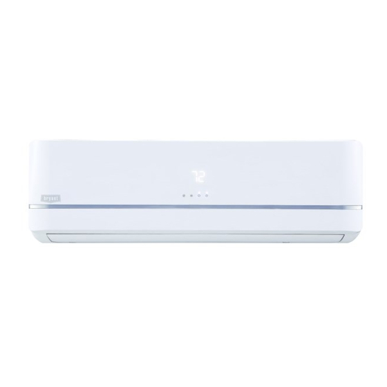
Page 3: Parts List
--- The illustration above is only a sketch. Different models may be slightly different. The following units are covered in these installation instructions. Table 1—Indoor Units Description kBTUh V ---Ph---Hz Model No 115--- 1--- 60 619PAQ009BBMA 115--- 1--- 60 619PAQ012BBMA 208/230--- 1--- 60 619PEQ009BBMA 208/230--- 1--- 60 619PEQ012BBMA High Wall... -
Page 4: System Requirements
SYSTEM REQUIREMENTS Allow sufficient space for airflow and servicing unit. See Fig. 3 for minimum required distances between unit and walls or ceilings. Piping IMPORTANT: Both refrigerant lines must be insulated separately. S Table 2 lists the pipe sizes for the indoor unit. Refer to the outdoor unit installation instructions for other allowed piping lengths and refrigerant information. -
Page 5: Dimensions - - Indoor
DIMENSIONS - - INDOOR A150772 Fig. 2 --- Indoor Unit Dimensions Table 3—Indoor Unit Dimensions HIGH WALL UNIT SIZE Voltage (115V) (115V) (208/230V) (208/230V) (208/230V) (20/230V) (208/230V) (20/230V) Height In (mm) 11.02 (280) 11.02 (280) 11.02 (280) 11.02 (280) 12.40 (315) 13.39 (343) 13.39 (343) 13.39 (343) -
Page 6: Installation Tips
INSTALLATION TIPS 2. The mounting plate should be located horizontally and level on the wall. All minimum spacings shown in Fig. 3 should Ideal installation locations include: be maintained. Indoor Unit 3. If the wall is block, brick, concrete or similar material, drill S A location where there are no obstacles near inlet and outlet area. -
Page 7: Electrical Data
ELECTRICAL DATA Table 4—Electrical Data INDOOR FAN HIGH WALL UNIT MAX FUSE CB AMP SIZE V--- Ph --- Hz 0.33 0.053 115--- 1--- 60 0.33 0.053 0.33 0.053 0.33 0.053 Refer to outdoor unit installation instructions – Indoor Unit powered from the outdoor unit 0.49 0.067 208/230--- 1--- 60... -
Page 8: Wireless Remote Control Installation
Oblique Roughness Burr A150767 Proper Do not form a rise Do not put drain end into water Fig. 13 --- Pipe Cutting A14351 c. Remove all the burrs from the cut cross section of the pipe Fig. 17 --- Proper Drain Hose Installation avoiding any burrs inside the tubes. -
Page 9: Start- -Up
START- -UP SYSTEM CHECKS Test Operation 1. Conceal the tubing where possible. Perform a test operation after completing gas leak and electrical 2. Make sure that the drain tube slopes downward along its entire length. safety check (see Fig. 19). 3. -
Page 10: Troubleshooting
Catalog No. 619PB--- 01SI E2015 Bryant Heating & Cooling Systems D 7310 W. Morris St. D Indianapolis, IN 46231 Edition Date: 12/15 Manufacturer reserves the right to discontinue, or change at any time, specifications or designs without notice and without incurring obligations.