Table of Contents
Advertisement
Quick Links
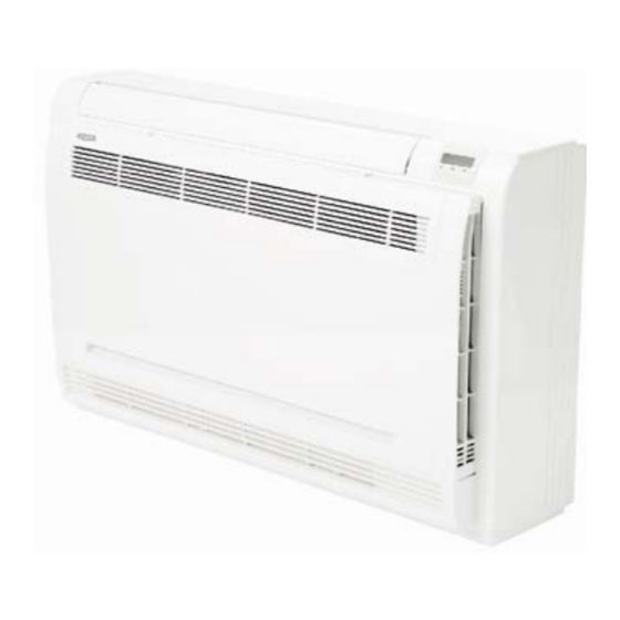
619RF
Floor Console Ductless System
Sizes 09 to 12
NOTE: Read the entire instruction manual before starting the
installation.
Installation Instructions
TABLE OF CONTENTS
. . . . . . . . . . . . . . . . . . . . . . . . . . . . . . . . . . . . . . .
. . . . . . . . . . . . . . . . . . . . . . . . . . . . . . . . . . . . . .
. . . . . . . . . . . . . . . . . . . . . . . . . . . . . . . . . . . . .
. . . . . . . . . . . . . . . . . . . . . . . . . . . . . . . .
. . . . . . . . . . . . . . . . . . . . . . . . . . . . . . . . . . . . . . . .
. . . . . . . . . . . . . . . . . . . . . . . . . . . . . .
. . . . . . . . . . . . . . . . . . . . . . . . .
. . . . . . . . . . . . . . . . . . . . . . . . . . .
. . . . . . . . . .
. . . . . . . . . . . . . . . . . . . . . . .
. . . . . . . . . . . . . . . . . . . . . . . . . .
. . . . . . .
. . . . . . . . . . .
PAGE
2
3
4
5
5
6
6
9
9
9
9
10
11
Advertisement
Table of Contents

Related Manuals for Bryant 619RF


Summary of Contents for Bryant 619RF
-
Page 1: Table Of Contents
619RF Floor Console Ductless System Sizes 09 to 12 Installation Instructions TABLE OF CONTENTS PAGE SAFETY CONSIDERATIONS ...... -
Page 2: Safety Considerations
SAFETY CONSIDERATIONS WARNING Installing, starting up, and servicing air−conditioning equipment can be hazardous due to system pressures, electrical components, ELECTRICAL SHOCK HAZARD and equipment location (roofs, elevated structures, etc.). Failure to follow this warning could result in personal Only trained, qualified installers and service mechanics should injury or death. -
Page 3: Parts List
PARTS LIST INDOOR UNIT OUTDOOR UNIT INDOOR UNIT OUTDOOR UNIT Air flow louver (at air outlet) Connecting pipe Air inlet Air inlet (with air filter inside) Air outlet Installation section Remote controller Display panel Drain pipe A150654 Fig. 1 - Parts List Note: - If the outdoor unit is higher than the indoor unit, prevent rain from flowing into the indoor unit along the connection pipe by creating a downward arc in the connection pipe before it enters the wall to the indoor unit. -
Page 4: System Requirements
SYSTEM REQUIREMENTS Allow sufficient space for airflow and servicing unit. Piping IMPORTANT: Both refrigerant lines must be insulated separately. S Minimum refrigerant line length between the indoor and outdoor units is 10 ft. (3 m). S Table 2 lists the pipe sizes for the indoor unit. Refer to the outdoor unit installation instructions for other allowed piping lengths and refrigerant information. -
Page 5: Dimensions
DIMENSIONS Fig. 2 - Indoor Unit Table 2—Dimensions Indoor UNIT SIZE Height in (mm) 8.27 (210) 8.27 (210) Width in (mm) 27.56 (700) 27.56 (700) Depth in (mm) 23.62 (600) 23.62 (600) Weight-Net Lb (kg.) 32.41 (14.7) 32.41 (14.7) -
Page 6: Clearances
CLEARANCES Fig. 3 - Indoor Unit Clearance... -
Page 7: Installation Location Requirements
INSTALLATION LOCATION DRILL A HOLE IN WALL FOR REQUIREMENTS INTERCONNECTING PIPING, DRAIN AND WIRING For maximum serviceability, it is recommended that you have A location where there are no obstacles near inlet and outlet refrigerant line flare connections and the drain connections on the area. - Page 8 3. Remove the front cover (see Fig. 9). 6. Align the center of the pipes. a. Lift the front cover’s bottom 30 degrees. b. Lift the front cover’s top. Indoor unit tubing Flare nut Pipings A150711 Fig. 12 - Align the pipe center 7.
-
Page 9: Electrical Data
CONDENSATE DRAIN CONNECTION 1.5m~2m The unit is supplied with a drain connection to connect the drain piping. When installing condensate piping, follow these recommendations: Insulating Downward declivity Condensate piping should slope downward in the direction material lower than 1/100 of the condensate flow, with a minimum gradient of 1 in. per 100 inches. -
Page 10: Wireless Remote Control Installation
WIRELESS REMOTE CONTROL START−UP INSTALLATION Test Operation Mounting Bracket (if installed on the wall) Perform a test operation after completing a gas leak and electrical safety check. 1. Use the two screws supplied with the control to attach the mounting bracket to the wall in a location selected by the 1. -
Page 11: Troubleshooting
TROUBLESHOOTING For ease of service, the systems are equipped with diagnostic code If possible, always check the diagnostic codes displayed on the display LEDs on both the indoor and outdoor units. indoor unit first. The indoor diagnostic display is a combination of flashing LEDs The diagnostic codes displayed in the indoor and outdoor units are on the display panel or the front of the unit. - Page 12 E2016 Bryant Heating & Cooling Systems 7310 W. Morris St. Indianapolis, IN 46231 Edition Date: 03/16 Catalog No. 619RF-02SI Manufacturer reserves the right to discontinue, or change at any time, specifications or designs without notice and without incurring obligations. Replaces: 619RF-01SI...