Advertisement
Quick Links
REPAIR
KEEP FOR REFERENCE.
Read this and all related manuals for
important warnings and instructions.
INSTRUCTIONS
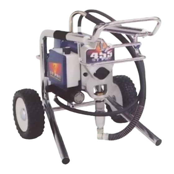
395/455/495st Pro
Airless Paint Sprayers
3000 psi (210 bar, 21 MPa ) Maximum Working Pressure
220-240 VAC
Type
Series Stand
395st Prot A
232926
233034
495st Prot A
232946 232947
100-120 VAC
Type
Series Stand
395st Prot A
232923
233033
495st Prot A
232943 232944
120 VAC
Type
Series Stand
395st Prot A
232920
455st Prot A
495st Prot A
232940 232941
Related manuals
Component Function and Identification
Grounding
. . . . . . . . . . . . . . . . . . . . . . . . . . . . . . . . . . . . .
Troubleshooting
. . . . . . . . . . . . . . . . . . . . . . . . . . . . . . . .
General Repair Information
Spin Test
. . . . . . . . . . . . . . . . . . . . . . . . . . . . . . . . . . . . .
Motor Brush Replacement
On/Off Switch Replacement
GRACO INC. P.O. BOX 1441 MINNEAPOLIS, MN 55440-1441
Lo-boy Hi-boy
232948
Lo-boy Hi-boy
232945
Lo-boy Hi-boy
232931
232932
232942
Table of Contents
. . . . . . . . . . . .
3
5
5
. . . . . . . . . . . . . . . . . . . . . .
4
10
. . . . . . . . . . . . . . . . . . . . .
10
. . . . . . . . . . . . . . . . . . . .
12
ECOPYRIGHT 1999, GRACO INC.
Graco Inc. is registered to I.S. EN ISO 9001
First choice when
quality counts.t
. . . . . . .
309070
. . . . . . .
309052
. . . . . . .
309054
. . . . . . . . . . . . . . . . . . . . .
309057
. . . . . . .
309058
. . . . . . . . . . . . . . . . . . . . . . . . . . . .
. . . . . . . . . . . . . . . . . . . . . . . . . . . . . . . .
. . . . . . . . . . . . . . . . . . . . . . . . . .
. . . . . . . . . . . . . . . . . . . . . . . . . . . . . . .
309056
Rev. A
9546A
232920
. . . . . . .
309053
. . . . . . .
309055
. . . . . . . . . . . . . . . . . . . . . . .
. . . . . . . . . . . . . . . . . . . .
. . . . . . . . . . . . . . .
15
17
18
19
20
20
20
Advertisement

Related Manuals for Graco 395st Pro


Summary of Contents for Graco 395st Pro
-
Page 1: Table Of Contents
....... GRACO INC. P.O. BOX 1441 MINNEAPOLIS, MN 55440–1441 ECOPYRIGHT 1999, GRACO INC. Graco Inc. is registered to I.S. EN ISO 9001... - Page 2 WARNING ADVERTÊNCIA Poderá ocorrer incêndio e explosão quando for pulverizado ou injetado Fire and explosion hazard: Solvent and paint fumes can ignite or líquido inflamável numa área onde houver má circulação de ar; vapores explode. inflamáveis poderão incendiar-se a partir de uma chama ou fagulhas a To help prevent a fire and explosion: descoberto.
- Page 3 Component Identification and Function 8050A Fig. 1 Motor DC motor, permanent magnet, totally enclosed, fan cooled Drive Assembly Transfers power from DC motor to displacement pump Displacement Pump Transfers fluid to be sprayed from source through spray gun Fluid Outlet Spray gun is connected here Prime Valve Used to prime and drain sprayer (also relieves fluid outlet pressure) when...
- Page 4 General Repair Information Pressure Relief Procedure 1. Keep all screws, nuts, washers, gaskets, and electrical fittings removed during repair proce- dures. These parts are not normally provided with WARNING replacement assemblies. INJECTION HAZARD WARNING System pressure must be manually relieved to prevent system from starting ELECTRIC SHOCK HAZARD or spraying accidentally.
- Page 5 Grounding WARNING Grounded Grounding Plug Outlets Improper installation or alteration of grounding plug results in risk of electric shock, fire or explosion that could cause serious injury or death. 1. 220–240 Vac models require a 50 Hz, 10A circuit with a grounding receptacle. 100–120 Vac models 240 Vac model shown require a 50/60 Hz, 15A circuit with a grounding Fig.
- Page 6 Troubleshooting MOTOR WON’T OPERATE (Continued) WHAT TO CHECK WHAT TO DO TYPE OF PROBLEM If check is OK, go to next check When check is not OK refer to this column Basic Electrical Problems 1. That motor leads are securely fastened and 1.
- Page 7 Troubleshooting LOW OR FLUCTUATING OUTPUT WHAT TO CHECK WHAT TO DO TYPE OF PROBLEM If check is OK, go to next check When check is not OK refer to this column Low Output 1. For worn spray tip. 1. Follow Pressure Relief Procedure Warn- ing, then replace tip.
- Page 8 Troubleshooting LOW OR FLUCTUATING OUTPUT WHAT TO CHECK WHAT TO DO TYPE OF PROBLEM If check is OK, go to next check When check is not OK refer to this column Motor runs and pump strokes 1. Paint supply. 1. Refill and reprime pump. 2.
- Page 9 Troubleshooting MOTOR IS HOT AND RUNS INTERMITTENTLY WHAT TO CHECK WHAT TO DO TYPE OF PROBLEM If check is OK, go to next check When check is not OK refer to this column Motor is hot and runs intermit- 1. Determine if sprayer was operated at high 1.
- Page 10 Spin Test Setup Armature, Brushes, and Motor Wiring Open Circuit Test (Continuity) 1. Connect red and black motor leads together with Electric Shock Hazard; page 4. test lead. Turn motor fan by hand at about two revolutions per second. To check armature, motor winding and brush electrical 2.
- Page 11 Motor Brush Replacement 4. Fig. 5. Push in spring clip (A) to release hook (B) from brush holder (C). Pull out spring clip (A). 5. Fig. 5. Pull brush lead (D) out of terminal (E). Remove brush (F). Motor lead; do not disconnect Minimum 0.5”...
- Page 12 On/Off Switch Replacement 120 Vac (232920, 232931, 232932, 232940 – 232942) Removal Installation 1. Install new ON/OFF switch (23). Install locking ring Relieve pressure; page 4. (24) and toggle boot (25). 2. Fig. 7. Remove four screws (18) and pressure control cover (39).
- Page 13 On/Off Switch Replacement 100 Vac (232923, 232943 – 232945, 233033) Removal Installation 1. Install new ON/OFF switch (23). Install locking ring Relieve pressure; page 4. (24) and toggle boot (25). 2. Fig. 8. Remove four screws (18) and pressure 2. Connect four wires (A) to ON/OFF switch (23). control cover (39).
- Page 14 On/Off Switch Replacement 240 Vac (232926, 232946 – 232948, 233034) Removal Installation 1. Install new ON/OFF switch (23). Install locking ring Relieve pressure; page 4. (24) and toggle boot (25). 2. Fig. 9. Remove pressure control cover (39). 2. Connect four wires (A) to ON/OFF switch. 3.
-
Page 15: Pressure Control Repair
Pressure Control Repair Motor Control Board Removal Installation 1. Clean pad on rear of motor control board. Apply Refer to Fig. 7, 8 or 9 depending on sprayer voltage. small amount of thermal compound 073019 to pad. 2. Fig. 7. Install motor control board (35) with five screws (36). - Page 16 Pressure Control Repair Digital Display Messages No display does not mean that sprayer is not pressurized. Relieve pressure before repair; page 4. DISPLAY SPRAYER INDICATION ACTION OPERATION No Display Sprayer stops. Power is not applied. Loss of power Check power source. Relieve pressure before repair or dis- Sprayer may be pressurized.
-
Page 17: Drive Housing Replacement
Drive Housing Replacement 5. Remove two back screws (22). CAUTION 6. Pull drive housing (10) off of motor (1). Do not drop gear cluster (7) when removing drive housing (10). Gear cluster may stay engaged in Assembly motor front end bell or drive housing. 1. -
Page 18: Motor Replacement
Motor Replacement Disassembly 6. Remove strain relief (37, page 12, 13, 14). 7. Remove three screws (22) behind board and remove control housing (21). Relieve pressure; page 4. 8. Remove four screws (22) and motor (1) from frame (63). 2. Remove pump (13); Displacement Pump Re- Assembly placement, page 19. -
Page 19: Displacement Pump Replacement
1. Fig. 14. Extend pump piston rod fully. Apply grease to top of pump rod at (A) or inside connecting rod. 9576A Fig. 15 7. Fig. 16. Fill packing nut with Graco TSL until fluid flows onto top of seal. 9575A Fig. 14 9577A Fig. -
Page 20: Technical Data
1–800–690–2894 to identify the nearest distributor. All written and visual data contained in this document reflects the latest product information available at the time of publication. Graco reserves the right to make changes at any time without notice. Sales Offices: Minneapolis, Detroit Foreign Offices: Belgium, Korea, Hong Kong, Japan www.graco.com...