Table of Contents
Advertisement
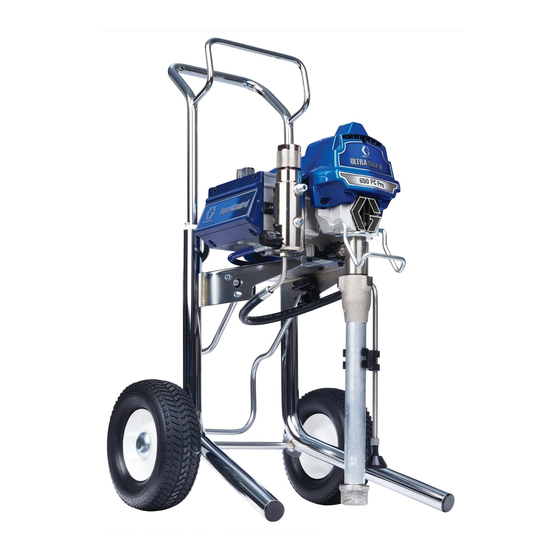
Operation, Parts
Electric Airless
Sprayers
For portable airless spraying of architectural paints and coatings. For
professional use only. Not approved for use in explosive atmospheres or
hazardous locations.
490/495/595/650/395EU Models:
3300 psi (228 bar, 22.8 MPa) Maximum Working Pressure
See page 3 for additional model information.
Important Safety Instructions
Read all warnings and instructions in this manual, in related manuals, and on the unit
before using the equipment. Be familiar with the controls and the proper usage of the
equipment. Save these instructions.
Gun – 3A6285 (Contractor PC)
Use only genuine Graco replacement parts.
The use of non-Graco replacement parts may void warranty.
Related Manuals
Pump – 334599
3A6491E
EN
Advertisement
Table of Contents

Related Manuals for Graco Ultra MAX II 490 PC Pro


Summary of Contents for Graco Ultra MAX II 490 PC Pro
-
Page 1: Important Safety Instructions
Be familiar with the controls and the proper usage of the equipment. Save these instructions. Related Manuals Gun – 3A6285 (Contractor PC) Pump – 334599 Use only genuine Graco replacement parts. The use of non-Graco replacement parts may void warranty. -
Page 2: Table Of Contents
Graco Standard Warranty ........ -
Page 3: Models
Models Models Hi-Boy Stand Lo-Boy Model Ultra MAX II 17E852 17E853 17E854 490 PC Pro Ultimate MX II 826243 826244 826245 490 PC Pro Ultra MAX II 17E855 17E856 17E857 495 PC Pro 110474 Ultimate MX II 826246 826247 826248 Certified to 495 PC Pro CAN/CSA... -
Page 4: Warnings
Warnings Warnings The following warnings are for the setup, use, grounding, maintenance, and repair of this equipment. The exclamation point symbol alerts you to a general warning and the hazard symbols refer to procedure-specific risks. When these symbols appear in the body of this manual or on warning labels, refer back to these Warnings. -
Page 5: Fire And Explosion Hazard
All parts of the spray system, including the pump, hose assembly, spray gun, and objects in and around the spray area shall be properly grounded to protect against static discharge and sparks. Use Graco conductive or grounded high-pressure airless paint sprayer hoses. - Page 6 • Check hoses and parts for signs of damage. Replace any damaged hoses or parts. • This system is capable of producing 3300 psi. Use Graco replacement parts or accessories that are rated a minimum of 3300 psi. • Always engage the trigger lock when not spraying. Verify the trigger lock is functioning properly.
- Page 7 Warnings ELECTRIC SHOCK HAZARD This equipment must be grounded. Improper grounding, setup, or usage of the system can cause electric shock. • Turn off and disconnect power cord before servicing equipment. • Connect only to grounded electrical outlets. • Use only 3-wire extension cords. •...
-
Page 8: Component Identification
Component Identification Component Identification Stand Models Suction Tube ON/OFF Switch Pump Pressure Control Fluid Outlet Prime Valve Power Cord Wrap Tip Guard Filter Spray Tip Finger Guard / TSL Fill Point W BlueLink™ Status Light (if applicable) Airless Hose Model/Serial Tag (Not shown, located Power Cord on bottom of unit.) Trigger Lock... -
Page 9: Lo-Boy Models
Component Identification Lo-Boy Models M Drain Tube ON/OFF Switch Suction Tube Pressure Control Pump Prime Valve Fluid Outlet Tip Guard Filter Spray Tip Finger Guard / TSL Fill Point W BlueLink Status Light (if applicable) Airless Hose Model/Serial Tag (Not shown, located Power Cord on bottom of unit.) Trigger Lock... -
Page 10: Hi-Boy Models
Component Identification Hi-Boy Models Pump ON/OFF Switch Fluid Outlet Pressure Control Hanger Prime Valve Filter Tip Guard Finger Guard / TSL Fill Point Spray Tip Pail Hook W BlueLink Status Light (if applicable) Airless Hose Model/Serial Tag (Not shown, located Power Cord on bottom of unit.) Trigger Lock... -
Page 11: Grounding
Grounding Grounding Do not place pail on a non-conductive surface such as paper or cardboard which interrupts grounding continuity. The equipment must be grounded to reduce the risk of static sparking and electric shock. An electric or static spark can cause fumes to ignite or explode. An improper ground can cause electric shock. -
Page 12: Pressure Relief Procedure
Pressure Relief Procedure Pressure Relief Procedure Follow the Pressure Relief Turn pressure control to the lowest Procedure whenever you see this setting. symbol. This equipment stays pressurized until pressure is manually relieved. To help prevent serious injury from pressurized Put drain tube in a pail and turn prime fluid, such as skin injection, splashed fluid valve down to relieve pressure. -
Page 13: Setup
When first setup is performed remove shipping plug from fluid outlet. Trigger Lock Connect Graco airless hose to fluid outlet. Use wrenches to tighten securely. Always engage the trigger lock when sprayer is stopped to prevent the gun from being triggered accidentally by hand or if dropped or bumped. - Page 14 Setup Engage trigger lock. Fill throat packing nut with TSL to prevent premature packing wear. Do this daily or each time you spray. Place the TSL bottle nozzle into the top center opening in the grill at the front of the sprayer. Squeeze bottle to dispense enough TSL to fill the space between the pump rod and packing nut seal.
- Page 15 Setup ti24640a ti24651a 12. Turn pressure control to OFF. 10. Turn prime valve down. 13. Turn ON/OFF switch to ON position. 14. Turn prime valve horizontal. Disengage trigger lock. 15. Turn pressure control to Prime/Slow. 16. Hold a metal part of the gun firmly to a grounded metal pail.
-
Page 16: Startup
Startup Startup Turn pressure control to Fast Flush to start motor. Allow paint to circulate through drain tube for 15 seconds. Perform Pressure Relief Procedure, page 12. Turn prime valve horizontal. Disengage Turn pressure control to lowest trigger lock. pressure. Turn ON/OFF switch to ON position. - Page 17 Startup Move gun to paint pail and trigger for 20 seconds. Release trigger and allow sprayer to build pressure. Engage trigger lock. High-pressure spray is able to inject toxins into the body and cause serious bodily injury. Do not stop leaks with hand or rag. Inspect for leaks.
-
Page 18: Operation
Operation Operation Spray Tip Installation 4. Screw assembly onto gun. Tighten. To avoid serious injury from skin injection do not put your hand in front of the spray tip when installing or removing the spray tip and tip guard. 1. Perform Pressure Relief Procedure, page 12. -
Page 19: Clear Spray Tip Clog
Operation Clear Spray Tip Clog Spray test pattern. Adjust pressure to eliminate heavy edges. To avoid injury, never point gun at your hand or into a rag! Release trigger. Engage trigger lock. Rotate Spray Tip. Disengage trigger lock. Trigger gun at waste area to clear clog. -
Page 20: Cleanup
Operation Cleanup Place fluid intake in flushing fluid. Use water for water base paint and mineral spirits for oil-based paint. Place drain tube in waste pail. Perform Pressure Relief Procedure, page 12. Remove tip guard and Spray Tip. For additional information, see separate gun manual. - Page 21 Operation Fast Flush Hose and Gun 10. Raise fluid intake above flushing fluid. To flush airless hose and spray gun, turn prime valve horizontal. Hold gun against waste pail. Disengage trigger lock. Trigger gun and turn pressure control to Fast Flush operate until the pump runs steady and flushing fluid appears.
- Page 22 Operation 13. Turn pressure control knob to OFF and 15. If flushing with water, flush again with turn ON/OFF switch to OFF position. mineral spirits or Pump Armor to leave a Disconnect power to sprayer. protective coating to prevent freezing or corrosion.
-
Page 23: Digital Display
Operation Digital Display Pressure display appears. Dashes appear when pressure is less than 200 psi (14 bar, 1.4 MPa). Most models are equipped with a digital display. This section explains how to use this feature. ti2786a Short press display button to move to Job Gallons (or Liters x 10). - Page 24 Operation Stored Data Display Short press display button and the last error code is displayed: e.g., E=07. See Perform Pressure Relief Procedure, Electrical, page 30 for trouble shooting page 12. information. Press display button and turn ON/OFF switch to ON position. ti7490b Press and hold display button to clear error code to zero.
-
Page 25: Bluelink™ App
BlueLink™ App BlueLink™ App Enabling or Disabling (If applicable) Download the Graco BlueLink app from the BlueLink Apple App Store or Google Play to connect ® to the paint sprayer via Bluetooth The BlueLink app allows you to access sprayer information, settings, statistics, and... -
Page 26: Maintenance
Packing nut can be tightened without 0-ring removal. Maintenance can be scheduled and tracked via the Graco BlueLink app. Recycling and Disposal at End of Life Dismantle and recycle: At the end of the product’s useful life, dismantle and recycle it in a responsible •... -
Page 27: Troubleshooting
Troubleshooting Troubleshooting Mechanical/Fluid Flow Follow Pressure Relief Procedure, Check all possible problems and causes page 12, before checking or repairing. before disassembling the unit. What to Check What to Do If check is OK, go to next When check is not OK, Problem check refer to this column... - Page 28 Troubleshooting What to Check What to Do If check is OK, go to next When check is not OK, Problem check refer to this column Pump output is low Pump rod damage. Repair pump. See pump manual. Low stall pressure. Turn pressure knob fully clockwise.
- Page 29 Troubleshooting What to Check What to Do If check is OK, go to next When check is not OK, Problem check refer to this column Pump is difficult to prime Air in pump or hose. Check and tighten all fluid connections.
-
Page 30: Electrical
1/2 turn. Error Code Messages CODE MESSAGE ACTION HIGH PRESSURE Check for clogs. Use only Graco spray hoses, DETECTED - RELIEVE use a minimum of 50ft/15m. PRESSURE PRESSURE TRANSDUCER Check transducer connection. NOT DETECTED... - Page 31 Troubleshooting Problem What to Check How to check Sprayer does not run at all See flow chart, page 35. Control board status light never lights Sprayer does not shut off Control board. Replace control board. Control board status light blinks 2 times repeatedly Check transducer or transducer Sprayer does not run at all...
- Page 32 Troubleshooting Problem What to Check How to check Sprayer does not run at all Check transducer or transducer Turn ON/OFF switch OFF and connections (control board is not disconnect power to sprayer. detecting a pressure signal). Check transducer and connections to Control board status light blinks 3 control board.
- Page 33 Troubleshooting Problem What to Check How to check 5.Perform Spin Test: Test at large 4-pin motor field connector. Disconnect fluid pump from sprayer. Test motor by placing a jumper across pins 1 & 2. Rotate motor fan at about 2 revolutions per second.
- Page 34 Troubleshooting Problem What to Check How to check Sprayer does not run at all Motor is hot or there is a fault in the Allow sprayer to cool. If sprayer runs motor thermal device. when cool, correct cause of overheating. Keep sprayer in cooler Control board status light blinks 6 location with good ventilation.
- Page 35 Troubleshooting Electrical cont... Sprayer Will Not Run (See following page for steps) 3A6491E...
- Page 36 Troubleshooting 3A6491E...
- Page 37 Troubleshooting Electrical cont... Sprayer Will Not Shut Off Perform Pressure Relief Procedure, Remove control box cover so the page 12. Leave prime valve open control board status light can be viewed (down) and turn ON/OFF switch OFF. if available. Troubleshooting Procedure Plumb pressure gauge into paint hose, Mechanical problem: plug sprayer in, and turn power switch ON.
-
Page 38: 490/495/395Eu Stand Sprayers
490/495/395EU Stand Sprayers 490/495/395EU Stand Sprayers Ref. Torque 140-160 in-lb (15.8 - 18.1 N•m) 23-27 in-lb (2.6 - 3.0 N•m) Hammer Tight 20-30 ft-lb (33.9 - 40.7 N•m) page 50. 3A6491E... - Page 39 490/495/395EU Stand Sprayers 490/495/395EU Stand Sprayers Parts List Ref. Part Description Qty. Ref. Part Description Qty. 246381 HOSE, drain, stand, 107434 BEARING, thrust includes 39, 62 116073 WASHER, thrust 276897 STRAINER, 7/8-14 unf 116074 WASHER, thrust 19Y413 KIT, frame, standmount, 116079 BEARING, thrust Includes 67...
-
Page 40: 490/495/595 Lo-Boy Sprayers
490/495/595 Lo-Boy Sprayers 490/495/595 Lo-Boy Sprayers Ref. Torque 140-160 in-lb (15.8 - 18.1 N•m) 23-27 in-lb (2.6 - 3.0 N•m) Hammer Tight 20-30 ft-lb (33.9 - 40.7 N•m) See page 50. 3A6491E... - Page 41 490/495/595 Lo-Boy Sprayers 490/495/595 Lo-Boy Sprayers Parts List Ref. Part Description Qty. Ref. Part Description Qty. 287807 Model 595 107434 BEARING, thrust 246381 HOSE, drain, stand, 116073 WASHER, thrust includes 39, 62 116074 WASHER, thrust 276897 STRAINER, 7/8-14 unf 116079 BEARING, thrust 246250 FRAME, cart, lo...
-
Page 42: 650 Lo-Boy Sprayer
650 Lo-Boy Sprayer 650 Lo-Boy Sprayer Ref. Torque 140-160 in-lb (15.8 - 18.1 N•m) 30-35 in-lb (3.4 - 4.0 N•m) Hammer Tight 20-30 ft-lb (33.9 - 40.7 N•m) See page 50. 3A6491E... - Page 43 650 Lo-Boy Sprayer 650 Lo-Boy Sprayers Parts List Ref. Part Description Qty. Ref. Part Description Qty. 24Y424 FRAME, cart, lo 107434 BEARING, thrust 248216 KIT, hose suction 116073 WASHER, thrust See page GUN, spray (not shown) 116074 WASHER, thrust 116079 BEARING, thrust 15D000 CLIP, drain line...
-
Page 44: 490/495/595/395Eu Hi-Boy Sprayers
490/495/595/395EU Hi-Boy Sprayers 490/495/595/395EU Hi-Boy Sprayers Ref. Torque 140-160 in-lb (15.8 - 18.1 N•m) 30-35 in-lb (3.4 - 4.0 N•m) 23-27 in-lb (2.6 - 3.0 N•m) Hammer tight 25-30 ft-lb (33.9 - 40.7 N•m) See page 50. 3A6491E... - Page 45 490/495/595/395EU Hi-Boy Sprayers 490/495/595/395EU Hi-Boy Sprayers Parts List Part Description Ref. Qty. Part Description Ref. Qty. See page GUN, spray (not shown) 107434 BEARING, thrust 116073 WASHER, thrust 276888 CLIP, drain line 116074 WASHER, thrust See page LABEL, warning 116079 BEARING, thrust 117501...
-
Page 46: 650 Hi-Boy Sprayer
650 Hi-Boy Sprayer 650 Hi-Boy Sprayer Ref. Torque 140-160 in-lb (15.8 - 18.1 N•m) 30-35 in-lb (3.4 - 4.0 N•m) 23-27 in-lb (2.6 - 3.0 N•m) Hammer tight 25-30 ft-lb (33.9 - 40.7 N•m) See page 50. 3A6491E... - Page 47 650 Hi-Boy Sprayer 650 Hi-Boy Sprayers Parts List Part Description Ref. Qty. Part Description Ref. Qty. 17C485 FRAME, cart, hi 107434 BEARING, thrust 19Y309 KIT, stinger tube, includes 116073 WASHER, thrust 116074 WASHER, thrust See page GUN, spray (not shown) 116079 BEARING, thrust 117501...
-
Page 48: Accessories And Labels
Accessories and Labels Accessories and Labels Ref. 52 Ref. 34 Label, Card, Ref. 46 Front, Ref. 53 Ref. 61 Ref. 63 Ref. 65 Sprayer Medical Hose, 1/4 Upper/ Label, Gun, Label, Label, Model Alert in. x 50 ft Lower Side Spray Warning Warning... - Page 49 Notes Notes 3A6491E...
-
Page 50: Control Box
Control Box Control Box Ref. Torque 140-160 in-lb (15.8 - 18.1 N•m) 20-25 in-lb (2.3 - 2.8 N•m) 37-43 ft-lb (50.2 - 58.3 N•m) 130-150 in-lb (14.7 - 16.9 N•m) 3A6491E... - Page 51 Control Box Control Box Parts List Ref. Part Description Qty. Ref. Part Description Qty. 19Y382 230V, 650 models 117828 PACKING, o-ring 19Y383 110V, 650 models 111457 PACKING, o-ring 17P731 LABEL, pressure, 111600 PIN, grooved adjustment, w/FastFlush 277364 GASKET, seat, valve COVER, control 120405 SCREW, mach, Phillips,...
-
Page 52: Battery Replacement
Battery Replacement Battery Replacement (BlueLink Units Only) 3A6491E... -
Page 53: Wiring Diagrams
Wiring Diagrams Wiring Diagrams 110/120V Models 395EU, 490, 495, 595 3A6491E... - Page 54 Wiring Diagrams 230V Models 490, 495, 595 NOTICE Heat from inductor coil of filter board may destroy wire insulation that comes in contact with it. Exposed wires could cause shorts and component damage. Bundle and tie loose wires so none lay in contact with inductor coil on the filter board.
- Page 55 Wiring Diagrams 120V/110V Model 650 3A6491E...
- Page 56 Wiring Diagrams 230V Model 650 NOTICE Heat from inductor coil of filter board may destroy wire insulation that comes in contact with it. Exposed wires could cause shorts and component damage. Bundle and tie loose wires so none lay in contact with inductor coil on the filter board.
- Page 57 Notes Notes 3A6491E...
-
Page 58: Technical Specifications
Technical Specifications Technical Specifications 490/495/595/650/395EU Metric Sprayer Maximum fluid working pressure 3300 psi 228 bar, 22.8 MPa Maximum Delivery 395EU/490 0.54 gpm 2.0 lpm 0.60 gpm 2.3 lpm 0.70 gpm 2.6 lpm 0.80 gpm 3.0 lpm Maximum Tip Size 395EU/490 0.023 0.023 0.025... - Page 59 Technical Specifications 490/495/595/650/395EU Metric Width Stand 14 in. 35.6 cm Lo-Boy (490/495/395EU/595) 20 in. 50.6 cm Lo-Boy (650) 22.5 in. 57 cm Hi-Boy 20.5 in. 52.1 cm Weight Stand 395EU 45.1 lb. 20.5 kg 490 / 495 34 lb. 15 kg Lo-Boy 395EU 63 lb.
-
Page 60: Compliance
Compliance Compliance Radio Frequency Approvals Transmitter Frequency (all models): 2.4GHz NOTE: FCC/IC Notice (all models) Transmitter Power (all models): +8dBm Contains FCC ID: QOQBGM13P Contains IC: 5123A-BGM13P The enclosed device complies with Part 15 of the FCC Rules and with Industry Canada license-exempt RSS standard(s). -
Page 61: Graco Standard Warranty
Graco’s written recommendations. This warranty does not cover, and Graco shall not be liable for general wear and tear, or any malfunction, damage or wear caused by faulty installation, misapplication, abrasion, corrosion, inadequate or improper maintenance, negligence, accident, tampering, or substitution of non-Graco component parts. -
Page 62: Graco Information
Graco Information Graco Information For the latest information about Graco products, visit www.graco.com. For patent information, see www.graco.com/patents. TO PLACE AN ORDER, contact your Graco distributor or call 1-800-690-2894 to identify the nearest distributor. 3A6491E... - Page 63 Graco Information 3A6491E...
- Page 64 Original instructions. This manual contains English. MM 3A6491 Graco Headquarters: Minneapolis International Offices: Belgium, China, Japan, Korea GRACO INC. AND SUBSIDIARIES • P.O. BOX 1441 • MINNEAPOLIS MN 55440-1441 • USA Copyright 2018, Graco Inc. All Graco manufacturing locations are registered to ISO 9001. www.graco.com...